EP1137028A2 - Feuille avec disques élastiques et dispositif de commutation utilisant cette feuille - Google Patents
Feuille avec disques élastiques et dispositif de commutation utilisant cette feuille Download PDFInfo
- Publication number
- EP1137028A2 EP1137028A2 EP01302120A EP01302120A EP1137028A2 EP 1137028 A2 EP1137028 A2 EP 1137028A2 EP 01302120 A EP01302120 A EP 01302120A EP 01302120 A EP01302120 A EP 01302120A EP 1137028 A2 EP1137028 A2 EP 1137028A2
- Authority
- EP
- European Patent Office
- Prior art keywords
- adhesive
- sheet
- plate springs
- portions
- projected
- Prior art date
- Legal status (The legal status is an assumption and is not a legal conclusion. Google has not performed a legal analysis and makes no representation as to the accuracy of the status listed.)
- Granted
Links
- 239000000853 adhesive Substances 0.000 claims abstract description 205
- 230000001070 adhesive effect Effects 0.000 claims abstract description 205
- 239000000758 substrate Substances 0.000 claims description 28
- 239000000428 dust Substances 0.000 abstract description 11
- 230000003068 static effect Effects 0.000 abstract description 4
- 230000015572 biosynthetic process Effects 0.000 description 5
- 230000000881 depressing effect Effects 0.000 description 5
- 239000012790 adhesive layer Substances 0.000 description 4
- 238000010276 construction Methods 0.000 description 4
- 238000010586 diagram Methods 0.000 description 4
- 238000004519 manufacturing process Methods 0.000 description 4
- RYGMFSIKBFXOCR-UHFFFAOYSA-N Copper Chemical compound [Cu] RYGMFSIKBFXOCR-UHFFFAOYSA-N 0.000 description 3
- 239000011889 copper foil Substances 0.000 description 3
- 230000005611 electricity Effects 0.000 description 3
- 238000005530 etching Methods 0.000 description 3
- 229920006267 polyester film Polymers 0.000 description 3
- 238000007639 printing Methods 0.000 description 3
- 239000002390 adhesive tape Substances 0.000 description 2
- 238000004891 communication Methods 0.000 description 2
- 230000002093 peripheral effect Effects 0.000 description 2
- 229920001721 polyimide Polymers 0.000 description 2
- 229910000906 Bronze Inorganic materials 0.000 description 1
- 239000004593 Epoxy Substances 0.000 description 1
- OAICVXFJPJFONN-UHFFFAOYSA-N Phosphorus Chemical compound [P] OAICVXFJPJFONN-UHFFFAOYSA-N 0.000 description 1
- BQCADISMDOOEFD-UHFFFAOYSA-N Silver Chemical compound [Ag] BQCADISMDOOEFD-UHFFFAOYSA-N 0.000 description 1
- 239000003522 acrylic cement Substances 0.000 description 1
- 239000002313 adhesive film Substances 0.000 description 1
- 239000010974 bronze Substances 0.000 description 1
- 239000003795 chemical substances by application Substances 0.000 description 1
- 230000001595 contractor effect Effects 0.000 description 1
- KUNSUQLRTQLHQQ-UHFFFAOYSA-N copper tin Chemical compound [Cu].[Sn] KUNSUQLRTQLHQQ-UHFFFAOYSA-N 0.000 description 1
- 238000006073 displacement reaction Methods 0.000 description 1
- 238000005286 illumination Methods 0.000 description 1
- 238000003780 insertion Methods 0.000 description 1
- 230000037431 insertion Effects 0.000 description 1
- 238000007689 inspection Methods 0.000 description 1
- 238000012986 modification Methods 0.000 description 1
- 230000004048 modification Effects 0.000 description 1
- 239000000049 pigment Substances 0.000 description 1
- 229920001225 polyester resin Polymers 0.000 description 1
- 239000004645 polyester resin Substances 0.000 description 1
- 238000004080 punching Methods 0.000 description 1
- 238000007650 screen-printing Methods 0.000 description 1
- 229910052709 silver Inorganic materials 0.000 description 1
- 239000004332 silver Substances 0.000 description 1
- 238000005476 soldering Methods 0.000 description 1
- 229910001220 stainless steel Inorganic materials 0.000 description 1
- 239000010935 stainless steel Substances 0.000 description 1
Images


Classifications
-
- H—ELECTRICITY
- H01—ELECTRIC ELEMENTS
- H01H—ELECTRIC SWITCHES; RELAYS; SELECTORS; EMERGENCY PROTECTIVE DEVICES
- H01H13/00—Switches having rectilinearly-movable operating part or parts adapted for pushing or pulling in one direction only, e.g. push-button switch
- H01H13/70—Switches having rectilinearly-movable operating part or parts adapted for pushing or pulling in one direction only, e.g. push-button switch having a plurality of operating members associated with different sets of contacts, e.g. keyboard
-
- H—ELECTRICITY
- H01—ELECTRIC ELEMENTS
- H01H—ELECTRIC SWITCHES; RELAYS; SELECTORS; EMERGENCY PROTECTIVE DEVICES
- H01H13/00—Switches having rectilinearly-movable operating part or parts adapted for pushing or pulling in one direction only, e.g. push-button switch
- H01H13/70—Switches having rectilinearly-movable operating part or parts adapted for pushing or pulling in one direction only, e.g. push-button switch having a plurality of operating members associated with different sets of contacts, e.g. keyboard
- H01H13/702—Switches having rectilinearly-movable operating part or parts adapted for pushing or pulling in one direction only, e.g. push-button switch having a plurality of operating members associated with different sets of contacts, e.g. keyboard with contacts carried by or formed from layers in a multilayer structure, e.g. membrane switches
-
- H—ELECTRICITY
- H01—ELECTRIC ELEMENTS
- H01H—ELECTRIC SWITCHES; RELAYS; SELECTORS; EMERGENCY PROTECTIVE DEVICES
- H01H2205/00—Movable contacts
- H01H2205/016—Separate bridge contact
-
- H—ELECTRICITY
- H01—ELECTRIC ELEMENTS
- H01H—ELECTRIC SWITCHES; RELAYS; SELECTORS; EMERGENCY PROTECTIVE DEVICES
- H01H2205/00—Movable contacts
- H01H2205/016—Separate bridge contact
- H01H2205/018—Support points upwardly concave
-
- H—ELECTRICITY
- H01—ELECTRIC ELEMENTS
- H01H—ELECTRIC SWITCHES; RELAYS; SELECTORS; EMERGENCY PROTECTIVE DEVICES
- H01H2205/00—Movable contacts
- H01H2205/016—Separate bridge contact
- H01H2205/024—Means to facilitate positioning
- H01H2205/026—Adhesive sheet
-
- H—ELECTRICITY
- H01—ELECTRIC ELEMENTS
- H01H—ELECTRIC SWITCHES; RELAYS; SELECTORS; EMERGENCY PROTECTIVE DEVICES
- H01H2209/00—Layers
- H01H2209/024—Properties of the substrate
- H01H2209/03—Properties of the substrate elastomeric
-
- H—ELECTRICITY
- H01—ELECTRIC ELEMENTS
- H01H—ELECTRIC SWITCHES; RELAYS; SELECTORS; EMERGENCY PROTECTIVE DEVICES
- H01H2209/00—Layers
- H01H2209/024—Properties of the substrate
- H01H2209/038—Properties of the substrate transparent
-
- H—ELECTRICITY
- H01—ELECTRIC ELEMENTS
- H01H—ELECTRIC SWITCHES; RELAYS; SELECTORS; EMERGENCY PROTECTIVE DEVICES
- H01H2209/00—Layers
- H01H2209/068—Properties of the membrane
- H01H2209/082—Properties of the membrane transparent
-
- H—ELECTRICITY
- H01—ELECTRIC ELEMENTS
- H01H—ELECTRIC SWITCHES; RELAYS; SELECTORS; EMERGENCY PROTECTIVE DEVICES
- H01H2213/00—Venting
- H01H2213/016—Venting in adhesive layer
-
- H—ELECTRICITY
- H01—ELECTRIC ELEMENTS
- H01H—ELECTRIC SWITCHES; RELAYS; SELECTORS; EMERGENCY PROTECTIVE DEVICES
- H01H2229/00—Manufacturing
- H01H2229/024—Packing between substrate and membrane
- H01H2229/028—Adhesive
-
- H—ELECTRICITY
- H01—ELECTRIC ELEMENTS
- H01H—ELECTRIC SWITCHES; RELAYS; SELECTORS; EMERGENCY PROTECTIVE DEVICES
- H01H2229/00—Manufacturing
- H01H2229/034—Positioning of layers
-
- H—ELECTRICITY
- H01—ELECTRIC ELEMENTS
- H01H—ELECTRIC SWITCHES; RELAYS; SELECTORS; EMERGENCY PROTECTIVE DEVICES
- H01H2239/00—Miscellaneous
- H01H2239/008—Static electricity considerations
Definitions
- the present invention relates to a sheet with plate springs to be used, for example, as a thin operating panel in such an electronic device as a portable telephone set or a video camera, as well as a switch device using the same.
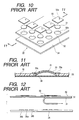
- Fig. 10 is an exploded perspective view of a conventional sheet with plate springs
- Fig. 11 is a sectional view taken on line 11-11 in Fig. 10
- Fig. 12 is an explanatory diagram explaining how to assemble a conventional switch device using the conventional sheet with plate springs.
- Plural movable contacts 31 are each constituted by a thin, dome-like, metallic plate spring and can be displaced with click feeling when a depressing force is exerted thereon from its top portion.
- Film 32 is a generally rectangular, large-sized, somewhat thick film with an adhesive layer affixed to a lower surface thereof.
- the film 32 has plural holes 32a which are formed through upper and lower surfaces of the film and which are each a little larger than each movable contact 31.
- the movable contacts 31 are respectively inserted into the holes 32a.
- a plurality of generally square adhesive sheets 33 which are each a little larger than each hole 32a, are each constituted of a film with an adhesive layer affixed to the whole of its lower surface and are each formed with a through hole 33a generally centrally of one side of the sheet and in the vicinity of the side edge.
- Each adhesive sheet 33 is affixed to an upper surface of each movable contact 31 and also affixed to the surface portion of the film 32 contiguous thereto, thereby fixing the movable contact 31 to the film 32 and holding it on the film.
- the through holes 33a are respectively opposed to the holes 32a of the film with the movable contacts 31 received therein to provide communication of the holes 32a with the exterior.
- a separator 34 is formed by a large-sized film or paper having substantially the same shape as the film 32.
- the separator 34 is affixed to the lower surface of the film 32 through the adhesive layer formed on the film lower surface to protect lower surfaces of the movable contacts 31 so that dust and other foreign matters may not get into the interior of each movable contact dome.
- a sheet 35 with movable contacts a sheet with plate springs.
- the conventional switch device uses the conventional sheet 35 with movable contacts (sheet with plate springs) and includes a large-sized insulating substrate 36.
- the insulating substrate 36 is a flexible substrate constituted of a polyimide film for example, and first and second fixed contacts 36a, 36b are formed on the surface of the insulating substrate 36, for example, by etching copper foil or the like.
- the adhesive layer applied to the lower surface of the film 32 in the sheet 35 with movable contacts is exposed by releasing the separator 34 affixed to the film lower surface, allowing the holes 32a to be opposed to the first and second fixed contacts 36a, 36b, and in this state the film 32 is affixed to an upper surface of the insulating substrate 36 to assemble a switch device.
- the movable contacts 31 are placed on the surface of the insulating substrate 36 in such a manner that the peripheral edge of a lower end portion of each movable contact 31 is constantly in contact with the associated second fixed contacts 36b and that the dome-like top of each movable contact 31 is spaced from and opposed to the associated first fixed contact 36a.
- the air present within the dome of the movable contact 31 flows out from an end portion of the movable contact 31, then passes through the associated hole 32a formed in the film 32 and further through the through hole 33a formed in the associated adhesive sheet 33, and escapes to the exterior.
- the film 32 having holes 32a for fitting therein of the movable contacts 31 (plate springs), as well as plural adhesive sheets 33, are required, the productivity is low, the number of components used increases, the cost becomes high, and the thickness of the switch device increases.
- a sheet with plate springs comprising an adhesive sheet having adhesive portions on one side thereof, a plurality of plate springs each constituted of a deformable metallic plate having resilience and with the adhesive portions affixed to upper surfaces thereof, and a sheet-like separator affixed to the adhesive sheet to protect lower surfaces of the plate springs, wherein the one side of the adhesive sheet is studded with the adhesive portions each in a projected form, and vent portions are formed between the studded and projected adhesive portions and between the plate springs and the exterior of the adhesive sheet so that air can get into and out of the vent portions.
- the second solving means adopted by the invention in combination with the above first means, a sheet with plate springs wherein the total area of the adhesive portions studded and projected on the one side of the adhesive sheet is larger than the total area of the one side portion of the adhesive sheet where the adhesive portions are not projected.
- a switch device comprising an adhesive sheet whose lower surface is studded with adhesive portions, movable contacts constituted by a plurality of plate springs whose upper surfaces are affixed to the adhesive portions, the plate springs each being constituted of a deformable metallic plate having resilience, and an insulating substrate having a plurality of fixed contacts, wherein the adhesive portions studded and projected on the lower surface of the adhesive sheet are affixed to the substrate in a state such that the movable contacts affixed to the adhesive sheet through the adhesive portions are opposed to the fixed contacts of the insulating substrate, and vent portions are formed between the studded and projected adhesive portions and between the movable contacts and the exterior of the adhesive sheet so that air can get into and out of the vent portions.
- the eleventh solving means adopted by the invention there is provided, in combination with the above tenth means, a switch device wherein the total area of the adhesive portions studded and projected on the lower surface of the adhesive sheet is larger than the total area of the lower surface portion of the adhesive sheet where the adhesive portions are not projected.
- the thirteenth solving means adopted by the invention there is provided, in combination with the above tenth means, a switch device wherein the projected adhesive portions each have a polygonal shape and are arranged regularly.
- a switch device wherein the projected adhesive portions each have a generally circular shape and are arranged regularly.
- Fig. 1 is a sectional view of a principal portion of a sheet with plate springs according to the first embodiment of the present invention
- Fig. 2 is a rear view of an adhesive sheet with plate springs affixed thereto, which is used in the first embodiment
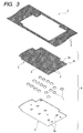
- Fig. 3 is an exploded perspective view showing the construction of the sheet with plate springs according to the first embodiment and also showing a manufacturing method for the sheet.
- Fig. 4 is an enlarged rear view of a principal portion of an adhesive sheet with plate springs affixed thereto, which is used in a sheet with plate springs according to the second embodiment of the present invention
- Fig. 5 is an enlarged rear view of a principal portion of an adhesive sheet with plate springs affixed thereto, which is used in a sheet with plate springs according to the third embodiment of the present invention
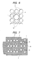
- Fig. 6 is an enlarged rear view of a principal portion of an adhesive sheet with plate springs affixed thereto, which is used in a sheet with plate springs according to the fourth embodiment of the present invention
- Fig. 4 is an enlarged rear view of a principal portion of an adhesive sheet with plate springs affixed thereto, which is used in a sheet with plate springs according to the second embodiment of the present invention
- Fig. 5 is an enlarged rear view of a principal portion of an adhesive sheet with plate springs affixed thereto, which is used in a sheet with plate springs according to the third embodiment
- FIG. 7 is a rear view of an adhesive sheet with plate springs affixed thereto, which is used in a sheet with plate springs according to the fifth embodiment of the present invention
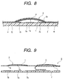
- Fig. 8 is a sectional view of a principal portion of a switch device using a sheet with plate springs according to the present invention
- Fig. 9 is an explanatory diagram explaining how to assemble the switch device.
- Plural movable contacts 1 are each formed of a thin dome-like metallic plate having resilience such as, for example, a thin stainless steel or phosphor bronze plate and can be displaced with click feeling when subjected to a depressing force applied from top portions thereof.
- Each movable contact 1 does not have any through hole in its dome, but is centrally formed with a contact portion la projecting toward the interior of the dome.
- An adhesive sheet 2 is a film about 25 to 100 ⁇ m thick which is formed using a polyester resin for example and which is colored in white, and colored, acrylic adhesive portions 3 are formed on the adhesive sheet 2 to a thickness of about 15 to 35 ⁇ m by printing.
- the adhesive portions 3 are colored in a color (e.g., green) different from the film color (white) of the adhesive sheet 2 by mixing a pigment therein.
- the adhesive sheet 2 possesses slight expanding and contracting properties (flexibility) and is formed with plural holes 2a.
- the adhesive portions 3, which are each in a hexagonal shape as a polygonal shape, are downwardly projected and regularly studded on a lower surface as one side of the adhesive sheet 2. They are arranged in such a honeycomb shape as shown in Figs. 2 and 3.
- Vent portions 4 which will be described later are formed between the projected and studded adhesive portions 3 so as to permit the entry and escape of air between, for example, a central portion of the adhesive sheet 2 and the holes 2a or outer edges 2b of the adhesive sheet.
- the adhesive portions 3 may be arranged not only in such a honeycomb shape as shown in Fig. 2, but also in such a regular shape as the squares of a checkerboard, a concentric shape, or a spiral shape.
- the arrangement of the adhesive portions 3 need not always be regular.
- the total area thereof on one side of the adhesive sheet 2 is larger than the total area of the one side portion of the adhesive sheet where the adhesive portions 3 are not projected, and the area of each of the adhesive portions 3 is smaller than the area of an upper surface of each movable contact 1.
- the spacing between adjacent adhesive portions 3 is set smaller than the size (diameter) of each movable contact (plate spring) 1.
- the adhesive portions 3 may each be formed so as not to cover the upper surface of each movable contact 1 completely. In this case, the area of each adhesive portion 3 may be larger than the area of the upper surface of each movable contact 1.
- the movable contacts 1 are conveyed to a predetermined position on the adhesive sheet 2 by means of a mounter in a state such that their upper surfaces are affixed to the adhesive portions 3 of the adhesive sheet 2 and that their upper surfaces and end portions 1b are positioned at least partially in the vent portions 4.
- a separator 5 is constituted of a transparent polyester film whose shape is substantially the same as the shape of the adhesive sheet 2, and a release agent is applied to an upper surface of the separator 5 so as to permit easy release of the separator from the adhesive sheet 2.
- the separator 5 has plural holes 5a (see Fig. 3) which are formed as through holes extending through upper and lower surfaces of the separator.
- the separator 5 is affixed to the lower surface of the adhesive sheet 2 so that its holes 5a and the holes 2a of the adhesive sheet 2 are superimposed one on the other through the adhesive portion 3 on the adhesive sheet 2.
- the separator 5 sandwiches the movable contacts 1 in between it and the adhesive sheet 2 and protects the lower surface of the movable contacts 1 so that dust and other foreign matters may not get into the domes of the movable contacts 1, thereby constituting a sheet 6 with movable contacts (a sheet with plate springs).
- the separator 5 Since the separator 5 is transparent, the positions of the movable contacts 1 and the presence of foreign matters, if any, can be seen through.
- vent portions 4 are formed between the projected adhesive portions 3 and between the separator 5 and the adhesive sheet 2.
- the vent portions 4 extend from the end portions 1b of the movable contacts 1 and are connected to the holes 2a and the outer edges 2b.
- a band-like adhesive sheet 2 is provided, though the illustrated one is not in a belt form, whose one side is studded with adhesive portions 3 projectingly by screen printing.
- movable contacts 1 are affixed to predetermined positions on the adhesive sheet 2 by means of a mounter and thereafter a belt-like separator 5 having the same shape as the adhesive sheet 2, though the illustrated one is not in a belt form, is affixed to the adhesive tape 2.
- the adhesive tape 2 and the separator 5 are punched simultaneously into a desired shape with use of a punching die.
- the fabrication of the sheet 6 with plate springs as movable contacts is completed in this way.
- holes 2a and 5a for mounting LEDs (light emitting diodes) therein, as well as other holes, etc., if required.
- a transparent polyester film may be used as the base film of the adhesive sheet 2, and a colored (e.g. white or blue) paper (release paper) may be used as the separator 5.
- a colored, translucent sheet if only it can transmit light.
- Fig. 4 illustrates a sheet with plate springs according to the second embodiment of the present invention.
- adhesive portions 3 are studded and projected each in a triangular shape.
- Fig. 5 illustrates a sheet with plate springs according to the third embodiment of the present invention.
- adhesive portions 3 are studded and projected each in a square shape.
- Fig. 6 illustrates a sheet with plate springs according to the fourth embodiment of the present invention.
- studded and projected adhesive portions 3 are each in a hexagonal shape and a small dot-like adhesive portion 3a is disposed in a central portion surrounded with such hexagonal adhesive portions 3.
- Fig. 7 illustrates a sheet with plate springs according to the fifth embodiment of the present invention.
- studded and projected adhesive portions 3 are each in a generally circular shape such as a circle or an ellipse.
- a switch device is illustrated in Figs. 8 and 9.
- This switch device uses the foregoing sheet with movable contacts (sheet with plate springs) 6 and also uses an insulating substrate 7 which is about the same in size as the sheet 6 with movable contacts.
- the insulating substrate 7 is a flexible substrate such as a polyimide film.
- First circular fixed contacts 7a and second C-shaped fixed contacts 7b are formed on the surface of the insulating substrate 7 by etching copper foil, the second fixed contacts 7b being formed so as to surround the first fixed contacts 7a.
- wiring patterns are formed on the surface of the insulating substrate 7 simultaneously with the formation of the first and second fixed contacts 7a, 7b.
- Chip LEDs are connected to predetermined wiring patterns by soldering or any other suitable means.
- the insulating substrate 7 may be a polyester film and the first and second fixed contacts 7a, 7b may be conductive patterns such as silver patterns formed by printing or may even be formed by etching copper foil on a rigid substrate such as a glass-contained epoxy substrate.
- the movable contacts 1 are placed on the surface of the insulating substrate 7 while the peripheral edges of their end portions 1b are constantly in contact with the second fixed contacts 7b. Further, the chip LEDs (not shown) mounted to the insulating substrate 7 are projected from the holes 2a of the adhesive sheet 2.
- an operating panel section with illumination in a portable telephone set for example, in which the chip LEDs function to illuminate operating members (operating buttons) (not shown) which are for depressing the movable contacts 1.
- Vent portions 4 are formed between the projected adhesive portions 3 and between the adhesive sheet 2 and the insulating substrate 7.
- the vent portions 4 extend from the end portions 1b of the movable contacts 1 and are connected to the holes 2a and outer edges 2b.
- the air present within the dome of the movable contact 1 flows out from the end portions 1b of the movable contact 1, then passes through the vent portions 4 and escapes to the exterior from the holes 2a formed in the adhesive sheet 2 or from the outer edges 2b of the adhesive sheet 2.
- the upper portion (contact portion 1a) of the movable contact 1 leaves the first fixed contact 7a, making the first and second fixed contacts 7a, 7b non-conductive, i.e., turning them OFF.
- one side of the adhesive sheet 2 is studded with projected adhesive portions 3, and vent portions 4 are formed between the thus studded and projected adhesive portions 3 and between the deformable plate spring 1 as a movable contact and the exterior of the adhesive sheet 2, to permit the entry and discharge of air. Therefore, the whole upper and lower surfaces of the plate springs (movable contacts 1) can be covered with both adhesive sheet 2 and separator 5 and thus it is possible to provide a sheet with plate springs capable of preventing the entry of dust and other foreign matters.
- the separator 5 is attached directly to the adhesive sheet 2, it is not necessary to use such adhesive films 33 as in the prior art, thus permitting the provision of a less expensive sheet with plate springs.
- the total area of the adhesive portions 3 studded and projected on one side of the adhesive sheet 2 is larger than the total area of the one side portion of the adhesive sheet where the adhesive portions 3 are not projected, there is obtained a large adhesive area and it is possible to provide a sheet with plate springs which permits the plate springs (movable contacts 1) to be adhered to the adhesive sheet 2 positively.
- each of the studded and projected adhesive portions 3 is set smaller than the area of the upper surface of each plate spring (movable contact 1), the adhesive portion 3 do not cover the whole circumference of the end portion 1b of each plate spring (movable contact 1), thus ensuring the vent portions 4 from the plate spring (movable contact 1).
- the spacing between adjacent projected adhesive portions 3 is set smaller than the size of each plate spring (movable contact 1), even when the plate springs (movable contacts 1) are affixed to arbitrary positions, it is not necessary to separately provide a new adhesive sheet 2 and thus it is possible to provide a sheet with plate springs which is versatile and which can cope with various requests.
- the adhesive portions 3 are colored, it is possible to visually check whether the adhesive portions are formed in a desired shape or not after their formation by printing for example. Thus, it becomes easy to check the quality of the adhesive portions 3.
- the area of each adhesive portion 3 which contributes to adhesion can be made large, thereby ensuring the adhesion of the plate springs (movable contacts 1).
- the adhesion of the plate springs (movable contacts 1) can be further ensured.
- the adhesive portions 3 When the projected adhesive portions 3 are each in a hexagonal shape, the adhesive portions 3 can be formed in such a manner that vent portions 4 get in between two adhesive portions 3 in rows adjacent to each other so as to be formed in a zigzag fashion, thus further ensuring the adhesion of the plate springs (movable contacts 1).
- the projected adhesive portions 3 are each formed in a generally circular shape, there is obtained a combination of circular shapes in case of using dome-like plate springs (movable contacts 1), thereby ensuring adhesion of the plate springs (movable contacts 1) and ensuring the formation of vent portions 4.
- the adhesive portions 3 regularly it is possible to further ensure the adhesion of the plate springs (movable contacts 1).
- either the adhesive sheet 2 or the separator 5 is made transparent or translucent and the other opaque, it is possible to find out a positional displacement of a plate spring (movable contact 1) and the presence of dust easily visually, thus facilitating the inspection of quality.
- the adhesive portions 3 which are studded and projected on the lower surface of the adhesive sheet 2 in a state such that the movable contacts 1 each constituted of a plate spring are opposed to the fixed contacts 7a and 7b, and vent portions 4 are formed between the studded and projected adhesive portions 3 and between the movable contacts 1 and the exterior of the adhesive sheet 2, to permit the entry and discharge of air.
- the whole upper and lower surfaces of the movable contacts 1 can be covered with the adhesive sheet 2 and the insulating substrate 7; in other words, it is possible to provide a switch device which can prevent the entry of dust and other foreign matters and which is strong against static electricity.
- the separator 5 is attached directly to the adhesive sheet 2, it is not required to use such a film 32 as in the prior art, thus permitting the provision of a less expensive switch device.
- the total area of the adhesive portions 3 which are studded and projected on the lower surface of the adhesive sheet 2 is set larger than the total area of the lower surface portion of adhesive sheet where the adhesive portions 3 are not projected, there is obtained a large area for adhesion and it is possible to provide a switch device wherein the adhesive sheet 2 can be firmly adhered to the movable contacts 1 and the insulating substrate 7.
- each of the studded and projected adhesive portions 3 is set smaller than the area of the upper surface of each movable contact 1, the adhesive portion 3 does not cover the whole circumference of the end portion 1b of the movable contact 1, thus permitting the provision of a switch device which can ensure the formation of vent portions 4 from the movable contacts 1.
- the projected adhesive portions 3 are each in a polygonal shape, the area of each adhesive portion 3 which contributes to the adhesion can be made large, thereby ensuring the adhesion of the plate springs (movable contacts 1).
- the adhesive portions 3 regularly, it is possible to provide a switch device wherein the adhesion of the plate springs (movable contacts 1) can be further ensured.
- the adhesive portions 3 are each in a hexagonal shape, the adhesive portions 3 can be formed in such a manner that vent portions 4 get in between two adhesive portions 3 in rows adjacent to each other so as to be formed in a zigzag fashion, thus permitting the provision of a switch device which can further ensure the adhesion of the plate springs (movable contacts 1).
- the projected adhesive portions 3 are each formed in a generally circular shape, there is obtained a combination of circular shapes in case of using dome-like plate springs (movable contacts 1), thereby ensuring the adhesion of the plate springs (movable contacts 1) and ensuring the formation of vent portions 4.
- the adhesive portions 3 by arranging the adhesive portions 3 regularly, it is possible to provide a switch device which can further ensure the adhesion of the plate springs (movable contacts 1).
Landscapes
- Push-Button Switches (AREA)
Applications Claiming Priority (4)
| Application Number | Priority Date | Filing Date | Title |
|---|---|---|---|
| JP2000079340 | 2000-03-16 | ||
| JP2000079340 | 2000-03-16 | ||
| JP2000337263 | 2000-10-31 | ||
| JP2000337263 | 2000-10-31 |
Publications (3)
| Publication Number | Publication Date |
|---|---|
| EP1137028A2 true EP1137028A2 (fr) | 2001-09-26 |
| EP1137028A3 EP1137028A3 (fr) | 2004-03-24 |
| EP1137028B1 EP1137028B1 (fr) | 2008-11-05 |
Family
ID=26588017
Family Applications (1)
| Application Number | Title | Priority Date | Filing Date |
|---|---|---|---|
| EP01302120A Expired - Lifetime EP1137028B1 (fr) | 2000-03-16 | 2001-03-08 | Feuille avec disques élastiques et dispositif de commutation utilisant cette feuille |
Country Status (6)
| Country | Link |
|---|---|
| US (1) | US6548778B2 (fr) |
| EP (1) | EP1137028B1 (fr) |
| KR (1) | KR100403433B1 (fr) |
| CN (1) | CN1222968C (fr) |
| DE (1) | DE60136406D1 (fr) |
| TW (1) | TW503415B (fr) |
Cited By (4)
| Publication number | Priority date | Publication date | Assignee | Title |
|---|---|---|---|---|
| EP1199736A4 (fr) * | 2000-04-18 | 2003-03-05 | Mitsumi Electric Co Ltd | Commutateur a membrane |
| EP1881512A3 (fr) * | 2006-07-20 | 2008-03-05 | Polymatech Co., Ltd. | Feuille à touches |
| EP2043124A1 (fr) * | 2007-09-28 | 2009-04-01 | Research In Motion Limited | Clavier pour dispositif sans fil |
| US8836546B2 (en) | 2007-09-28 | 2014-09-16 | Blackberry Limited | Keypad for a wireless device |
Families Citing this family (11)
| Publication number | Priority date | Publication date | Assignee | Title |
|---|---|---|---|---|
| JP3931570B2 (ja) | 2001-02-16 | 2007-06-20 | 松下電器産業株式会社 | 可動接点体の製造方法 |
| JP2003151393A (ja) * | 2001-11-15 | 2003-05-23 | Matsushita Electric Ind Co Ltd | 可動接点体およびそれを用いたパネルスイッチ、並びにそのパネルスイッチを装着した電子機器 |
| JP3808073B2 (ja) * | 2003-12-05 | 2006-08-09 | シチズン電子株式会社 | キーシートモジュール |
| JP2005209616A (ja) * | 2003-12-25 | 2005-08-04 | Alps Electric Co Ltd | 可動接点付シート及びこれを用いた押釦スイッチ |
| JP4466284B2 (ja) * | 2004-08-27 | 2010-05-26 | パナソニック株式会社 | 可動接点体連の製造方法 |
| US7145092B2 (en) * | 2005-02-25 | 2006-12-05 | Nokia Corporation | Keyboard structure |
| JP2006294429A (ja) * | 2005-04-12 | 2006-10-26 | Matsushita Electric Ind Co Ltd | 可動接点体およびそれを用いて構成されたパネルスイッチ |
| US7946720B2 (en) * | 2007-11-22 | 2011-05-24 | Panasonic Corporation | Light guide sheet, movable contact structure using the light guide sheet, method of manufacturing the movable contact structure, and switch using the light guide sheet and the movable contact structure |
| US7687735B2 (en) * | 2008-05-30 | 2010-03-30 | Sipix Technology Inc. | Packaging structure for depression switches |
| CN101777451B (zh) * | 2009-01-13 | 2013-01-23 | 富士康(昆山)电脑接插件有限公司 | 按钮开关 |
| CN101872691B (zh) * | 2009-04-21 | 2013-05-29 | 深圳富泰宏精密工业有限公司 | 按键组件及具有该按键组件的便携式电子装置 |
Family Cites Families (9)
| Publication number | Priority date | Publication date | Assignee | Title |
|---|---|---|---|---|
| US4018999A (en) * | 1974-09-12 | 1977-04-19 | Mohawk Data Sciences Corporation | Keyboard switch assembly having adhesive position retainer element |
| US4046975A (en) * | 1975-09-22 | 1977-09-06 | Chomerics, Inc. | Keyboard switch assembly having internal gas passages preformed in spacer member |
| US4071718A (en) * | 1976-10-22 | 1978-01-31 | Bowmar Instrument Corporation | Flat keyboard assembly having cover type membrane with protrusions to align switch components |
| JP2844736B2 (ja) * | 1989-10-25 | 1999-01-06 | 松下電器産業株式会社 | パネルスチッチおよびその製造法 |
| AU663640B2 (en) * | 1993-02-22 | 1995-10-12 | Illinois Tool Works Inc. | Membrane switch |
| JPH08203381A (ja) * | 1995-01-30 | 1996-08-09 | Mitsumi Electric Co Ltd | メンブレンスイッチ |
| JP3988203B2 (ja) * | 1996-10-22 | 2007-10-10 | 松下電器産業株式会社 | パネルスイッチ用可動接点体 |
| JP3046777B2 (ja) * | 1997-03-19 | 2000-05-29 | 北陸電気工業株式会社 | プッシュオン式スイッチを備えた基板 |
| JP3010151B2 (ja) * | 1997-09-22 | 2000-02-14 | 北陸電気工業株式会社 | プッシュオン式スイッチ |
-
2001
- 2001-02-08 TW TW090102773A patent/TW503415B/zh not_active IP Right Cessation
- 2001-03-08 EP EP01302120A patent/EP1137028B1/fr not_active Expired - Lifetime
- 2001-03-08 DE DE60136406T patent/DE60136406D1/de not_active Expired - Lifetime
- 2001-03-13 US US09/805,095 patent/US6548778B2/en not_active Expired - Fee Related
- 2001-03-13 CN CNB011096055A patent/CN1222968C/zh not_active Expired - Lifetime
- 2001-03-15 KR KR10-2001-0013442A patent/KR100403433B1/ko not_active Expired - Fee Related
Cited By (5)
| Publication number | Priority date | Publication date | Assignee | Title |
|---|---|---|---|---|
| EP1199736A4 (fr) * | 2000-04-18 | 2003-03-05 | Mitsumi Electric Co Ltd | Commutateur a membrane |
| EP1881512A3 (fr) * | 2006-07-20 | 2008-03-05 | Polymatech Co., Ltd. | Feuille à touches |
| US7598466B2 (en) | 2006-07-20 | 2009-10-06 | Polymatech Co., Ltd. | Key sheet |
| EP2043124A1 (fr) * | 2007-09-28 | 2009-04-01 | Research In Motion Limited | Clavier pour dispositif sans fil |
| US8836546B2 (en) | 2007-09-28 | 2014-09-16 | Blackberry Limited | Keypad for a wireless device |
Also Published As
| Publication number | Publication date |
|---|---|
| US6548778B2 (en) | 2003-04-15 |
| EP1137028A3 (fr) | 2004-03-24 |
| EP1137028B1 (fr) | 2008-11-05 |
| TW503415B (en) | 2002-09-21 |
| CN1222968C (zh) | 2005-10-12 |
| KR20010090440A (ko) | 2001-10-18 |
| DE60136406D1 (de) | 2008-12-18 |
| US20010022270A1 (en) | 2001-09-20 |
| KR100403433B1 (ko) | 2003-10-30 |
| CN1314688A (zh) | 2001-09-26 |
Similar Documents
| Publication | Publication Date | Title |
|---|---|---|
| US6548778B2 (en) | Sheet with plate springs and switch device using same | |
| JP3808073B2 (ja) | キーシートモジュール | |
| CN100511530C (zh) | 用于便携式设备的具有按键支撑结构的键盘 | |
| JP2008060058A (ja) | 発光シートモジュール | |
| US8232491B2 (en) | Movable contact element and switch using the same | |
| US8388157B2 (en) | Light guide sheet and movable contact assembly including the same | |
| JP2004014284A (ja) | 照光スイッチシート及びこれを用いた照光ユニット | |
| KR100380302B1 (ko) | 가동접점부착시트 및 이 가동접점부착시트를 사용한스위치장치 | |
| JP3938846B2 (ja) | 板バネ付シート、及びこの板バネ付シートを用いたスイッチ装置 | |
| JP4295789B2 (ja) | 板バネ付シート | |
| JP4439418B2 (ja) | 機能性表示シート及びその製造方法及びこれを用いたスイッチの製造方法 | |
| US20060225996A1 (en) | Movable contact element and panel switch formed using the same | |
| KR100397114B1 (ko) | 시트형상 스위치 | |
| CN101634430B (zh) | 导光片以及使用该导光片的可动触点体 | |
| JP4486012B2 (ja) | スイッチ装置 | |
| CN100587880C (zh) | 带接点薄片及输入装置 | |
| US20100187077A1 (en) | Movable contact unit and switch using the same | |
| JP2007305385A (ja) | 押釦スイッチおよびこの押釦スイッチの作製に用いられる接点ばね付きシート | |
| JP2006127799A (ja) | 板ばね付きシート及びこれを用いたスイッチ装置 | |
| JPS6366590A (ja) | 電子機器用操作パネル | |
| JP2001043763A (ja) | 可動接点及びこの可動接点を用いたスイッチ装置 | |
| JP2011238498A (ja) | 導光シート及びこれを用いた可動接点体 | |
| JP2010027325A (ja) | 可動接点体及びこれを用いたスイッチ | |
| KR20070063613A (ko) | 이동통신단말기의 키패드 조립체 | |
| JP2010212123A (ja) | 導光シート及びこれを用いた可動接点体 |
Legal Events
| Date | Code | Title | Description |
|---|---|---|---|
| PUAI | Public reference made under article 153(3) epc to a published international application that has entered the european phase |
Free format text: ORIGINAL CODE: 0009012 |
|
| AK | Designated contracting states |
Kind code of ref document: A2 Designated state(s): AT BE CH CY DE DK ES FI FR GB GR IE IT LI LU MC NL PT SE TR |
|
| AX | Request for extension of the european patent |
Free format text: AL;LT;LV;MK;RO;SI |
|
| PUAL | Search report despatched |
Free format text: ORIGINAL CODE: 0009013 |
|
| AK | Designated contracting states |
Kind code of ref document: A3 Designated state(s): AT BE CH CY DE DK ES FI FR GB GR IE IT LI LU MC NL PT SE TR |
|
| AX | Request for extension of the european patent |
Extension state: AL LT LV MK RO SI |
|
| 17P | Request for examination filed |
Effective date: 20040503 |
|
| AKX | Designation fees paid |
Designated state(s): DE FI FR GB SE |
|
| 17Q | First examination report despatched |
Effective date: 20061201 |
|
| GRAP | Despatch of communication of intention to grant a patent |
Free format text: ORIGINAL CODE: EPIDOSNIGR1 |
|
| GRAS | Grant fee paid |
Free format text: ORIGINAL CODE: EPIDOSNIGR3 |
|
| GRAA | (expected) grant |
Free format text: ORIGINAL CODE: 0009210 |
|
| AK | Designated contracting states |
Kind code of ref document: B1 Designated state(s): DE FI FR GB SE |
|
| REG | Reference to a national code |
Ref country code: GB Ref legal event code: FG4D |
|
| REF | Corresponds to: |
Ref document number: 60136406 Country of ref document: DE Date of ref document: 20081218 Kind code of ref document: P |
|
| PG25 | Lapsed in a contracting state [announced via postgrant information from national office to epo] |
Ref country code: FI Free format text: LAPSE BECAUSE OF FAILURE TO SUBMIT A TRANSLATION OF THE DESCRIPTION OR TO PAY THE FEE WITHIN THE PRESCRIBED TIME-LIMIT Effective date: 20081105 |
|
| PG25 | Lapsed in a contracting state [announced via postgrant information from national office to epo] |
Ref country code: SE Free format text: LAPSE BECAUSE OF FAILURE TO SUBMIT A TRANSLATION OF THE DESCRIPTION OR TO PAY THE FEE WITHIN THE PRESCRIBED TIME-LIMIT Effective date: 20090205 |
|
| PLBE | No opposition filed within time limit |
Free format text: ORIGINAL CODE: 0009261 |
|
| STAA | Information on the status of an ep patent application or granted ep patent |
Free format text: STATUS: NO OPPOSITION FILED WITHIN TIME LIMIT |
|
| 26N | No opposition filed |
Effective date: 20090806 |
|
| PGFP | Annual fee paid to national office [announced via postgrant information from national office to epo] |
Ref country code: FR Payment date: 20100318 Year of fee payment: 10 |
|
| PGFP | Annual fee paid to national office [announced via postgrant information from national office to epo] |
Ref country code: GB Payment date: 20100208 Year of fee payment: 10 |
|
| PGFP | Annual fee paid to national office [announced via postgrant information from national office to epo] |
Ref country code: DE Payment date: 20100331 Year of fee payment: 10 |
|
| GBPC | Gb: european patent ceased through non-payment of renewal fee |
Effective date: 20110308 |
|
| REG | Reference to a national code |
Ref country code: FR Ref legal event code: ST Effective date: 20111130 |
|
| PG25 | Lapsed in a contracting state [announced via postgrant information from national office to epo] |
Ref country code: FR Free format text: LAPSE BECAUSE OF NON-PAYMENT OF DUE FEES Effective date: 20110331 Ref country code: DE Free format text: LAPSE BECAUSE OF NON-PAYMENT OF DUE FEES Effective date: 20111001 |
|
| PG25 | Lapsed in a contracting state [announced via postgrant information from national office to epo] |
Ref country code: GB Free format text: LAPSE BECAUSE OF NON-PAYMENT OF DUE FEES Effective date: 20110308 |
|
| REG | Reference to a national code |
Ref country code: DE Ref legal event code: R119 Ref document number: 60136406 Country of ref document: DE Effective date: 20111001 |