EP1137152A2 - Moteur équippé d'un ventilateur et avec une structure réduisant le niveau de bruit - Google Patents
Moteur équippé d'un ventilateur et avec une structure réduisant le niveau de bruit Download PDFInfo
- Publication number
- EP1137152A2 EP1137152A2 EP01105664A EP01105664A EP1137152A2 EP 1137152 A2 EP1137152 A2 EP 1137152A2 EP 01105664 A EP01105664 A EP 01105664A EP 01105664 A EP01105664 A EP 01105664A EP 1137152 A2 EP1137152 A2 EP 1137152A2
- Authority
- EP
- European Patent Office
- Prior art keywords
- vent holes
- yoke
- fan
- blades
- slots
- Prior art date
- Legal status (The legal status is an assumption and is not a legal conclusion. Google has not performed a legal analysis and makes no representation as to the accuracy of the status listed.)
- Withdrawn
Links
Images


Classifications
-
- H—ELECTRICITY
- H02—GENERATION; CONVERSION OR DISTRIBUTION OF ELECTRIC POWER
- H02K—DYNAMO-ELECTRIC MACHINES
- H02K9/00—Arrangements for cooling or ventilating
- H02K9/02—Arrangements for cooling or ventilating by ambient air flowing through the machine
- H02K9/04—Arrangements for cooling or ventilating by ambient air flowing through the machine having means for generating a flow of cooling medium
- H02K9/06—Arrangements for cooling or ventilating by ambient air flowing through the machine having means for generating a flow of cooling medium with fans or impellers driven by the machine shaft
-
- H—ELECTRICITY
- H02—GENERATION; CONVERSION OR DISTRIBUTION OF ELECTRIC POWER
- H02K—DYNAMO-ELECTRIC MACHINES
- H02K5/00—Casings; Enclosures; Supports
- H02K5/04—Casings or enclosures characterised by the shape, form or construction thereof
- H02K5/20—Casings or enclosures characterised by the shape, form or construction thereof with channels or ducts for flow of cooling medium
- H02K5/207—Casings or enclosures characterised by the shape, form or construction thereof with channels or ducts for flow of cooling medium with openings in the casing specially adapted for ambient air
-
- H—ELECTRICITY
- H02—GENERATION; CONVERSION OR DISTRIBUTION OF ELECTRIC POWER
- H02K—DYNAMO-ELECTRIC MACHINES
- H02K1/00—Details of the magnetic circuit
- H02K1/06—Details of the magnetic circuit characterised by the shape, form or construction
- H02K1/22—Rotating parts of the magnetic circuit
- H02K1/26—Rotor cores with slots for windings
Definitions
- the present invention relates to a motor having a rotor equipped with a cooling fan.
- One previously proposed rotor of a motor has a rotatable shaft to which an armature, a commutator and a cooling fan (hereinafter simply referred to as a fan) are secured.
- the rotor is substantially contained in a yoke.
- the yoke has a plurality of vent holes that communicate an interior of the yoke with an exterior of the yoke. These vent holes are disposed adjacent the fan.
- the number of slots formed in a core of the armature, the number of blades of the fan and the number of vent holes are set to twelve, six and eighteen, respectively.
- vibrations are generated as shown in FIG. 8.
- vibrations generated during movement of the slots across a magnetic field show peaks at 12 Hz (primary vibration), 24 Hz, 36 Hz, and so on.
- vibrations generated on the blade side during movement of the blades over the adjacent vent holes show peaks at 6 Hz, 12 Hz, 18 Hz, 24 Hz, 30 Hz, 36 Hz, and so on.
- the number of vent holes is eighteen, the vibrations generated on the vent hole side during the movement of the blades over the adjacent vent holes show peaks at 18 Hz, 36 Hz, and so on.
- All of these vibrations i.e., vibrations generated at the slots, the blades and the vent holes
- are added together i.e., resonate together
- a predetermined frequency range audible frequency range of generally between 16 Hz and 20 KHz
- a noise level of the motor disadvantageously increases.
- a motor including a rotatable shaft, a core secured to the rotatable shaft, a fan secured to the rotatable shaft, and a yoke containing the core and the fan.
- the core has a plurality of slots around which a coil is wound.
- the fan has a plurality of blades.
- the yoke has a plurality of vent holes that communicate an interior of the yoke with an exterior of the yoke.
- the plurality of the vent holes are arranged adjacent the fan.
- the number of slots, the number of blades and the number of vent holes can be set such that the number of slots, the number of blades and the number of vent holes do not share a common divisor other than 1.
- only the number of slots and the number of vent holes can be set such that the number of slots and the number of vent holes do not share a common divisor other than 1. Furthermore, only the number of blades and the number of vent holes can be set such that the number of blades and the number of vent holes do not share a common divisor other than 1.
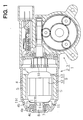
- a motor 1 includes a motor main body 2 and a speed reducing unit 3 secured to the motor main body 2.
- the motor main body 2 includes a yoke housing (hereinafter simply referred to as a yoke) 4, a plurality of magnets 5 secured to an inner peripheral surface of the yoke 4, and a rotor 6 substantially contained within the yoke 4.
- the yoke 4 has a generally cylindrical body including a bottom wall (left side in FIG. 1 ) and an open end (right side in FIG 1 ) . At the bottom side of the yoke 4, there is provided a reduced diameter portion 4a that is tapered toward its end.
- a plurality in FIG.
- vent holes 4b are circumferentially arranged at substantially equal angular intervals in the reduced diameter portion 4a to communicate an interior of the yoke 4 with an exterior of the yoke 4.
- the vent holes 4b are all of substantially the same size and shape. In the present embodiment, as shown in FIG. 4, thirteen vent holes 4b are provided.
- a cylindrical flange 4c At a center of the bottom wall of the yoke 4, there is formed a cylindrical flange 4c that protrudes toward the interior of the yoke 4. The cylindrical flange 4c receives and holds a bearing 7.
- the rotor 6 includes a rotatable shaft 8, an armature 9, a commutator 10 and a cooling fan (hereinafter simply referred to as a fan) 11.
- a base end of the rotatable shaft 8 is rotatably supported by the bearing 7.
- the armature 9 includes a core 12 and a coil (winding) 13 wound around the core 12.
- the armature 9 is secured to the middle of the rotatable shaft 8 such that the armature 9 faces the magnets 5.
- the core 12 has a plurality of slots 12b circumferentially arranged between teeth 12a at substantially equal angular intervals.
- the slots 12a are all of substantially the same size and shape. In the present embodiment, as shown in FIG. 2, twelve slots 12b are provided.
- the commutator 10 is secured to a distal end portion (distal to the armature 9) of the rotatable shaft 8. Adjacent to the vent holes 4b of the yoke 4, the fan 11 is secured to the base end portion of the rotatable shaft 8 between the bearing 7 and the armature 9.
- the fan 11 is made of a resin material and includes a cylindrical portion 11a received and secured around the rotatable shaft 8, an annular portion 11b generally radially outwardly extending from the cylindrical portion 11a, and a plurality of blades 11c axially protruding (toward the right side of FIG. 1) from the annular portion 11b.
- the blades 11c are circumferentially arranged about the shaft 8 at substantially equal angular intervals.
- the blades 11c are all of substantially the same size and shape. In the present embodiment, as shown in FIG. 3, eleven blades 11c are provided.
- the number (twelve in this embodiment) of slots 12b, the number (eleven in this embodiment) of blades 11c and the number (thirteen in this embodiment) of vent holes 4b are set such that these three numbers do not share a common divisor other than 1.
- vibrations are generated as shown in FIG. 5. More specifically, due to the fact that the number of slots 12b is twelve, vibrations generated during the movement of the slots 12b (teeth 12a) across the magnetic field (adjacent the magnets 5) show peaks at 12 Hz, 24 Hz, 36 Hz, 48Hz and so on. Furthermore, due to the fact that the number of blades 11c is eleven, vibrations generated on the blade 11c side (fan 11) during the movement of the blades 11c over the adjacent vent holes 4b show peaks at 11 Hz, 22 Hz, 33 Hz, 44 Hz, and so on.
- vent hole 4b due to the fact that the number of vent holes 4b is thirteen, the vibrations generated on the vent hole 4b side (yoke 4) during the movement of the blades 11c over the adjacent vent holes 4b show peaks at 13 Hz, 26 Hz, 39 Hz, and so on.
- FIG. 5 is a characteristic diagram that only shows the frequencies up to 50 Hz, so that none of the resonance frequencies at which all of the vibrations are added together (i.e., resonate together) is shown in FIG. 5. Contrary to this, in the previously proposed motor, all of the vibrations are added together (i.e., resonate together) at every 36 Hz, as shown in FIG 8.
- the number of resonance frequencies at which the vibrations generated at the slots 12b, the vibrations generated at the blades 11c and the vibrations generated at the vent holes 4b are added together is thus reduced within the predetermined frequency range (audible frequency range of generally between 16 Hz and 20 KHz). This results in a reduced noise level of the motor.
- the number of slots 12b, the number of blades 11c and the number of vent holes 4b are set to twelve, eleven and thirteen, respectively.
- these numbers can be changed to any numbers as long as they do not share a common divisor other than 1.
- these numbers can be modified as follows. That is, the number of slots 12 can be twelve like that of the above embodiment.
- the number of blades 21 can be thirteen as shown in FIG. 6.
- the number of slots 12b, the number of blades 11c and the number of vent holes 4b are set such that these three numbers do not share a common divisor other than 1 in the above embodiment, this arrangement can be modified as follows. That is, only the number of slots and the number of blades can be set such that these two numbers do not share a common divisor other than 1, and the number of vent holes can be any number. In such a case, it is possible to vary the position, size and/or shape of each vent hole, as desired. For instance, the vent holes may be randomly arranged in the yoke.
- the number of slots and the number of vent holes can be set such that these two numbers do not share a common divisor other than 1, and the number of blades can be any number. Even with such an arrangement, there is the reduced number of resonance frequencies at which the vibrations generated at the slots and the vibrations generated at the vent holes are added together (i.e., resonate together) within the predetermined frequency range. This results in a reduced noise level of the motor (rotor).
- the number of blades and the number of vent holes can be set such that these two numbers do not share a common divisor other than 1, and the number of slots can be any number. Even with such an arrangement, there is the reduced number of resonance frequencies at which the vibrations generated at the blades and the vibrations generated at the vent holes are added together (i.e., resonate together) within the predetermined frequency range. This results in a reduced noise level of the motor (rotor).
- vent holes are disclosed in the accompanying drawings, the vent holes may have any geometrical shapes, such as elongated shapes, triangular shapes, fan shapes, oblong shapes, rectangular shapes or the like.
- a motor (1) includes a rotatable shaft (8), a core (12) secured to the rotatable shaft (8), a fan (11) secured to the rotatable shaft (8), and a yoke (4) containing the core (12) and the fan (11).
- the core (12) has a plurality of slots (12b) around which a coil (13) is wound.
- the fan (11) has a plurality of blades (11c, 21).
- the yoke (4) has a plurality of vent holes (4b) that communicate an interior of the yoke (4) with an exterior of the yoke (4).
- the plurality of the vent holes (4b, 22) are arranged adjacent the fan (11).
- the number of slots (12b), the number of blades (11c, 21) and the number of vent holes (4b, 22) are set such that these three numbers do not share a common divisor other than 1.
Landscapes
- Engineering & Computer Science (AREA)
- Power Engineering (AREA)
- Motor Or Generator Cooling System (AREA)
- Iron Core Of Rotating Electric Machines (AREA)
Applications Claiming Priority (2)
| Application Number | Priority Date | Filing Date | Title |
|---|---|---|---|
| JP2000083914A JP2001275309A (ja) | 2000-03-24 | 2000-03-24 | モータ |
| JP2000083914 | 2000-03-24 |
Publications (2)
| Publication Number | Publication Date |
|---|---|
| EP1137152A2 true EP1137152A2 (fr) | 2001-09-26 |
| EP1137152A3 EP1137152A3 (fr) | 2004-01-28 |
Family
ID=18600470
Family Applications (1)
| Application Number | Title | Priority Date | Filing Date |
|---|---|---|---|
| EP01105664A Withdrawn EP1137152A3 (fr) | 2000-03-24 | 2001-03-07 | Moteur équippé d'un ventilateur et avec une structure réduisant le niveau de bruit |
Country Status (3)
| Country | Link |
|---|---|
| US (1) | US6380647B2 (fr) |
| EP (1) | EP1137152A3 (fr) |
| JP (1) | JP2001275309A (fr) |
Cited By (1)
| Publication number | Priority date | Publication date | Assignee | Title |
|---|---|---|---|---|
| EP3813235A4 (fr) * | 2018-05-11 | 2022-02-09 | Hitachi Industrial Products, Ltd. | Machine électrique rotative |
Families Citing this family (12)
| Publication number | Priority date | Publication date | Assignee | Title |
|---|---|---|---|---|
| US9267512B2 (en) | 2011-10-24 | 2016-02-23 | Hamilton Sundstrand Corporation | Ram air fan diffuser with perforated side walls |
| US9188136B2 (en) | 2011-10-24 | 2015-11-17 | Hamilton Sundstrand Corporation | Fan rotor with cooling holes |
| US8961127B2 (en) | 2011-10-24 | 2015-02-24 | Hamilton Sundstrand Corporation | Shaft cap |
| US8882454B2 (en) | 2011-10-24 | 2014-11-11 | Hamilton Sundstrand Corporation | Ram air fan bearing housing |
| US8887486B2 (en) | 2011-10-24 | 2014-11-18 | Hamilton Sundstrand Corporation | Ram air fan inlet housing |
| US9028220B2 (en) | 2011-10-24 | 2015-05-12 | Hamilton Sundstrand Corporation | Tie rod |
| US9057386B2 (en) | 2011-10-24 | 2015-06-16 | Hamilton Sundstrand Corporation | Ram air fan inner housing |
| US9140272B2 (en) | 2011-10-24 | 2015-09-22 | Hamilton Sundstrand Corporation | Ram air fan outer housing |
| US9228593B2 (en) | 2012-08-15 | 2016-01-05 | Hamilton Sundstrand Corporation | Ram air fan outer housing |
| US9556885B2 (en) | 2012-08-23 | 2017-01-31 | Hamilton Sundstrand Corporation | Inlet shroud assembly |
| CN103236750A (zh) * | 2013-04-23 | 2013-08-07 | 江苏神驰机电有限公司 | 配备冷却风扇的电机转子 |
| US10982682B2 (en) | 2018-03-16 | 2021-04-20 | Hamilton Sundstrand Corporation | Fan rotor for ram air fan |
Family Cites Families (5)
| Publication number | Priority date | Publication date | Assignee | Title |
|---|---|---|---|---|
| GB2227793B (en) * | 1985-11-08 | 1990-10-31 | Papst Motoren Gmbh & Co Kg | Miniature axial fan |
| JP2622215B2 (ja) * | 1991-10-15 | 1997-06-18 | 三菱電機株式会社 | 車両用交流発電機 |
| JP3186239B2 (ja) * | 1992-09-04 | 2001-07-11 | 松下電器産業株式会社 | ブラシレスモータ |
| JPH09289756A (ja) * | 1996-04-22 | 1997-11-04 | Denso Corp | 交流発電機 |
| JP2000166179A (ja) | 1998-12-01 | 2000-06-16 | Brother Ind Ltd | ファン冷却型モータ |
-
2000
- 2000-03-24 JP JP2000083914A patent/JP2001275309A/ja active Pending
-
2001
- 2001-02-27 US US09/793,531 patent/US6380647B2/en not_active Expired - Fee Related
- 2001-03-07 EP EP01105664A patent/EP1137152A3/fr not_active Withdrawn
Cited By (1)
| Publication number | Priority date | Publication date | Assignee | Title |
|---|---|---|---|---|
| EP3813235A4 (fr) * | 2018-05-11 | 2022-02-09 | Hitachi Industrial Products, Ltd. | Machine électrique rotative |
Also Published As
| Publication number | Publication date |
|---|---|
| US20010024072A1 (en) | 2001-09-27 |
| US6380647B2 (en) | 2002-04-30 |
| JP2001275309A (ja) | 2001-10-05 |
| EP1137152A3 (fr) | 2004-01-28 |
Similar Documents
| Publication | Publication Date | Title |
|---|---|---|
| US6380647B2 (en) | Motor having rotor equipped with cooling fan | |
| JP2018125920A (ja) | アウターロータ型モータ | |
| JP2025123342A (ja) | モータ | |
| EP1536142B1 (fr) | Groupe moto-ventilateur | |
| US6617717B2 (en) | Alternator | |
| JP4238093B2 (ja) | モータの支持構造 | |
| US20030001449A1 (en) | Dynamo-electric machine having tapered magnets secured to yoke | |
| US3848145A (en) | Electric motor ventilation | |
| EP3456978B1 (fr) | Dispositif de soufflage | |
| KR20080026874A (ko) | 외전형 팬모터 및 외전형 팬모터용 자석의 착자방법 | |
| JP2003037960A (ja) | アウタロータ型多極発電機 | |
| JP3056174B2 (ja) | 送風機能を有する直流電動機 | |
| JP7164881B2 (ja) | モータ | |
| JP2748763B2 (ja) | 送風機 | |
| US6144124A (en) | Thin DC brushless motor having an air gap formed therein | |
| KR20090097039A (ko) | 모터 및 팬-모터 조립체 | |
| JP2007082371A (ja) | ブラシレスモータ | |
| JP2026060716A (ja) | モータ、送風機、及び冷凍装置 | |
| JP2006149038A (ja) | ブラシレスモータ | |
| EP4742508A1 (fr) | Moteur à entrefer axial, soufflante et climatiseur | |
| JP6690603B2 (ja) | 遠心送風機 | |
| US3723781A (en) | Electromotor | |
| JP2021011867A (ja) | ファン装置 | |
| KR101104072B1 (ko) | 모터 | |
| JP2003180063A (ja) | ブラシレスモータ |
Legal Events
| Date | Code | Title | Description |
|---|---|---|---|
| PUAI | Public reference made under article 153(3) epc to a published international application that has entered the european phase |
Free format text: ORIGINAL CODE: 0009012 |
|
| AK | Designated contracting states |
Kind code of ref document: A2 Designated state(s): AT BE CH CY DE DK ES FI FR GB GR IE IT LI LU MC NL PT SE TR |
|
| AX | Request for extension of the european patent |
Free format text: AL;LT;LV;MK;RO;SI |
|
| PUAL | Search report despatched |
Free format text: ORIGINAL CODE: 0009013 |
|
| AK | Designated contracting states |
Kind code of ref document: A3 Designated state(s): AT BE CH CY DE DK ES FI FR GB GR IE IT LI LU MC NL PT SE TR |
|
| AX | Request for extension of the european patent |
Extension state: AL LT LV MK RO SI |
|
| RIC1 | Information provided on ipc code assigned before grant |
Ipc: 7H 02K 9/06 B Ipc: 7H 02K 5/24 A |
|
| AKX | Designation fees paid |
Designated state(s): DE FR IT |
|
| STAA | Information on the status of an ep patent application or granted ep patent |
Free format text: STATUS: THE APPLICATION IS DEEMED TO BE WITHDRAWN |
|
| 18D | Application deemed to be withdrawn |
Effective date: 20040729 |