EP1137213A2 - Multiplexeur optique de TDM, démultiplexeur optique de TDM , convertisseur WDM/TDM et convertisseur TDM/WDM - Google Patents
Multiplexeur optique de TDM, démultiplexeur optique de TDM , convertisseur WDM/TDM et convertisseur TDM/WDM Download PDFInfo
- Publication number
- EP1137213A2 EP1137213A2 EP01107260A EP01107260A EP1137213A2 EP 1137213 A2 EP1137213 A2 EP 1137213A2 EP 01107260 A EP01107260 A EP 01107260A EP 01107260 A EP01107260 A EP 01107260A EP 1137213 A2 EP1137213 A2 EP 1137213A2
- Authority
- EP
- European Patent Office
- Prior art keywords
- optical
- output
- signal
- tdm
- light
- Prior art date
- Legal status (The legal status is an assumption and is not a legal conclusion. Google has not performed a legal analysis and makes no representation as to the accuracy of the status listed.)
- Withdrawn
Links
Images


Classifications
-
- H—ELECTRICITY
- H04—ELECTRIC COMMUNICATION TECHNIQUE
- H04J—MULTIPLEX COMMUNICATION
- H04J14/00—Optical multiplex systems
- H04J14/02—Wavelength-division multiplex systems
- H04J14/0223—Conversion to or from optical TDM
-
- H—ELECTRICITY
- H04—ELECTRIC COMMUNICATION TECHNIQUE
- H04J—MULTIPLEX COMMUNICATION
- H04J14/00—Optical multiplex systems
- H04J14/08—Time-division multiplex systems
Definitions
- This invention relates to an optical TDM multiplexer to multiplex a plurality of signals in the optical stage in the time domain and an optical TDM demultiplexer to demultiplex time-division-multiplexed (TDM) signals in the optical stage.
- This invention also relates to a WDM/TDM converter to convert an optical WDM signal into an optical TDM signal and a TDM/WDM converter to convert an optical TDM signal into an optical WDM signal.
- a transmission rate has increased from 10 Gb/s to 20 Gb/s and 40 Gb/s.
- To cope with such increase of the transmission rate it requires a device to time-division-multiplex a plurality of signals of 10 Gb/s, and conversely a device to demultiplex a time-division-multiplexed signal into individual signals.
- an optical time division multiplexing system is well known that multiplexes optical short pulses with a sufficiently narrow optical pulse width in the optical time domain.
- an optical circuit is necessary to logically perform AND operation of a high-speed optical signal and a low-speed short pulse.
- Representative examples of such AND circuit are a nonlinear loop mirror and an element using four-wave mixing of an optical fiber.
- the existing optical AND circuit cannot perform the demultiplexing stably either since it is sensitive to a polarization fluctuation and a temperature fluctuation.
- Another object of the present invention is to provide an optical TDM multiplexer, an optical TDM demultiplexer, a WDM/TDM converter and a TDM/WDM converter to operate in stable condition and to be realized low-priced.
- Further object of the present invention is to provide an optical TDM multiplexer, an optical TDM demultiplexer, a WDM/TDM converter and a TDM/WDM converter to operate faster than ever.
- An optical TDM multiplexer is the apparatus to multiplex a plurality of input signals in the optical stage in the time domain, composed of a plurality of signal light sources to generate optical signals having a wavelength different from each other to carry each of the plurality of the input signals, a timing adjuster to adjust timings between the respective optical signals so that each optical signal output from the plurality of the signal light sources is disposed on a time slot different from the others in the time domain, an optical multiplexer to multiplex optical signals output from the timing adjuster in the wavelength domain, and a wavelength converter to convert each wavelength of the output light from the optical multiplexer into a predetermined wavelength.
- a plurality of signals at a high bit rate can be multiplexed in the time domain without using a large and expensive short pulse light source. Moreover, the stable operation can be expected.
- the wavelength converter is composed of a probe light source to generate probe light having the predetermined wavelength, a waveform superimposer applied by the output light from the probe light source and from the optical multiplexer to superimpose a signal waveform of the output light from the optical multiplexer on the probe light, and an outputter to output the probe light transmitted through the waveform superimposer.
- a wavelength of signal light as fast as 40 Gb/s is converted into a predetermined wavelength.
- a WDM/TDM converter is the apparatus to convert an optical WDM signal composed of a plurality of optical signals each having a wavelength different from the others into an optical TDM signal, composed of a timing adjuster to adjust the timings between the plurality of the optical signals so that the plurality of the optical signals each having a different wavelength from the others to compose the WDM signal are respectively disposed on a time slot different from each other in the time domain, an optical multiplexer to multiplex the respective optical signals output from the timing adjuster in the wavelength domain, and a wavelength converter to convert a wavelength of the output light from the optical multiplexer into a predetermined wavelength.
- an optical WDM signal as fast as more than 10 Gb/s can be simply and inexpensively converted into an optical TDM signal.
- the operation is stable.
- the wavelength converter is composed of a probe light source to generate probe light having the predetermined wavelength, a waveform superimposer applied by the output light from the probe light source and from the optical multiplexer to superimpose a signal waveform of the output light from the optical multiplexer on the probe light, and an outputter to output the probe light transmitted through the waveform superimposer.
- a wavelength of signal light as fast as 40 Gb/s can be converted into a predetermined wavelength. That is, an optical TDM signal at a bit rate of more than 40 Gb/s is easily produced.
- An optical TDM demultiplexer is the apparatus to demultiplex an optical TDM signal having n (n is an integer not less than 2) time slots into individual signals on the respective time slots, composed of a pulse light generator to generate optical pulse trains each having a wavelength different from the others at timings each belonging to a different time slot from the others, an optical multiplexer to multiplex the n optical pulses output from the pulse light generator in the wavelength domain, a waveform superimposer applied by the optical TDM signal and the output light from the optical multiplexer to superimpose a signal waveform of the optical TDM signal onto the output light from the multiplexer, and a wavelength demultiplexer to demultiplex the output light from the optical multiplexer transmitted through the waveform superimposer into respective wavelengths.
- the optical TDM demultiplexer is further composed of a photodetector to convert the optical signal having a predetermined wavelength output from the wavelength demultiplexer into an electric signal and a clock generator to generate a clock signal synchronized with a clock component included in the output from the photodetector, wherein the pulse light generator generates the respective optical pulse trains in synchronization with the clock output from the clock generator.
- a photodetector to convert the optical signal having a predetermined wavelength output from the wavelength demultiplexer into an electric signal
- a clock generator to generate a clock signal synchronized with a clock component included in the output from the photodetector, wherein the pulse light generator generates the respective optical pulse trains in synchronization with the clock output from the clock generator.
- the optical TDM demultiplexer is further composed of a time slot detector to detect a time slot discrimination signal out of the output from the photodetector and to adjust time slot dispositions of the respective optical pulse trains generated by the pulse light generator according to the detected result.
- the optical TDM demultiplexer is further composed of an optical delay device capable of changing delay time to delay the optical TDM signal before entering the waveform superimposer and a time slot detector to detect a time slot discrimination signal out of the output from the photodetector and to adjust the delay time of the optical delay device according to the detected result so that the optical pulse train output from the optical multiplexer and the optical TDM signal delayed by the optical delay device have predetermined phase relations.
- the optical TDM demultiplexer is further composed of a photodetector to convert the optical TDM signal into an electric signal and a clock generator to generate a clock signal at 1/n frequency synchronized with a clock component included in the output from the photodetector, wherein the pulse light generator generates the respective optical pulse trains in synchronization with the clock output from the clock generator.
- a photodetector to convert the optical TDM signal into an electric signal
- a clock generator to generate a clock signal at 1/n frequency synchronized with a clock component included in the output from the photodetector, wherein the pulse light generator generates the respective optical pulse trains in synchronization with the clock output from the clock generator.
- a TDM/WDM converter is the apparatus to convert an optical TDM signal having n (n is an integer no less than 2) time slots into an optical WDM signal having n optical signals each having a different wavelength from the others, composed of a pulse light generator to generate n optical pulse trains each having a wavelength different from the others at timings each belonging to a time slot different from the others, an optical multiplexer to multiplex the n optical pulse trains output from the pulse light generator and a waveform superimposer applied by the optical TDM signal and output light from the optical multiplexer to superimpose a signal waveform of the optical TDM signal onto the output light from the multiplexer.
- optical signals on different time slots included in a high-speed optical TDM signal can be converted into optical signals each having a wavelength different from the others.
- the TDM/WDM converter is further composed of a extractor to extract signal light having a predetermined wavelength out of the output light from the optical multiplexer transmitted through the waveform superimposer, a photodetector to convert the output light from the extractor into an electric signal and a clock generator to generate a clock signal synchronized with a clock component included in the output from the photodetector.
- the pulse light generator generates respective optical pulse trains in synchronization with the clock output from the clock generator. According to this configuration, an optical TDM signal can be converted into an optical WDM signal without fail.
- the TDM/WDM converter is further composed of a time slot detector to detect a time slot discrimination signal out of the output from the photodetector and to adjust time slot dispositions of the respective optical pulse trains generated by the pulse light generator according to the detected result.
- the optical TDM/WDM converter is further composed of an optical delay device capable of changing delay time to delay the optical TDM signal before entering the waveform superimposer and a time slot detector to detect a time slot discrimination signal out of the output from the photodetector and to adjust the delay time of the optical delay device according to the detected result so that the optical pulse train output from the optical multiplexer and the optical TDM signal delayed by the optical delay device have predetermined phase relations.
- the TDM/WDM converter is further composed of a photodetector to convert the optical TDM signal into an electric signal and a clock generator to generate a clock signal at a 1/n frequency synchronized with a clock component included in the output from the photodetector, wherein the pulse light generator generates the respective optical pulse trains in synchronization with the clock output from the clock generator.
- a photodetector to convert the optical TDM signal into an electric signal
- a clock generator to generate a clock signal at a 1/n frequency synchronized with a clock component included in the output from the photodetector, wherein the pulse light generator generates the respective optical pulse trains in synchronization with the clock output from the clock generator.
- FIG. 1 shows a schematic block diagram of an embodiment of an optical TDM multiplexer according to the invention. This embodiment is to time-division-multiplex 4 signals of 10 Gb/s and to generate a signal of 40 Gb/s.
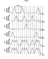
- FIGS. 2(1) through (6) show timing charts of the embodiment shown in FIG. 1.
- Optical signal sources 10-1 through 10-4 generate RZ optical signals of 10 Gb/s having different wavelengths ⁇ 1 through ⁇ 4 according to data signals 12-1 through 12-4 of 10 Gb/s, respectively.
- the optical pulse width is better as narrow as possible, it is applicable as far as it fits in a time slot of 40 Gb/s after time-division-multiplexing.
- Optical delay devices 14-1 through 14-4 delay the optical signals output from the respective optical signal sources 10-1 through 10-4 so as to enter predetermined different time slots of 40 Gb/s respectively.
- FIGS. 2(1) through (4) show waveform examples of the optical signals output from the optical delay devices 14-1 through 14-4.
- each delay time of the optical delay devices 14-1 through 14-4 is set so that the output light from the optical delay device 14-1 enters a first time slot, the output light from the optical delay device 14-2 enters a second time slot, the output light from the optical delay device 14-3 enters a third time slot, and the output light from the optical delay device 14-4 enters a fourth time slot in the four time slots obtained when 40 Gb/s is divided into four 10 Gb/s in the time domain.
- an electric delay device having the similar function can be disposed on each input side of the optical signal sources 10-1 through 10-4.
- An optical multiplexer 16 multiplexes the respective optical signal output from the optical delay devices 14-1 through 14-4 in the wavelength domain.
- FIG. 2(5) shows an example of optical intensity waveform of the output light from the optical multiplexer 16. When two optical pulses exist on adjacent time slots, they are combined together and form a single pulse with a slightly depressed peak. Such combination of optical pulses does not interfere with this embodiment.
- An optical amplifier 18 amplifies the output light from the optical multiplexer 16 and applies it to a wavelength converter 20.
- the wavelength converter 20 is a device to convert a wavelength of the input light into a wavelength ⁇ 5, namely to generate light of the wavelength ⁇ 5 having an essentially identical waveform (or a reverse waveform) to that of the input light.
- the wavelength of the input light and the wavelength ⁇ 5 after the conversion can be the same, desirably they should be different to avoid the interference. Even if the input light contains light having a plurality of wavelengths, the wavelength converter 20 outputs the light of the wavelength ⁇ 5 having a waveform according to that of the combined light intensity.
- the details of the wavelength converter 20 are disclosed in Japanese Laid-Open Patent Publication No. 10-78595 and U.S. Patent 5,959,764 to correspond to the Japanese Laid-Open patent Publication, for instance. Accordingly, on the details of the wavelength converter 20, those references will be cited.
- the output light from the optical amplifier 18 enters a port A of an optical circulator 22 and outputs from a port B to enter a waveguide transmission type InGaAsP electroabsorption optical modulator 24.
- a CW light source 26 generates CW laser light (probe light) of the wavelength ⁇ 5.
- the CW laser light output from the CW optical source 26 enters the optical modulator 24 so as to propagate in the opposite direction to the input light from the port B of the optical circulator 22.
- a DC power supply 28 applies DC voltage, e.g. DC 3V, to the optical modulator 24.
- an electric cooling unit is disposed to stabilize the temperature of the optical modulator 24.
- the light (the output light from the multiplexer 16) from the port B of the optical circulator 22 and the output light from the CW light source 26 interact with each other in the optical modulator 24, and consequently the optical intensity waveform of the light having the wavelength ⁇ 5 which is output toward the port B of the optical circulator 22 from the optical modulator 24 represents a copy of the optical intensity waveform of the output light from the multiplexer 16 as shown in FIG. 2(6).
- the optical circulator 22 transmits the light that entered the port B from the optical modulator 24 to a port C and applies it to an optical bandpass filter 30 from the port C.
- the bandpass filter 30 is set to exclusively transmit the wavelength ⁇ 5 alone. Unnecessary wavelength components such as components of the wavelengths ⁇ 1 through ⁇ 4 are removed by the optical bandpass filter 30.
- the output of the optical bandpass filter 30 is signal light of 40 Gb/s in which the four data 12-1 through 12-4 of 10 Gb/s are time-division-multiplexed.
- the embodiment shown in FIG. 1 is also applicable to a device to convert an optical WDM signal into an optical TDM signal.
- timings between optical signals of respective wavelengths entered the optical delay device 14-1 through 14-4 is measured, and the delay time of each of the optical delay devices 14-1 through 14-4 is automatically controlled so that the optical signals are located on different time slots after the TDM respectively.
- the delay time of each of the optical delay devices 14-1 through 14-4 can be preset.
- FIG. 3 shows a schematic block diagram of an embodiment to convert an optical WDM signal from an optical transmission line into an optical TDM signal. Elements identical to those in FIG. 1 are labeled with common reference numerals.
- An optical WDM signal 31 composed of optical signals of 10 Gb/s having wavelengths ⁇ 1 through ⁇ 4 enters a demultiplexer 32 from an optical fiber transmission line.
- the demultiplexer 32 demultiplexes the optical WDM signal 31 into individual optical signals having the wavelengths ⁇ 1 through ⁇ 4 and applies them to optical receivers 34-1 through 34-4 respectively.
- the optical receivers 34-1 through 34-4 convert the input optical signals into electric signals and apply them to optical transmitters 36-1 through 36-4 respectively.
- the optical transmitters 36-1 through 36-4 convert the optical signals from the optical receivers 34-1 through 34-4 into optical signals of RZ optical pulse having wavelengths ⁇ 1 through ⁇ 4 and apply them to optical delay devices 38-1 through 38-4 respectively.
- the optical receivers 34-1 through 34-4 also extract a clock component from the input signal light.
- the clocks extracted by the optical receivers 34-1 through 34-3 are applied to phase comparators 39-1 through 39-3 while the clocks extracted by the optical receiver 34-4 are applied to the optical delay device 38-4 and the phase comparators 39-1 through 39-3 as a reference clock.
- Each of the phase comparators 39-1 through 39-3 compares phase of the clock (the reference clock) from the optical receiver 34-4 to the clocks from the associated one of the optical receivers 34-1 through 34-3 and controls the delay time of the associated one of the optical delay devices 38-1 through 38-3 so that optical signals to be output from the optical transmitters 36-1 through 36-3 are respectively located on a first time slot, a second time slot and a third time slot after the time-division-multiplexing.
- the delay time of the optical delay device 38-4 is controlled according to the reference clock from the optical receiver 34-4 so that the signal light output from the optical transmitter 36-4 is located on a fourth time slot after the time-division-multiplexing.
- the optical signals output from the optical delay devices 38-1 through 38-4 are located at timings shown in FIGS. 2(1) through (4).
- the operation after this is the same with the explanation of the embodiment in FIG. 1 and thus TDM signal light at 40 Gb/s is finally obtained.
- the optical receiver 34-1 through 34-4 and the optical transmitter 36-1 through 36-4 function as a device to shape a waveform of the signal light as a whole.
- the optical transmitter 36-1 through 36-4 can output an optical signal having a wavelength different from that of an optical signal to enter the optical receiver 34-1 through 34-4.
- the optical receiver 34-1 through 34-4 and the optical transmitter 36-1 through 36-4 function as a wavelength converter as a whole.
- photodetectors and clock extracting circuits to extract a clock of the signal light having each wavelength should be disposed instead of the optical receiver 34-1 through 34-4 and the optical transmitter 36-1 through 36-4.
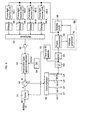
- FIG. 4 shows a schematic block diagram of an embodiment of a TDM demultiplexer according to the invention.
- the embodiment shown in FIG. 4 demultiplexes a signal of 40 Gb/s into respective four signals of 10 Gb/s.
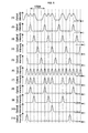
- FIGS. 5(1) through (11) each shows an optical waveform of each part in the embodiment shown in FIG. 4.
- FIG. 5(1) shows a waveform example of the input signal light 40.
- Pulse light sources 46-1 through 46-4 to generate pulse light of 10 Gb/s after the TDM demultiplexing are provided as many as the number of the signals after the TDM demultiplexing and laser-oscillate at wavelengths ⁇ 1 through ⁇ 4, which are different from each other, respectively.
- the optical pulses output from the pulse light sources 46-1 through 46-4 are temporally adjusted in the time domain by the optical delay devices 48-1 through 48-4 respectively and applied to a multiplexer 50. Each delay time of the optical delay devices 48-1 through 48-4 is adjusted so that each optical pulse output from the pulse light sources 46-1 through 46-4 is disposed on a different time slot from the other when 40 Gb/s is divided into four time slots of 10 Gb/s.
- FIG. 5(1) through (4) show waveform examples of the output light from the optical delay devices 48-1 through 48-4 respectively.
- the multiplexer 50 multiplexes the output light from the optical delay devices 48-1 through 48-4 in the wavelength domain.
- FIG. 5(6) shows a waveform example of the output light from the multiplexer 50.
- the output light from the multiplexer 50 is composed of pulse light of 40 Gb/s although the optical signals having the four wavelengths are periodically mixed.
- the output light from the multiplexer 50 is amplified by an optical amplifier 52 and applied to the optical modulator 44 as probe light in the opposite transmission direction to the 40 Gb/s signal light.
- a DC power source 54 applies a constant DC voltage to the optical modulator 44.
- the optical modulator 44 functions as a wavelength converter to input pulse light as probe light.
- the optical modulator 44 more specifically, functions as an optical AND circuit to perform an AND-operation between the input 40 Gb/s signal light 40 and the pulse train output from the optical amplifier 52 or as an optical gate circuit to selectively transmit an optical pulse included in the optical pulse train from the optical amplifier 52 according to the input signal light 40 of 40 Gb/s as a window.
- FIG. 5(7) shows a waveform of the light which output from the optical amplifier 53 and transmitted through the optical modulator 44.
- Such operation of the optical modulator 44 is described in detail with reference to FIGS. 6 through 8 in Japanese Laid-Open Patent Publication No. 10(1998)-78595 and U.S. Patent No. 5,959,764.
- the optical pulses of wavelengths ⁇ 1 through ⁇ 4 output from the optical modulator 44 are applied to the port B of the optical circulator 42, transmitted to a port C and sent to a wavelength demultiplexer 56 from the port C.
- the wavelength demultiplexer 56 demultiplexes the light from the port C of the optical circulator 42 into different wavelengths and outputs them. Accordingly, the wavelength demultiplexer 56 outputs 10 Gb/s optical signals 58-1 through 58-4 having the wavelengths ⁇ 1 through ⁇ 4 being different from each other.
- FIGS. 5(8) through (11) show waveform examples of the signal light 58-1 through 58-4 respectively.
- a photodetector 60 converts the optical signal 58-4 having the wavelength ⁇ 4 into an electric signal.
- a bandpass filter 62 extracts a clock component of 10 Gb/s out of the output from the photodetector 60 and applies it to a PLL circuit 64.
- the PLL circuit 64 of a well-known configuration generates a 10 GHz clock signal synchronized with the output from the BPF 62.
- the PLL circuit 64 is composed of, for example, a 10 GHz voltage control oscillator (VCO) 66, a comparator 68 to compare phase between the output from the BPF 62 and that from the VCO 66 and to output an error signal indicating a phase error and a voltage generator 70 to generate a voltage signal to control a oscillation frequency of the VCO 66 according to the error signal output from the comparator 68.
- VCO voltage control oscillator
- the 10 GHz clock generated by the PLL circuit 64 is applied to the pulse light sources 46-1 through 46-4.
- the pulse light sources 46-1 through 46-4 generate pulse light having a frequency equal to that of the clock from the PLL circuit 64.
- the pulse light sources 46-1 through 46-4 can be composed of either a mode locked laser to generate pulse light according to the clock from the PLL circuit 64 or a combination of a CW laser and an electroabsorption optical modulator to generate pulse light by modulating intensity of output light from the CW laser according to the clock from the PLL circuit 64.
- the pulse light sources 46-1 through 46-4 generate pulse light synchronized with the input signal light 40.
- the bit rate of the optical pulse output from each of the pulse light sources 46-1 through 46-4 is one fourth of the input signal light.
- a time slot ID detector 72 detects information to identify a time slot, namely time slot ID, out of the output signal from the photodetector 60.
- the time slot ID for example, is the information to show on which time slot after the TDM each signal to be multiplexed in the time domain is disposed and can be the destination of the signal. With this operation, it is determined to which time slot on the input signal light 40 the signal 58-4 should be disposed currently.
- the time slot ID detector 72 adjusts the delay time of the optical delay devices 48-1 through 48-4 according to the detected result so that the optical signals 58-1 through 58-4 are disposed to the first time slot, the second time slot, the third time slot and the forth time slot on the input 40 Gb/s signal light 40 respectively.
- the delay time of the optical delay devices 46-1 through 46-4 should be any one of 0, 25 ps, 50 ps and 75 ps, and the time slot ID detector 72 assigns those time to the respective optical delay devices 48-1 through 48-4 as delay time.
- each delay time of the optical delay devices 48-1 through 48-4 is different from the others.
- the demultiplexing of the wavelength by the demultiplexer 56 is unnecessary, and the output light from the port C of the optical circulator 42 is applied to the optical fiber instead.
- an optical filter is necessary to extract the signal light having the wavelength ⁇ 4 and to apply it to the photodetector 60.
- the embodiment shown in FIG. 4 also functions as a converter to convert an optical TDM signal into an optical WDM signal.
- the optical delay devices 48-1 through 48-4 control the cross timing between the output optical pulses from the pulse light sources 46-1 through 46-4 in the time domain.
- the optical pulse phase of the input signal light 40 is controlled according to the detected result of the time slot ID detector 72 while the cross delay time of the optical delay devices 48-1 through 48-4 is fixed.
- FIG. 6 shows a schematic block diagram of such modified embodiment. Elements common to those in FIG. 4 are numbered with the same reference numerals. However, the delay time of the optical delay devices 48-1 through 48-4 are generally fixed to 0, 25 ps, 50 ps and 50 ps respectively when uneven response delay of the pulse light sources 46-1 through 46-4 is disregarded.
- the input signal light 40 enters the port A of the optical circulator 42 via an optical delay device 74 having valuable delay time.
- the delay time of the optical delay devices 48-1 through 48-4 are adjusted and fixed in advance.
- the delay time of any one of the optical delay devices for example the optical delay device 48-1, can be zero. That is, the optical delay device 48-1 can be omitted.
- the time slot ID detector 72 adjusts the delay time of the optical delay device 74 according to the detected result so that the signal light 58-4 carries a signal on the fourth time slot. Consequently, the timings between the input signal light 40 and the output pulse light from the optical amplifier 52 are controlled so that the signal light 58-1 carries a signal on the first time slot on the input signal light 40, the signal light 58-2 carries a signal on the second time slot, the signal light 58-3 carries a signal on the third time slot, and the signal light 58-4 carries the signal light on the fourth slot.
- FIG. 4 shows a schematic block diagram of such modified embodiment. Elements common to those in FIG. 4 are numbered with the same reference numerals.
- the demultiplexer 76 divides the input signal light 40 of a 40 Gb/s TDM signal into two portions and applies one portion to the port A of the optical circulator 42 and the other to a photodetector 78.
- the photodetector 78 converts the input light into an electric signal.
- a bandpass filter 80 extracts a 40 GHz component from the output from the photodetector 78 and applies it to a 1/4 frequency divider 82.
- the frequency divider 82 generates a 10 GHz signal synchronized with the output from the BPF 80.
- the frequency divider 82 is composed of a 10 GHz voltage control oscillation (VCO) 84, a quadrupler 86 to quadruple output frequency of the VCO 84, a comparator 88 to compare phase between the output from the BPF 80 and that of the quadrupler 86 and to outputs a error signal indicating a phase error, and a voltage generator 90 to generate a voltage signal to control the oscillation frequency of the VCO 84 according to the error signal output from the comparator 88.
- VCO voltage control oscillation
- the 10 GHz clock output from the VCO 84 of the frequency divider 82 is applied to the pulse light sources 46-1 through 46-4.
- the pulse light sources 46-1 through 46-4 generate pulse light having the same frequency with the clock from the frequency divider 82.
- the operation after this is identical to the description of the embodiment shown in FIG. 4.
- a signal of 40 Gb/s is demultiplexed into four signals of 10 Gb/s. Since the optical pulse width of the pulse light sources 46-1 through 46-4 is not necessarily as narrow as that of the conventional art, it can be realized with low costs. By increasing the number of the pulse light sources 46-1 through 46-4, an optical TDM signal at even higher speed can be demultiplexed into a plurality of signals in the time domain.
- a plurality of signals can be multiplexed in the time domain with a simple configuration.
- a signal at a high speed can be demultiplexed into a plurality of signals at a low speed in the time domain.
Landscapes
- Engineering & Computer Science (AREA)
- Computer Networks & Wireless Communication (AREA)
- Signal Processing (AREA)
- Optical Communication System (AREA)
- Optical Modulation, Optical Deflection, Nonlinear Optics, Optical Demodulation, Optical Logic Elements (AREA)
- Time-Division Multiplex Systems (AREA)
Applications Claiming Priority (2)
| Application Number | Priority Date | Filing Date | Title |
|---|---|---|---|
| JP2000083997 | 2000-03-24 | ||
| JP2000083997A JP2001274772A (ja) | 2000-03-24 | 2000-03-24 | Tdm光多重装置、tdm光分離装置、wdm/tdm変換装置及びtdm/wdm変換装置 |
Publications (2)
| Publication Number | Publication Date |
|---|---|
| EP1137213A2 true EP1137213A2 (fr) | 2001-09-26 |
| EP1137213A3 EP1137213A3 (fr) | 2002-12-18 |
Family
ID=18600540
Family Applications (1)
| Application Number | Title | Priority Date | Filing Date |
|---|---|---|---|
| EP01107260A Withdrawn EP1137213A3 (fr) | 2000-03-24 | 2001-03-23 | Multiplexeur optique de TDM, démultiplexeur optique de TDM , convertisseur WDM/TDM et convertisseur TDM/WDM |
Country Status (3)
| Country | Link |
|---|---|
| US (1) | US6775478B2 (fr) |
| EP (1) | EP1137213A3 (fr) |
| JP (1) | JP2001274772A (fr) |
Cited By (9)
| Publication number | Priority date | Publication date | Assignee | Title |
|---|---|---|---|---|
| FR2838836A1 (fr) * | 2002-04-19 | 2003-10-24 | France Telecom | Dispositif optique et procede pour convertir des signaux wdm en un signal otdm, et reciproquement |
| EP1365532A1 (fr) * | 2002-05-22 | 2003-11-26 | Lucent Technologies Inc. | Multiplexeur optique à capacité de traitement de canaux multiples simultanés et convertisseur OTDM-WDM |
| WO2005076508A1 (fr) * | 2004-01-06 | 2005-08-18 | France Telecom | Dispositif de sous-echantillonnage temporel d'un signal optique de type otdm, convertisseur otdm-wdm comportant un tel dispositif et convertisseur wdm-otdm |
| US7027735B2 (en) | 2002-04-03 | 2006-04-11 | Corning Incorporated | Unequal pulse spacer |
| WO2006091351A1 (fr) * | 2005-02-22 | 2006-08-31 | Northrop Grumman Corporation | Interrogation en multiplexage par repartition dans le temps matriciel |
| EP1909412A1 (fr) * | 2006-10-06 | 2008-04-09 | Acterna, LLC | Test de liens optiquement amplifiés à l'aide de signaux de test de multiplexage temporel |
| RU2456547C1 (ru) * | 2011-03-18 | 2012-07-20 | Российская Федерация, от имени которой выступает Государственная корпорация по атомной энергии "Росатом" (Госкорпорация "Росатом") | Многоканальная волоконно-оптическая система для синхронного запуска регистраторов |
| EP2725725A1 (fr) * | 2012-10-26 | 2014-04-30 | Fujitsu Limited | Système de transmission optique et procédé de commande |
| WO2025244728A1 (fr) * | 2024-05-20 | 2025-11-27 | Microsoft Technology Licensing, Llc | Liaison optique temporellement multiplexée avec retard |
Families Citing this family (30)
| Publication number | Priority date | Publication date | Assignee | Title |
|---|---|---|---|---|
| JP3784771B2 (ja) * | 2001-03-16 | 2006-06-14 | ローク マナー リサーチ リミテッド | 光データ圧縮装置及び方法 |
| WO2002100021A2 (fr) * | 2001-06-01 | 2002-12-12 | Fujitsu Network Communications, Inc. | Systeme et procede de multiplexage de donnees mrt et de paquets de donnees |
| US7068936B2 (en) * | 2002-06-03 | 2006-06-27 | Agere Systems Inc. | Methods and apparatus for optical switching |
| US20040057734A1 (en) * | 2002-09-25 | 2004-03-25 | Lucent Technologies, Inc. | Method and system for reducing transmission penalties associated with ghost pulses |
| US7519085B2 (en) * | 2002-10-18 | 2009-04-14 | Temic Automotive Of North America, Inc. | Control unit for transmitting audio signals over an optical network and methods of doing the same |
| US7218859B2 (en) * | 2003-04-11 | 2007-05-15 | Lucent Technologies Inc. | System and method for an optical signal monitor |
| JP4495415B2 (ja) * | 2003-06-26 | 2010-07-07 | 独立行政法人科学技術振興機構 | Otdm伝送方法及び装置 |
| JP3762997B2 (ja) * | 2003-08-28 | 2006-04-05 | 独立行政法人情報通信研究機構 | 光パルス分離装置及び方法 |
| JP4552610B2 (ja) * | 2003-11-18 | 2010-09-29 | 住友電気工業株式会社 | 波長変換装置 |
| JP4574187B2 (ja) * | 2004-02-20 | 2010-11-04 | 富士通株式会社 | 光同期装置 |
| ITMI20042312A1 (it) * | 2004-12-01 | 2005-03-01 | Marconi Comm Spa | Multiplexer con add-drop ottico |
| FR2884086A1 (fr) * | 2005-04-05 | 2006-10-06 | France Telecom | Transmission optique entre une premiere unite et une pluralite de secondes unites connectees entre elles au moyen d'un reseau d'acces optique passif |
| JP4682692B2 (ja) * | 2005-05-16 | 2011-05-11 | 沖電気工業株式会社 | 光通信システム |
| GB2446528B (en) * | 2005-09-27 | 2010-11-24 | Fujitsu Ltd | Optical signal multiplexing device and optical signal multiplexing method |
| US7623798B1 (en) * | 2005-10-04 | 2009-11-24 | Sprint Communications Company L.P. | Polarization mode dispersion mitigation of multiple optical communication channels |
| US7941053B2 (en) * | 2006-10-19 | 2011-05-10 | Emcore Corporation | Optical transceiver for 40 gigabit/second transmission |
| US7970281B2 (en) * | 2007-01-26 | 2011-06-28 | Fujitsu Limited | System and method for managing different transmission architectures in a passive optical network |
| JP5034790B2 (ja) * | 2007-08-31 | 2012-09-26 | 富士ゼロックス株式会社 | データ処理システム |
| US7769062B2 (en) * | 2008-03-20 | 2010-08-03 | National Research Council Of Canada | Quantum dot based semiconductor waveguide devices |
| WO2010053911A2 (fr) | 2008-11-04 | 2010-05-14 | Massachusetts Institute Of Technology | Combinaison de faisceaux à longueurs d'onde multiples monodimensionnelle à cavité externe de deux éléments lasers bidimensionnels |
| JP2010199657A (ja) * | 2009-02-23 | 2010-09-09 | Oki Electric Ind Co Ltd | 時分割多重符号化送信信号生成方法及び時分割多重符号化送信信号生成装置 |
| WO2010125657A1 (fr) * | 2009-04-28 | 2010-11-04 | 富士通株式会社 | Dispositif de traitement de signaux optiques |
| US8614853B2 (en) | 2010-03-09 | 2013-12-24 | Massachusetts Institute Of Technology | Two-dimensional wavelength-beam-combining of lasers using first-order grating stack |
| US8531761B2 (en) * | 2010-05-27 | 2013-09-10 | Massachusetts Institute Of Technology | High peak power optical amplifier |
| US9620928B2 (en) | 2010-07-16 | 2017-04-11 | Massachusetts Institute Of Technology | Continuous wave or ultrafast lasers |
| JP2013168500A (ja) | 2012-02-15 | 2013-08-29 | Mitsubishi Electric Corp | 光半導体装置 |
| US8953942B1 (en) * | 2012-04-27 | 2015-02-10 | Google Inc. | Hybrid WDM-TDM passive optical network |
| US10181942B2 (en) * | 2015-03-16 | 2019-01-15 | Mitsubishi Electric Corporation | Optical communication system, optical signal generation device, and optical signal reception device |
| US9976919B2 (en) | 2015-03-27 | 2018-05-22 | Kettering University | Fiber-optic sensor assembly |
| DE102017206347B4 (de) * | 2017-04-12 | 2019-07-04 | Deutsches Zentrum für Luft- und Raumfahrt e.V. | Sender für ein optisches Freistrahl-Kommunikationssystem sowie optisches Freistrahl-Kommunikationssystem |
Family Cites Families (10)
| Publication number | Priority date | Publication date | Assignee | Title |
|---|---|---|---|---|
| DE3853935T2 (de) * | 1987-09-30 | 1995-10-12 | Nippon Electric Co | Zeit- und Wellenlängenmultiplex-Vermittlungssystem. |
| FR2672173B1 (fr) * | 1991-01-29 | 1993-09-03 | Cit Alcatel | Multiplexeur temporel photonique, et demultiplexeur temporel photonique. |
| JP3201564B2 (ja) * | 1994-12-06 | 2001-08-20 | 日本電信電話株式会社 | 光多重化回路 |
| JP3201566B2 (ja) | 1995-01-17 | 2001-08-20 | 日本電信電話株式会社 | 光多重分離回路 |
| FR2736777B1 (fr) * | 1995-07-12 | 1997-08-08 | Alcatel Nv | Reseau de transmission optique avec multiplexage de longueurs d'onde |
| JP3458613B2 (ja) * | 1996-09-04 | 2003-10-20 | Kddi株式会社 | 波長変換装置及び光演算装置 |
| FR2754409B1 (fr) * | 1996-10-07 | 1998-11-13 | Alsthom Cge Alcatel | Dispositif a retard variable pour signaux optiques |
| FR2762732B1 (fr) | 1997-04-28 | 1999-06-04 | Alsthom Cge Alcatel | Procede et dispositif de decompression d'impulsions constituant un signal optique binaire |
| JP3438770B2 (ja) * | 1998-03-06 | 2003-08-18 | Kddi株式会社 | 光ディジタル再生装置 |
| JP4454763B2 (ja) * | 2000-03-03 | 2010-04-21 | 富士通株式会社 | 信号光を波形整形するための方法、装置及びシステム |
-
2000
- 2000-03-24 JP JP2000083997A patent/JP2001274772A/ja not_active Withdrawn
-
2001
- 2001-03-23 US US09/816,630 patent/US6775478B2/en not_active Expired - Fee Related
- 2001-03-23 EP EP01107260A patent/EP1137213A3/fr not_active Withdrawn
Cited By (16)
| Publication number | Priority date | Publication date | Assignee | Title |
|---|---|---|---|---|
| US7027735B2 (en) | 2002-04-03 | 2006-04-11 | Corning Incorporated | Unequal pulse spacer |
| US7577363B2 (en) | 2002-04-19 | 2009-08-18 | Erwan Pincemin | Optical device and method of converting WDM signals into an OTDM signal and vice versa |
| WO2003090392A1 (fr) * | 2002-04-19 | 2003-10-30 | France Telecom | Dispositif optique et procédé pour convertir des signaux wdm en un signal otdm, et réciproquement |
| US7844180B2 (en) | 2002-04-19 | 2010-11-30 | Erwan Pincemin | Optical device and a method for converting WDM signals into an OTDM signal and vice versa |
| FR2838836A1 (fr) * | 2002-04-19 | 2003-10-24 | France Telecom | Dispositif optique et procede pour convertir des signaux wdm en un signal otdm, et reciproquement |
| EP1365532A1 (fr) * | 2002-05-22 | 2003-11-26 | Lucent Technologies Inc. | Multiplexeur optique à capacité de traitement de canaux multiples simultanés et convertisseur OTDM-WDM |
| US7885544B2 (en) | 2004-01-06 | 2011-02-08 | France Telecom | Device for temporal subsampling of an OTDM optical signal, OTDM-WDM converter comprising same and OTDM-WDM converter |
| WO2005076508A1 (fr) * | 2004-01-06 | 2005-08-18 | France Telecom | Dispositif de sous-echantillonnage temporel d'un signal optique de type otdm, convertisseur otdm-wdm comportant un tel dispositif et convertisseur wdm-otdm |
| WO2006091351A1 (fr) * | 2005-02-22 | 2006-08-31 | Northrop Grumman Corporation | Interrogation en multiplexage par repartition dans le temps matriciel |
| US7403712B2 (en) | 2005-02-22 | 2008-07-22 | Northrop Grumman Corporation | Matrix time division multiplex (MTDM) interrogation |
| US7925158B2 (en) | 2006-10-06 | 2011-04-12 | Acterna Llc | Testing optically amplified links with time-division multiplexed test signals |
| EP1909412A1 (fr) * | 2006-10-06 | 2008-04-09 | Acterna, LLC | Test de liens optiquement amplifiés à l'aide de signaux de test de multiplexage temporel |
| RU2456547C1 (ru) * | 2011-03-18 | 2012-07-20 | Российская Федерация, от имени которой выступает Государственная корпорация по атомной энергии "Росатом" (Госкорпорация "Росатом") | Многоканальная волоконно-оптическая система для синхронного запуска регистраторов |
| EP2725725A1 (fr) * | 2012-10-26 | 2014-04-30 | Fujitsu Limited | Système de transmission optique et procédé de commande |
| US9020339B2 (en) | 2012-10-26 | 2015-04-28 | Fujitsu Limited | Optical transmission system and control method |
| WO2025244728A1 (fr) * | 2024-05-20 | 2025-11-27 | Microsoft Technology Licensing, Llc | Liaison optique temporellement multiplexée avec retard |
Also Published As
| Publication number | Publication date |
|---|---|
| EP1137213A3 (fr) | 2002-12-18 |
| US6775478B2 (en) | 2004-08-10 |
| JP2001274772A (ja) | 2001-10-05 |
| US20020126346A1 (en) | 2002-09-12 |
Similar Documents
| Publication | Publication Date | Title |
|---|---|---|
| US6775478B2 (en) | Optical TDM multiplexer, optical TDM demultiplexer, WDM/TDM converter and TDM/WDM converter | |
| US5805321A (en) | Control unit for optical modulators producing multiplexed optical output signal | |
| US5408349A (en) | Optical frequency division multiplexing transmission system | |
| US6594070B2 (en) | Optical communication system, optical receiver and wavelength converter | |
| US5894247A (en) | Optical PLL circuit and method of controlling the same | |
| US8090268B2 (en) | Long-distance synchronous transmission method using optical fiber | |
| JP3000551B2 (ja) | 光電式周波数分割器回路及びその操作方法 | |
| US6560007B2 (en) | Bit-phase synchronized optical pulse stream local generator | |
| US20050047791A1 (en) | Dispersion compensation control method and apparatus thereof and optical transmission method and system thereof | |
| JPH1063350A (ja) | 光周波数安定化装置 | |
| US7623792B2 (en) | Clock extracting method and apparatus thereof | |
| US6178022B1 (en) | Optical transmitter and optical receiver for optical time division multiplexing transmission | |
| JPH0767155A (ja) | 光システム | |
| JP2001268009A (ja) | 波長分割多重伝送システムのための再生器 | |
| JP2004064148A (ja) | 光時分割多重信号チャネル識別方法及びその装置 | |
| JP4405297B2 (ja) | Otdm時間チャネル分離、電気クロックリカバリ、および光クロック発生を同時的に行う装置、光クロックリカバリ装置 | |
| US7164862B1 (en) | Transmitting an optical signal with corresponding WDM and TDM channels | |
| US7027466B1 (en) | Multiplexer, demultiplexer and multiplex communication system | |
| JP2002281000A (ja) | Wdmシステムにおいて時間遅延を調整するための方法およびチャネルを同期させるための装置 | |
| JP2003258373A (ja) | 波長制御装置及び波長制御方法 | |
| JP3317025B2 (ja) | 光周波数分割多重伝送装置 | |
| JPH0983457A (ja) | 光多重信号分離回路 | |
| US20020122229A1 (en) | All-optical high bit-rate multiplexer | |
| US20050175348A1 (en) | Synchronizer for rz-wdm signals and method for synchronization | |
| JPH09102776A (ja) | 光クロック信号抽出回路 |
Legal Events
| Date | Code | Title | Description |
|---|---|---|---|
| PUAI | Public reference made under article 153(3) epc to a published international application that has entered the european phase |
Free format text: ORIGINAL CODE: 0009012 |
|
| AK | Designated contracting states |
Kind code of ref document: A2 Designated state(s): AT BE CH CY DE DK ES FI FR GB GR IE IT LI LU MC NL PT SE TR |
|
| AX | Request for extension of the european patent |
Free format text: AL;LT;LV;MK;RO;SI |
|
| PUAL | Search report despatched |
Free format text: ORIGINAL CODE: 0009013 |
|
| AK | Designated contracting states |
Kind code of ref document: A3 Designated state(s): AT BE CH CY DE DK ES FI FR GB GR IE IT LI LU MC NL PT SE TR |
|
| AX | Request for extension of the european patent |
Free format text: AL;LT;LV;MK;RO;SI |
|
| 17P | Request for examination filed |
Effective date: 20030203 |
|
| AKX | Designation fees paid |
Designated state(s): FR |
|
| REG | Reference to a national code |
Ref country code: DE Ref legal event code: 8566 |
|
| STAA | Information on the status of an ep patent application or granted ep patent |
Free format text: STATUS: THE APPLICATION HAS BEEN WITHDRAWN |
|
| 18W | Application withdrawn |
Effective date: 20050113 |