EP1137337B1 - Hilfsmittel zum fischen - Google Patents
Hilfsmittel zum fischen Download PDFInfo
- Publication number
- EP1137337B1 EP1137337B1 EP99962296A EP99962296A EP1137337B1 EP 1137337 B1 EP1137337 B1 EP 1137337B1 EP 99962296 A EP99962296 A EP 99962296A EP 99962296 A EP99962296 A EP 99962296A EP 1137337 B1 EP1137337 B1 EP 1137337B1
- Authority
- EP
- European Patent Office
- Prior art keywords
- fishing
- aid according
- fishing aid
- line
- holder
- Prior art date
- Legal status (The legal status is an assumption and is not a legal conclusion. Google has not performed a legal analysis and makes no representation as to the accuracy of the status listed.)
- Expired - Lifetime
Links
- 239000003381 stabilizer Substances 0.000 claims description 5
- 239000011324 bead Substances 0.000 description 3
- 230000000717 retained effect Effects 0.000 description 3
- 238000007796 conventional method Methods 0.000 description 2
- 238000004519 manufacturing process Methods 0.000 description 2
- 239000000853 adhesive Substances 0.000 description 1
- 230000001070 adhesive effect Effects 0.000 description 1
- 239000002390 adhesive tape Substances 0.000 description 1
- 230000006835 compression Effects 0.000 description 1
- 238000007906 compression Methods 0.000 description 1
- 238000010276 construction Methods 0.000 description 1
- 239000002184 metal Substances 0.000 description 1
- 238000012986 modification Methods 0.000 description 1
- 230000004048 modification Effects 0.000 description 1
Images

Classifications
-
- A—HUMAN NECESSITIES
- A01—AGRICULTURE; FORESTRY; ANIMAL HUSBANDRY; HUNTING; TRAPPING; FISHING
- A01K—ANIMAL HUSBANDRY; AVICULTURE; APICULTURE; PISCICULTURE; FISHING; REARING OR BREEDING ANIMALS, NOT OTHERWISE PROVIDED FOR; NEW BREEDS OF ANIMALS
- A01K91/00—Lines
- A01K91/03—Connecting devices
- A01K91/047—Connecting devices for connecting lines to lines
-
- A—HUMAN NECESSITIES
- A01—AGRICULTURE; FORESTRY; ANIMAL HUSBANDRY; HUNTING; TRAPPING; FISHING
- A01K—ANIMAL HUSBANDRY; AVICULTURE; APICULTURE; PISCICULTURE; FISHING; REARING OR BREEDING ANIMALS, NOT OTHERWISE PROVIDED FOR; NEW BREEDS OF ANIMALS
- A01K97/00—Accessories for angling
Definitions
- the present invention relates to a fishing aid, and more particularly to a fishing aid which assists in making a rig or other fishing tackle.
- Rigs are commonly used in most types of fishing and generally consist of one or more hooks attached to a fishing line using a swivel (or similar component). The swivel is held in place using a crimp (or similar device) and a bead on each side of the swivel.
- rigs are made by hand, typically by extending lengths of fishing line from a spool, slipping the various components onto the line and keeping the components in place on the line by the use of crimps (or similar devices), or by tying the line in appropriate places.
- This conventional method is very time consuming and is often difficult to assemble as one hand is required to keep tension in the fishing line whilst the other hand feeds the components onto the line and assembles them.
- US-A-2518687 discloses a machine for forming leaders according to the preamble of claim 1.
- a fishing aid comprising a body, at least one spool holder coupled to the body, and a retainer coupled to the body to receive a line, characterised in that the length of the body is adjustable.
- the body is typically substantially U-shaped.
- the body comprises a first portion and a second portion, the first and second portions being telescopically coupled so that the length of the body may be adjusted.
- the fishing aid may optionally be provided with indicia, typically to indicate the length of component parts of a fishing rig or trace, or to indicate the length of line which has been extended (eg the length of a fishing rig, snood or the like), or to indicate the length to which the body has been adjusted.
- indicia typically to indicate the length of component parts of a fishing rig or trace, or to indicate the length of line which has been extended (eg the length of a fishing rig, snood or the like), or to indicate the length to which the body has been adjusted.
- the spool holder is typically located on one of the arms of the U-shaped body.
- a spool holder may be positioned on each arm of the U-shaped body.
- the spool holder typically includes a rod. The rod is typically removably coupled to the body.
- the retainer typically comprises a spring means such as a coil spring, compression spring, leaf spring etc, and in a preferred embodiment comprises at least one retaining spring.
- the retaining spring is typically positioned perpendicular to the body.
- the retaining spring can typically receive at least a portion of a fishing line between adjacent coils of the spring.
- the retaining spring is typically supported by a holder, the holder being optionally movably attached to the body.
- the holder is typically substantially U-shaped, the retaining spring being mounted between the arms of the U-shape.
- the holder is typically attached to the body substantially perpendicularly thereto.
- the holder is optionally provided with resilient stabilisers to enhance the stability of the aid.
- the fishing aid may includes a tension spring coupled to the or each arm of the U-shaped body.
- the fishing aid may also include a stopper, the stopper being provided on at least one of the arms of the body.
- the stopper is typically provided with a groove in which a fishing line may be positioned.
- the fishing aid optionally includes at least one hook positioned on the body. Two hooks are typically provided on the body, the or each hook typically being attached to the arms of the U-shaped body.
- the body is typically provided with at least one resilient stabiliser, the resilient stabiliser typically comprising a rubber foot.
- the line is typically a fishing line.
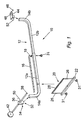
- the aid 10 includes a substantially U-shaped body 12, the body 12 comprising a first portion 12a and a second portion 12b.
- the first and second portions 12a, 12b are substantially L-shaped, the smaller sides of the L-shape forming two spaced apart arms 14a, 14b.
- the first and second portions 12a, 12b are telescopically coupled so that the distance between the arms 14a, 14b may be adjusted. This allows different lengths of rigs 11 to be made.
- the longer side of the L-shapes may include indicia (such as an adhesive tape measure 16) the indicia being used to measure the lengths of the component parts of the rig 11 or snoods 64.
- the indicia may optionally be used to indicate the distance between the arms 14a, 14b.
- the indicia allows a user to more accurately measure the length of the component parts of the rig 11 or snood 64 and/or set the distance between the arms 14a, 14b to correspond to the length of rig 11 which is required.
- the position of the first and second portions 12a, 12b may be fixed relative to one another using a tension screw 18.
- the tension screw 18 is threadedly engaged in an aperture 18a in the first portion 12a, one end of the screw 18 abutting against the second portion 12b to restrict movement of the portions 12a, 12b relative to one another.
- a spring holder 20 is coupled (optionally movably coupled) to the body 12.
- the spring holder 20 includes a cross-bar 22 which is attached to the body 20 using a retaining screw 24, or the like.
- At either end of the cross-bar 22 is an arm 26.
- a retaining spring 28 which is used to receive at least a portion of a fishing line 30 when the aid 10 is being stored, or when it is in use (ie to hold at least a portion of the rig 11 in a convenient location or to receive loose ends of the fishing line 30 during use of the aid 10).
- a rubber foot 31 may be provided on each end of the cross-bar 22 to enhance stability of the aid 10.
- One or more additional rubber feet 31 may also be provided on the body 12 to further enhance the stability of the aid 10.
- the spring holder 20 may be positioned at any convenient location on body 12 and secured in place using retaining screw 24.
- a spool holder 32 which is attached using a retaining screw 34 or the like.
- the holder 32 includes a base 36 which has an aperture (not shown) at the lower end thereof for receiving an upper end of arm 14a.
- a rod 38 is inserted through the base 36, and the holder 32 is positioned so that the rod 38 is substantially perpendicular to the body 12.
- a spool 40 (or a plurality thereof) which holds the fishing line 30 is positioned on the rod 38 and held in place on rod 38 using one or more rubber spool stops 42 (Fig. 1).
- a number of spools 40 containing fishing line of different breaking strengths are provided on the rod 38.
- a line hook 50 is located on the base 36 of the spool holder 32. Additionally, or alternatively, a tension spring (not shown) may be attached to the spool holder 32 (eg having the tension spring coupled to line hook 50, or provided directly on the base 36 of the spool holder 32) to provide tension to the fishing line 30 during assembly of the rig 11.
- a tension spring (not shown) may be attached to the spool holder 32 (eg having the tension spring coupled to line hook 50, or provided directly on the base 36 of the spool holder 32) to provide tension to the fishing line 30 during assembly of the rig 11.
- a rubber line holder 44 is removably attached to arm 14b using a retaining screw 46 or the like.
- the rubber line holder 44 has a groove 48 therein, groove 48 being capable of receiving a fishing line, as will be described.
- a second line hook 52 is positioned on the rubber line holder 44.
- a retaining device eg a loop of metal or the like
- the rubber line holder or directly to the arm 14b, the retaining device being used to hold an impact lead during assembly of the rig 11, so that the rig 11 can be directly attached to the impact lead.
- the spool holder 32 may be mounted to arm 14b.
- a further spool holder 32 may be coupled to the arm 14b in place of the rubber line holder 44 to allow a greater number of spools 40 to be mounted to the aid 10.
- a plurality of spools 40 having fishing lines 30 of different breaking strengths may be mounted on the or each spool holder 32.
- the fishing line 30 is despooled to the required length (which may be measured using the adhesive measuring tape 16).
- the line 30 ie the first end of rig 11
- the line 30 can be attached to a tension spring (not shown) which is coupled to the arm 14b.
- the tension spring may be attached directly to a portion of the arm 14b, or it can be attached to a portion of the rubber line holder 44.
- the tension spring may also be attached to hook 52 on the rubber line holder 44.
- the line 30 is typically attached to the tension spring using a split link (not shown).
- the end of the rig 11 may be attached directly (eg it may be tied or otherwise affixed (for example using a split link)) to the hook 52 without use of a tensioning spring.
- a tension spring is not used, the rig 11 will generally require to be tensioned by adjusting the distance between the arms 14a, 14b using the tension screw 18 and telescopic movement of the portions 12a, 12b.
- the end of the fishing line 30 may be extended from the spool 40 and positioned in the groove 48 on the rubber line holder 44. This provides a further anchor point for the line 30 during assembly of the rig 11.
- a first crimp 54, a first bead 56, a swivel 58, a second bead 60 and a second crimp 62 are threaded onto the fishing line 30 at a first location 68. This is then repeated at a second location 70 spaced apart from the first location 68. It should be noted that a plurality of swivels 58 or the like may be provided at various locations along the length of the rig 11 as required.
- the line 30 is then cut at or near spool 40.
- the loose end of the line 30 from the spool 40 may be retained between adjacent coils of retaining spring 28 so that the retaining spring 28 grips the loose end of line 30.
- the loose end of the line 30 from the spool 40 may be retained in the retaining spring 28 for convenience.
- the line 30 can be anchored as described above and then cut to the required length.
- the second (loose) end of the line 30 may be temporarily retained in the retaining spring 28, for example to allow a user to collate all the required components which make up the rig 11. Once the components have been collected, the loose end of the line 30 is then removed from the retaining spring 28, and the components threaded onto line 30.
- the second end of rig 11 is thereafter anchored to arm 14b.
- the second end of rig 11 may be attached to a second tension spring (not shown) coupled to the arm 14a.
- the second tension spring may be directly attached to base 36 of the spool holder 32. It may also be attached to a portion of arm 14a, or it may be attached directly to line hook 50. It should be noted that the second end of the rig 11 may be directly attached to the line hook 50 without the use of a second tension spring. As before, if a tension spring is not used, the rig 11 will generally require to be tensioned by adjusting the distance between the arms 14a, 14b using the tension screw 18 and telescopic movement of the portions 12a, 12b.
- the rig 11 may then be tensioned by slackening the tension screw 18 and adjusting the positions of the first and second portions 12a, 12b accordingly (ie adjusting the distance between the arms 14a, 14b) to provide tension to the rig 11.
- tension springs provides a more flexible option in that tension will be provided to the rig 11 by the tension springs themselves, and the distance between the arms 14a, 14b is not so critical. However, if no tension springs are used, the tension is provided to the rig 11 by setting the distance between the two arms 14a, 14b so that any slack in the rig 11 is tightened. Once the rig 11 has been tensioned, the tension screw 18 is tightened to lock the two portions 12a, 12b relative to one another.
- Snoods 64 are typically attached to the swivels 28, the snoods 64 typically comprising a further length of fishing line 30 (which may be of the same or a different breaking strength), one end of the line 30 being attached to the swivel 28, and the other end of the line 30 having a fishing hook 66 or the like attached thereto. Additional components may be added to the snoods 64 as required.
- the rig 11 is then released from the anchor points. For example, the rig 11 may have to be detached from the tension springs and/or hooks 50, 52 if it was attached thereto. Further rigs can then be made as required.
- a fishing aid which assists in the manufacture of rigs.
- the aid in certain embodiments, allows the user to have both hands free to assemble the rig which makes assembly easier and quicker. Furthermore, the aid, in certain embodiments, allows the line to be tensioned whilst the rig is being assembled.
Landscapes
- Life Sciences & Earth Sciences (AREA)
- Environmental Sciences (AREA)
- Animal Husbandry (AREA)
- Biodiversity & Conservation Biology (AREA)
- Control Of Throttle Valves Provided In The Intake System Or In The Exhaust System (AREA)
- Devices For Conveying Motion By Means Of Endless Flexible Members (AREA)
- Chairs Characterized By Structure (AREA)
- Fishing Rods (AREA)
- Eye Examination Apparatus (AREA)
- Formation And Processing Of Food Products (AREA)
- Processing Of Meat And Fish (AREA)
Claims (22)
- Ein Angelhilfsmittel, bestehend aus einem Körper (12), zumindest einer Spulenhaltevorrichtung (32), die mit dem Körper (12) gekoppelt ist, und einem Halter (28), der mit dem Körper (12) gekoppelt ist, um eine Schnur (11, 30) aufzunehmen, dadurch gekennzeichnet, dass die Länge des Körpers (12) einstellbar ist.
- Angelhilfsmittel gemäß Anspruch 1, wobei der Körper (12) aus einem ersten Abschnitt (12a) und einem zweiten Abschnitt (12b) besteht, wobei der erste und der zweite Abschnitt (12a, 12b) ineinanderschiebbar gekoppelt sind, so dass die Länge des Körpers (12) eingestellt werden kann.
- Angelhilfsmittel gemäß Anspruch 1 oder Anspruch 2, wobei der Körper (12) im Wesentlichen U-förmig ist.
- Angelhilfsmittel gemäß Anspruch 3, wobei sich die Spulenhaltevorrichtung (32) auf einem der Arme (14a, 14b) des U-förmigen Körpers (12) befindet.
- Angelhilfsmittel gemäß Anspruch 3 oder Anspruch 4, wobei eine Spulenhaltevorrichtung (32) auf jedem Arm (14a, 14b) des U-förmigen Körpers (12) positioniert ist.
- Angelhilfsmittel gemäß einem der vorhergehenden Ansprüche, das mit Zeichen (16) versehen ist.
- Angelhilfsmittel gemäß einem der vorhergehenden Ansprüche, wobei die Spulenhaltevorrichtung (32) eine Stange (38) umfasst.
- Angelhilfsmittel gemäß Anspruch 7, wobei die Stange (38) entfernbar mit dem Körper (12) gekoppelt ist.
- Angelhilfsmittel gemäß einem der vorhergehenden Ansprüche, wobei der Halter aus zumindest einer Haltefeder (28) besteht.
- Angelhilfsmittel gemäß Anspruch 9, wobei die Haltefeder (28) senkrecht zum Körper (12) positioniert ist.
- Angelhilfsmittel gemäß Anspruch 9 oder Anspruch 10, wobei die Haltefeder (28) eine Schraubenfeder ist und zumindest einen Abschnitt einer Angelschnur (11, 30) zwischen angrenzenden Wicklungen der Feder (28) aufnehmen kann.
- Angelhilfsmittel gemäß einem der Ansprüche 9 bis 11, wobei die Haltefeder (28) von einer Haltevorrichtung (22) gestützt ist, wobei die Haltevorrichtung (22) bewegbar am Körper (12) befestigt ist.
- Angelhilfsmittel gemäß Anspruch 12, wobei die Haltevorrichtung (22) im Wesentlichen U-förmig ist, wobei die Haltefeder (28) zwischen den Armen (26) der U-Form montiert ist.
- Angelhilfsmittel gemäß Anspruch 12 oder Anspruch 13, wobei die Haltevorrichtung (22) am Körper (12) im Wesentlichen senkrecht zu diesem befestigt ist.
- Angelhilfsmittel gemäß einem der Ansprüche 12 bis 14, wobei die Haltevorrichtung (22) mit federnden Stabilisatoren (31) versehen ist, um die Stabilität des Hilfsmittels (10) zu verbessern.
- Angelhilfsmittel gemäß einem der vorhergehenden Ansprüche, wobei eine Spannfeder bereitgestellt ist, um die Schnur (11, 30) zu spannen.
- Angelhilfsmittel gemäß einem der vorhergehenden Ansprüche, wobei das Angelhilfsmittel (10) einen Anschlag (44) umfasst, wobei der Anschlag (44) auf zumindest einem der Arme (14a, 14b) des Körpers (12) bereitgestellt ist.
- Angelhilfsmittel gemäß Anspruch 17, wobei der Anschlag (44) mit einer Rille (48), in der eine Angelschnur (11, 30) positioniert werden kann, versehen ist.
- Angelhilfsmittel gemäß einem der vorhergehenden Ansprüche, wobei das Angelhilfsmittel (10) zumindest einen Haken (50, 52), der auf dem Körper (12) positioniert ist, umfasst.
- Angelhilfsmittel gemäß Anspruch 19, wobei zwei Haken (50, 52) auf dem Körper (12) bereitgestellt sind.
- Angelhilfsmittel gemäß Anspruch 19 oder Anspruch 20, wobei ein oder mehrere Haken (50, 52) einer Spannfeder zugehörig ist, um die Schnur (11, 30) zu spannen.
- Angelhilfsmittel gemäß einem der vorhergehenden Ansprüche, wobei der Körper (12) mit zumindest einem federnden Stabilisator (31) versehen ist.
Applications Claiming Priority (3)
| Application Number | Priority Date | Filing Date | Title |
|---|---|---|---|
| GB9827044 | 1998-12-10 | ||
| GBGB9827044.0A GB9827044D0 (en) | 1998-12-10 | 1998-12-10 | Fishing device |
| PCT/GB1999/004211 WO2000033652A1 (en) | 1998-12-10 | 1999-12-10 | Fishing aid |
Publications (2)
| Publication Number | Publication Date |
|---|---|
| EP1137337A1 EP1137337A1 (de) | 2001-10-04 |
| EP1137337B1 true EP1137337B1 (de) | 2003-07-09 |
Family
ID=10843881
Family Applications (1)
| Application Number | Title | Priority Date | Filing Date |
|---|---|---|---|
| EP99962296A Expired - Lifetime EP1137337B1 (de) | 1998-12-10 | 1999-12-10 | Hilfsmittel zum fischen |
Country Status (6)
| Country | Link |
|---|---|
| EP (1) | EP1137337B1 (de) |
| AT (1) | ATE244502T1 (de) |
| AU (1) | AU1867600A (de) |
| DE (1) | DE69909509D1 (de) |
| GB (1) | GB9827044D0 (de) |
| WO (1) | WO2000033652A1 (de) |
Family Cites Families (5)
| Publication number | Priority date | Publication date | Assignee | Title |
|---|---|---|---|---|
| US2518687A (en) * | 1946-12-02 | 1950-08-15 | James W Harvey | Machine for forming leaders |
| US2502751A (en) * | 1948-07-09 | 1950-04-04 | Roberts Lawrence David | Fishing leader vise |
| US3731960A (en) * | 1971-02-09 | 1973-05-08 | S Pagano | Self-threading knot-tying device |
| US4871200A (en) * | 1988-06-17 | 1989-10-03 | Ryder International Corporation | Fixture for tying fishing knots |
| US5815979A (en) * | 1996-09-27 | 1998-10-06 | George; Allan E. | Fly fishing shock tippet straightening device |
-
1998
- 1998-12-10 GB GBGB9827044.0A patent/GB9827044D0/en not_active Ceased
-
1999
- 1999-12-10 EP EP99962296A patent/EP1137337B1/de not_active Expired - Lifetime
- 1999-12-10 WO PCT/GB1999/004211 patent/WO2000033652A1/en not_active Ceased
- 1999-12-10 DE DE69909509T patent/DE69909509D1/de not_active Expired - Lifetime
- 1999-12-10 AT AT99962296T patent/ATE244502T1/de not_active IP Right Cessation
- 1999-12-13 AU AU18676/00A patent/AU1867600A/en not_active Abandoned
Also Published As
| Publication number | Publication date |
|---|---|
| GB9827044D0 (en) | 1999-02-03 |
| ATE244502T1 (de) | 2003-07-15 |
| DE69909509D1 (de) | 2003-08-14 |
| EP1137337A1 (de) | 2001-10-04 |
| AU1867600A (en) | 2000-06-26 |
| WO2000033652A1 (en) | 2000-06-15 |
Similar Documents
| Publication | Publication Date | Title |
|---|---|---|
| US6332277B1 (en) | Level with securing apparatus | |
| US4457095A (en) | Fishing line holder | |
| US4992629A (en) | Cable shock absorbing apparatus | |
| US5076001A (en) | Spring loaded fishing pole holder apparatus | |
| US5832652A (en) | Clip-on tip up device | |
| US9277738B2 (en) | Line tensioner and method of operation of the same | |
| WO2005048691A3 (en) | Resiliently compensated wire tensioner particularly for use in the field of vine growing | |
| US3281981A (en) | Line, hook and bait holder attachment | |
| EP1137337B1 (de) | Hilfsmittel zum fischen | |
| US5839687A (en) | Means and method for transferring fishing line from a storage spool to a fishing reel on a fishing rod | |
| CN103635269A (zh) | 标定机械绞车与制造方法 | |
| US4141146A (en) | Garden row locator and marker | |
| US8302343B2 (en) | Fish strike indicator | |
| US11325807B2 (en) | Line handling device for letting out, winding up, and locking a line | |
| US20210316567A1 (en) | String Line Support System Enabling Single Person Use | |
| KR101901494B1 (ko) | 줄감기용 장치 | |
| US5172509A (en) | Device for preventing damage to a fishing fly hackle | |
| US7011346B2 (en) | Bimini twist jig | |
| US5511290A (en) | Elastic cord tensioning and length adjusting apparatus | |
| KR20180007168A (ko) | 줄감기용 장치 | |
| US7685684B1 (en) | Line attachment system | |
| US20010042296A1 (en) | Method and bobbin holder for manufacturing a fishing fly | |
| GB2088681A (en) | Fishing device | |
| CA2315568A1 (en) | Wire tightening device | |
| JP3251341U (ja) | 括り罠 |
Legal Events
| Date | Code | Title | Description |
|---|---|---|---|
| PUAI | Public reference made under article 153(3) epc to a published international application that has entered the european phase |
Free format text: ORIGINAL CODE: 0009012 |
|
| 17P | Request for examination filed |
Effective date: 20010706 |
|
| AK | Designated contracting states |
Kind code of ref document: A1 Designated state(s): AT BE CH CY DE DK ES FI FR GB GR IE IT LI LU MC NL PT SE |
|
| AX | Request for extension of the european patent |
Free format text: AL;LT;LV;MK;RO;SI |
|
| RAP1 | Party data changed (applicant data changed or rights of an application transferred) |
Owner name: STEELE, AGNES ANN Owner name: SOUTER, ALEXANDER ROBSON Owner name: ADAMS, MICHAEL |
|
| 17Q | First examination report despatched |
Effective date: 20011217 |
|
| GRAH | Despatch of communication of intention to grant a patent |
Free format text: ORIGINAL CODE: EPIDOS IGRA |
|
| GRAH | Despatch of communication of intention to grant a patent |
Free format text: ORIGINAL CODE: EPIDOS IGRA |
|
| GRAA | (expected) grant |
Free format text: ORIGINAL CODE: 0009210 |
|
| AK | Designated contracting states |
Designated state(s): AT BE CH CY DE DK ES FI FR GB GR IE IT LI LU MC NL PT SE |
|
| PG25 | Lapsed in a contracting state [announced via postgrant information from national office to epo] |
Ref country code: NL Free format text: LAPSE BECAUSE OF FAILURE TO SUBMIT A TRANSLATION OF THE DESCRIPTION OR TO PAY THE FEE WITHIN THE PRESCRIBED TIME-LIMIT Effective date: 20030709 Ref country code: LI Free format text: LAPSE BECAUSE OF FAILURE TO SUBMIT A TRANSLATION OF THE DESCRIPTION OR TO PAY THE FEE WITHIN THE PRESCRIBED TIME-LIMIT Effective date: 20030709 Ref country code: IT Free format text: LAPSE BECAUSE OF FAILURE TO SUBMIT A TRANSLATION OF THE DESCRIPTION OR TO PAY THE FEE WITHIN THE PRESCRIBED TIME-LIMIT;WARNING: LAPSES OF ITALIAN PATENTS WITH EFFECTIVE DATE BEFORE 2007 MAY HAVE OCCURRED AT ANY TIME BEFORE 2007. THE CORRECT EFFECTIVE DATE MAY BE DIFFERENT FROM THE ONE RECORDED. Effective date: 20030709 Ref country code: FR Free format text: LAPSE BECAUSE OF FAILURE TO SUBMIT A TRANSLATION OF THE DESCRIPTION OR TO PAY THE FEE WITHIN THE PRESCRIBED TIME-LIMIT Effective date: 20030709 Ref country code: FI Free format text: LAPSE BECAUSE OF FAILURE TO SUBMIT A TRANSLATION OF THE DESCRIPTION OR TO PAY THE FEE WITHIN THE PRESCRIBED TIME-LIMIT Effective date: 20030709 Ref country code: CH Free format text: LAPSE BECAUSE OF FAILURE TO SUBMIT A TRANSLATION OF THE DESCRIPTION OR TO PAY THE FEE WITHIN THE PRESCRIBED TIME-LIMIT Effective date: 20030709 Ref country code: BE Free format text: LAPSE BECAUSE OF FAILURE TO SUBMIT A TRANSLATION OF THE DESCRIPTION OR TO PAY THE FEE WITHIN THE PRESCRIBED TIME-LIMIT Effective date: 20030709 Ref country code: AT Free format text: LAPSE BECAUSE OF FAILURE TO SUBMIT A TRANSLATION OF THE DESCRIPTION OR TO PAY THE FEE WITHIN THE PRESCRIBED TIME-LIMIT Effective date: 20030709 |
|
| REG | Reference to a national code |
Ref country code: GB Ref legal event code: FG4D |
|
| REG | Reference to a national code |
Ref country code: CH Ref legal event code: EP |
|
| REF | Corresponds to: |
Ref document number: 69909509 Country of ref document: DE Date of ref document: 20030814 Kind code of ref document: P |
|
| REG | Reference to a national code |
Ref country code: IE Ref legal event code: FG4D |
|
| PG25 | Lapsed in a contracting state [announced via postgrant information from national office to epo] |
Ref country code: SE Free format text: LAPSE BECAUSE OF FAILURE TO SUBMIT A TRANSLATION OF THE DESCRIPTION OR TO PAY THE FEE WITHIN THE PRESCRIBED TIME-LIMIT Effective date: 20031009 Ref country code: GR Free format text: LAPSE BECAUSE OF FAILURE TO SUBMIT A TRANSLATION OF THE DESCRIPTION OR TO PAY THE FEE WITHIN THE PRESCRIBED TIME-LIMIT Effective date: 20031009 Ref country code: DK Free format text: LAPSE BECAUSE OF FAILURE TO SUBMIT A TRANSLATION OF THE DESCRIPTION OR TO PAY THE FEE WITHIN THE PRESCRIBED TIME-LIMIT Effective date: 20031009 |
|
| PG25 | Lapsed in a contracting state [announced via postgrant information from national office to epo] |
Ref country code: DE Free format text: LAPSE BECAUSE OF FAILURE TO SUBMIT A TRANSLATION OF THE DESCRIPTION OR TO PAY THE FEE WITHIN THE PRESCRIBED TIME-LIMIT Effective date: 20031010 |
|
| PG25 | Lapsed in a contracting state [announced via postgrant information from national office to epo] |
Ref country code: ES Free format text: LAPSE BECAUSE OF FAILURE TO SUBMIT A TRANSLATION OF THE DESCRIPTION OR TO PAY THE FEE WITHIN THE PRESCRIBED TIME-LIMIT Effective date: 20031020 |
|
| NLV1 | Nl: lapsed or annulled due to failure to fulfill the requirements of art. 29p and 29m of the patents act | ||
| PG25 | Lapsed in a contracting state [announced via postgrant information from national office to epo] |
Ref country code: PT Free format text: LAPSE BECAUSE OF FAILURE TO SUBMIT A TRANSLATION OF THE DESCRIPTION OR TO PAY THE FEE WITHIN THE PRESCRIBED TIME-LIMIT Effective date: 20031209 |
|
| PG25 | Lapsed in a contracting state [announced via postgrant information from national office to epo] |
Ref country code: LU Free format text: LAPSE BECAUSE OF NON-PAYMENT OF DUE FEES Effective date: 20031210 Ref country code: IE Free format text: LAPSE BECAUSE OF NON-PAYMENT OF DUE FEES Effective date: 20031210 Ref country code: CY Free format text: LAPSE BECAUSE OF FAILURE TO SUBMIT A TRANSLATION OF THE DESCRIPTION OR TO PAY THE FEE WITHIN THE PRESCRIBED TIME-LIMIT Effective date: 20031210 |
|
| LTIE | Lt: invalidation of european patent or patent extension |
Effective date: 20030709 |
|
| PG25 | Lapsed in a contracting state [announced via postgrant information from national office to epo] |
Ref country code: MC Free format text: LAPSE BECAUSE OF NON-PAYMENT OF DUE FEES Effective date: 20031231 |
|
| REG | Reference to a national code |
Ref country code: CH Ref legal event code: PL |
|
| PLBE | No opposition filed within time limit |
Free format text: ORIGINAL CODE: 0009261 |
|
| STAA | Information on the status of an ep patent application or granted ep patent |
Free format text: STATUS: NO OPPOSITION FILED WITHIN TIME LIMIT |
|
| 26N | No opposition filed |
Effective date: 20040414 |
|
| EN | Fr: translation not filed | ||
| REG | Reference to a national code |
Ref country code: IE Ref legal event code: MM4A |
|
| PGFP | Annual fee paid to national office [announced via postgrant information from national office to epo] |
Ref country code: GB Payment date: 20061121 Year of fee payment: 8 |
|
| GBPC | Gb: european patent ceased through non-payment of renewal fee |
Effective date: 20071210 |
|
| PG25 | Lapsed in a contracting state [announced via postgrant information from national office to epo] |
Ref country code: GB Free format text: LAPSE BECAUSE OF NON-PAYMENT OF DUE FEES Effective date: 20071210 |