EP1137568B1 - Einspuhrfahrzeug mit von der geschwindigkeit abhängigen, ausschwenkbaren stabilisierungsrädern - Google Patents
Einspuhrfahrzeug mit von der geschwindigkeit abhängigen, ausschwenkbaren stabilisierungsrädern Download PDFInfo
- Publication number
- EP1137568B1 EP1137568B1 EP99957369A EP99957369A EP1137568B1 EP 1137568 B1 EP1137568 B1 EP 1137568B1 EP 99957369 A EP99957369 A EP 99957369A EP 99957369 A EP99957369 A EP 99957369A EP 1137568 B1 EP1137568 B1 EP 1137568B1
- Authority
- EP
- European Patent Office
- Prior art keywords
- vehicle
- speed
- wheels
- damping
- pressure
- Prior art date
- Legal status (The legal status is an assumption and is not a legal conclusion. Google has not performed a legal analysis and makes no representation as to the accuracy of the status listed.)
- Expired - Lifetime
Links
- 230000003019 stabilising effect Effects 0.000 title abstract 4
- 230000000087 stabilizing effect Effects 0.000 claims description 61
- 238000013016 damping Methods 0.000 claims description 45
- 239000003381 stabilizer Substances 0.000 claims description 40
- 238000001514 detection method Methods 0.000 claims description 14
- 230000007246 mechanism Effects 0.000 claims description 14
- 238000004891 communication Methods 0.000 claims description 10
- 230000005484 gravity Effects 0.000 claims description 2
- 230000007423 decrease Effects 0.000 abstract description 10
- 238000012549 training Methods 0.000 abstract description 3
- 230000007704 transition Effects 0.000 abstract 1
- 239000006096 absorbing agent Substances 0.000 description 30
- 230000035939 shock Effects 0.000 description 30
- 230000005284 excitation Effects 0.000 description 8
- 230000000694 effects Effects 0.000 description 7
- 230000033228 biological regulation Effects 0.000 description 6
- 230000001939 inductive effect Effects 0.000 description 5
- 229910052751 metal Inorganic materials 0.000 description 4
- 239000002184 metal Substances 0.000 description 4
- 238000011144 upstream manufacturing Methods 0.000 description 4
- 238000006243 chemical reaction Methods 0.000 description 3
- 238000005259 measurement Methods 0.000 description 3
- 230000001133 acceleration Effects 0.000 description 2
- 230000001276 controlling effect Effects 0.000 description 2
- 238000012937 correction Methods 0.000 description 2
- 238000013461 design Methods 0.000 description 2
- 238000010586 diagram Methods 0.000 description 2
- 230000000670 limiting effect Effects 0.000 description 2
- 230000010355 oscillation Effects 0.000 description 2
- 230000002829 reductive effect Effects 0.000 description 2
- 230000001105 regulatory effect Effects 0.000 description 2
- 230000002441 reversible effect Effects 0.000 description 2
- 239000002689 soil Substances 0.000 description 2
- 230000006641 stabilisation Effects 0.000 description 2
- 238000011105 stabilization Methods 0.000 description 2
- 230000008093 supporting effect Effects 0.000 description 2
- 230000009471 action Effects 0.000 description 1
- 230000004913 activation Effects 0.000 description 1
- 230000003042 antagnostic effect Effects 0.000 description 1
- 239000005557 antagonist Substances 0.000 description 1
- 238000013459 approach Methods 0.000 description 1
- 230000008859 change Effects 0.000 description 1
- 239000003638 chemical reducing agent Substances 0.000 description 1
- 230000001609 comparable effect Effects 0.000 description 1
- 230000006835 compression Effects 0.000 description 1
- 238000007906 compression Methods 0.000 description 1
- 230000003247 decreasing effect Effects 0.000 description 1
- 238000002513 implantation Methods 0.000 description 1
- 230000001976 improved effect Effects 0.000 description 1
- 238000009434 installation Methods 0.000 description 1
- 208000018883 loss of balance Diseases 0.000 description 1
- QSHDDOUJBYECFT-UHFFFAOYSA-N mercury Chemical compound [Hg] QSHDDOUJBYECFT-UHFFFAOYSA-N 0.000 description 1
- 229910052753 mercury Inorganic materials 0.000 description 1
- 238000000034 method Methods 0.000 description 1
- 210000000056 organ Anatomy 0.000 description 1
- ZRHANBBTXQZFSP-UHFFFAOYSA-M potassium;4-amino-3,5,6-trichloropyridine-2-carboxylate Chemical compound [K+].NC1=C(Cl)C(Cl)=NC(C([O-])=O)=C1Cl ZRHANBBTXQZFSP-UHFFFAOYSA-M 0.000 description 1
- 230000008569 process Effects 0.000 description 1
- 238000011084 recovery Methods 0.000 description 1
- 230000000284 resting effect Effects 0.000 description 1
- 230000035945 sensitivity Effects 0.000 description 1
- 230000002459 sustained effect Effects 0.000 description 1
- 230000001960 triggered effect Effects 0.000 description 1
Images


Classifications
-
- B—PERFORMING OPERATIONS; TRANSPORTING
- B62—LAND VEHICLES FOR TRAVELLING OTHERWISE THAN ON RAILS
- B62D—MOTOR VEHICLES; TRAILERS
- B62D61/00—Motor vehicles or trailers, characterised by the arrangement or number of wheels, not otherwise provided for, e.g. four wheels in diamond pattern
- B62D61/12—Motor vehicles or trailers, characterised by the arrangement or number of wheels, not otherwise provided for, e.g. four wheels in diamond pattern with variable number of ground engaging wheels, e.g. with some wheels arranged higher than others, or with retractable wheels
-
- B—PERFORMING OPERATIONS; TRANSPORTING
- B62—LAND VEHICLES FOR TRAVELLING OTHERWISE THAN ON RAILS
- B62D—MOTOR VEHICLES; TRAILERS
- B62D61/00—Motor vehicles or trailers, characterised by the arrangement or number of wheels, not otherwise provided for, e.g. four wheels in diamond pattern
- B62D61/02—Motor vehicles or trailers, characterised by the arrangement or number of wheels, not otherwise provided for, e.g. four wheels in diamond pattern with two road wheels in tandem on the longitudinal centre line of the vehicle
-
- B—PERFORMING OPERATIONS; TRANSPORTING
- B62—LAND VEHICLES FOR TRAVELLING OTHERWISE THAN ON RAILS
- B62H—CYCLE STANDS; SUPPORTS OR HOLDERS FOR PARKING OR STORING CYCLES; APPLIANCES PREVENTING OR INDICATING UNAUTHORIZED USE OR THEFT OF CYCLES; LOCKS INTEGRAL WITH CYCLES; DEVICES FOR LEARNING TO RIDE CYCLES
- B62H1/00—Supports or stands forming part of or attached to cycles
- B62H1/10—Supports or stands forming part of or attached to cycles involving means providing for a stabilised ride
- B62H1/12—Supports or stands forming part of or attached to cycles involving means providing for a stabilised ride using additional wheels
Definitions
- the invention relates to a vehicle of the type "single-track", that is to say a vehicle equipped with two main wheels aligned and two wheels retractable side stabilizers.
- Two-wheeled vehicles such as bicycles, mopeds, motorcycles, etc. are particularly suitable for urban traffic, due to their reduced width and their maneuverability significantly higher than that of vehicles four-wheeled automobiles.
- two-wheeled vehicles have the downside is a gradual loss of balance when they slow down below a certain speed. This leads their users to put at least one dismount when the vehicle is stationary.
- two-wheeled vehicles of classic design have the disadvantages of exposing their users in bad weather and especially at risk side impact and ejection in the event of an accident.
- the subject of the invention is a vehicle of the type monotrace, whose original design allows it to be piloted by a driver who has not followed special training, without requiring a more sustained attention than for the conduct of everything other two- or four-wheeled vehicle.
- a single-track type vehicle comprising a frame capable of resting on the ground by two main wheels aligned and by two wheels retractable lateral stabilizers, said vehicle further comprising speed measuring means able to measure the speed of movement of the vehicle, and automatic wheel control means stabilizers, sensitive to the speed measured by said speed measuring means for placing automatically the stabilizing wheels in a state retracted when the measured speed exceeds a threshold predetermined, and in an active state when the speed measured is less than said threshold, characterized in that damping means, with adjustable rigidity, are associated with each of the stabilizing wheels, and damping regulation means enslave automatically the rigidity of each of the means shock absorbers at vehicle speed, when the stabilizing wheels are in their state active, so that the stiffness varies in direction reverse speed.
- the invention makes it possible to improve significantly the ease of driving a vehicle monotrace type, because the passage of a vehicle two-wheel type to a four-wheel type vehicle does not brutally, but gradually, and Conversely.
- checking the active stabilizer reaction allows to limit the overall width of monotraces: for example at one meter.
- the vehicle When the stabilizing wheels are in their active state, the vehicle has four reactions support due, on the one hand, to the two main wheels aligned and, on the other hand, on two wheels stabilizer. Its dynamic behavior approximates that of a four-wheeled vehicle classic.
- the centrifugal force in turns then acts such that it tends to tilt the midplane of the vehicle out of the turn.
- means are advantageously provided for detecting a inclination of the median plane of the vehicle relative to the vertical, so as to control a servo automatic rigidity of each means shock absorbers, when the stabilizing wheels are in their active state, to bring said median plane back vertically, inversely proportional at speed.
- the damping means then occupy a retracted state when the wheels stabilizers are in their retracted state as well as when the automatic control means are actuated to control switching between states retracted and active stabilizing wheels.
- the stabilizing wheels are located at a height predetermined, for example about 60 mm, above a contact plane of the main wheels with the ground, this plane being perpendicular to the median plane of the vehicle.
- Means are advantageously provided for detect a passage of the stabilizing wheels in their active state. Amortization regulation means are then sensitive to the detection of this passage for automatically control an actuation of the means shock absorbers until the wheels come into contact stabilizers with the ground, followed by a servo automatic rigidity.
- means are also provided for detecting a passage of the damping means in their state retracted.
- Automatic control means are then sensitive to the detection of this passage for automatically return the stabilizing wheels to their state retracted.
- the damping means associated with each stabilizing wheels include a cylinder pneumatic shock absorber which includes a chamber superior, rigidity adjustment, and a chamber lower, status control retracted.
- Amortization regulation means preferably include a power circuit compressed air from the stiffness adjustment chamber each of the damping means.
- This circuit includes a common means capable of regulating the compressed air pressure directed towards said chambers of the damping means at an inversely proportional set pressure at the speed of movement of the vehicle.
- the means of regulation damping system further includes a circuit of independent pressure limitation for each of damping means, each circuit limiting pressure being able to connect the adjustment chamber of rigidity of one of said damping means in the circuit supply, through a means capable of comparing the effective pressure prevailing in said chamber at the set pressure, to put this room in communication with the power circuit when the effective pressure is less than the pressure of setpoint, and with the atmosphere otherwise.
- the means capable of comparing the effective pressure at the set pressure is preferably a valve quick exhaust controlled by a sensitive drawer two corresponding opposing pressures respectively at the actual pressure and at the pressure setpoint.
- a normally closed dispenser is advantageously placed between the atmosphere and the medium able to compare the actual pressure with the pressure of setpoint, an opening of the dispenser being controlled automatically when passing the wheels stabilizers in their active state.
- each of the stabilizing wheels is connected to the chassis by a mechanism capable of deploying and lock automatically, by gravity, to bring this wheel to its active state, in case of failure of automatic control means.
- the automatic control means can present different forms, without departing from the framework of the invention.
- they include two pneumatic actuation cylinders position, each provided with two control chambers opposite, able to be linked in turn to a compressed air source, through a shared distributor with closed center. This arrangement keeps the wheels in position stabilizers, even in the event of a cut pneumatic or electric during their deployment.
- ⁇ means steering assistance, automatically disconnected when the vehicle speed exceeds said threshold, assist the steering of the vehicle inversely proportional to the vehicle speed and proportional to the steering torque measured by a suitable sensor.
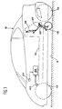
- FIG 1 there is shown very schematic, a single-track type vehicle conforming to the invention.
- This vehicle comprises a chassis 10, of which only a small part appears in the figure.
- This chassis 10 rests on the ground S by a front wheel steer 12 and a rear drive wheel 14.
- the wheels 12 and 14 are aligned along a median plane of the vehicle, parallel to the plane of Figure 1.
- this median plane is vertical.
- the front 12 and rear 14 wheels constitute the wheels of the vehicle.
- the vehicle according to the invention is also with a passenger compartment 16, preferably fully closed in the manner of a motor vehicle interior to four wheels. It thus offers comfort and safety comparable to that of such a vehicle, while being of reduced lateral dimensions and of a handling comparable to that of a motorcycle, as will be better understood later.
- the vehicle according to the invention is provided with, in addition to all functional equipment, safety and comfort usually fitted to motorcycles and four-wheeled motor vehicles wheels.
- This equipment (not shown) includes in particular an engine block ensuring the drive of the rear wheel 14, saddles or seats for the driver and at least one passenger and different controls and dials available to the driver.
- the vehicle according to the invention is also equipped, on both sides of its plan median, two lateral stabilizing wheels, designated by reference 18, only one of which is visible in Figure 1.
- the stabilizing wheels 18 are mounted on the chassis 10 of the vehicle, close to of the rear wheel 14 and slightly forward by compared to it.
- each of the wheels lateral stabilizers 18 is connected to chassis 10 of the vehicle by an articulated mechanism 20 which will described in detail later.
- This articulated mechanism is designed so that the wheel can be moved stabilizer 18 which it supports in a retracted state in an active state, and vice versa.
- the stabilizing wheels 18 When the stabilizing wheels 18 are in their retracted state, they are practically erased in all inside the passenger compartment envelope 16 of the vehicle, so that it behaves so totally like a motorcycle capable of bow down the corners.
- the stabilizing wheels 18 when they are in their active state, they came out of on either side of the passenger compartment 16 of the vehicle, so as to be able to constitute specific supports for stabilize it when the vehicle is stationary or moves at low speed.
- the lateral stabilizing wheels 18 automatically go from their retracted state into their active state when vehicle speed becomes below a predetermined threshold, and vice versa.
- the vehicle is provided with means 22 speed measurement.
- These means 22 can be constituted by any speed sensor capable to be mounted on a vehicle and in particular by a sensor placed on the front wheel 12 and providing by elsewhere a speed information to the driver of the vehicle.
- the vehicle is also equipped with suitable means 23 to detect an inclination of its median plane, by compared to the vertical.
- detection means 23 tilt can be made up by any means suitable, such as a mercury detector, accelerometer, etc.
- the means of tilt detection 23 comprising a pendulum 108, pivoting around an axis 110, fixed on the chassis of the vehicle, in the median plane thereof and according to its longitudinal axis.
- An inertial mass 112 which can be moved on the balance rod 108, used to adjust the sensitivity and amplitude of the oscillations of the balance.
- a metal plate 114 is fixed to the lower end of the pendulum rod 108.
- the tilt detection means 23 also include two inductive sensors 116, able to detect the presence of the metal plate 114. These sensors 116 are fixed to the chassis of the vehicle in a location such that the plate passes to about 2 mm in front of the sensor surface, when pendulum oscillations 108. In addition, the sensors 116 are located at a predetermined distance from the plane vehicle median, this distance corresponding to a inclination of about one degree of said median plane by compared to the vertical. Therefore, when the vehicle tilts at least one degree from vertically, the pendulum 108 rotates which brings the metal plate 114 in front of one of the inductive sensors 116. The latter detects the presence of metal and gives a signal until the plate 114 is no longer in front of the sensor.
- the vehicle according to the invention comprises of plus automatic wheel control means stabilizers 18, sensitive to vehicle speed measured by the speed measuring means 22, for automatically place the stabilizing wheels 18 in their retracted state or in their active state, depending on that the predetermined speed threshold is crossed in the direction of acceleration or in the direction of slowdown, respectively.
- the automatic control means include a circuit electronic, illustrated schematically at 24 on the Figure 1, and two pneumatic cylinders 26 for setting position, interposed between the chassis 10 and each of the articulated mechanisms 20.
- the electronic circuit 24 receives the signals speed emitted by the speed measuring means 22, compares them to a predetermined threshold which corresponds to the unstable equilibrium limit of the vehicle without stabilizers, and controls the emission of implementation of the two pneumatic actuating cylinders 26 in position, in either direction, depending on the results of this comparison.
- a predetermined threshold which corresponds to the unstable equilibrium limit of the vehicle without stabilizers
- the speed threshold can be set at around 20 km / h.
- the electronic circuit 24 also receives the tilt signals from inductive sensors 116. As will be described in more detail below, when the stabilizers are out, i.e. when the vehicle speed is below the threshold predetermined, the signals emitted by the sensors 116 are operated by the electronic circuit 24 for straighten the vehicle. In addition, the correction of tilt thus performed is proportional to the speed.
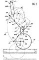
- each mechanism articulated 20 connects the lower end of the rod control 26a of the pneumatic cylinder 26 for setting position to a shaft 28 supporting the wheel stabilizer 18, so that it can rotate freely around its axis.
- the body 26b of the cylinder 26 is articulated by an axis 30 at chassis 10 or to a member integral therewith.
- the articulated mechanism 20 comprises a first link 32 of which one end is articulated on the chassis 10 or on a member secured thereto, by an axis 34.
- the end of the rod 26a of the jack 26 is articulated on this first link 32 by an axis articulation 36 relatively distant from the fixed axis 34.
- the second end of the link 32 is articulated on one end of a second link 38, by a hinge pin 40.
- the second end of this link 38 is itself articulated on a third link 42, by an axis 44.
- This axis of articulation 44 is relatively close to one end of the link 42, articulated on the chassis 10 or on a member linked to it chassis, by a fixed axis 46.
- the second end of the third link 42 is articulated on one end a fourth link 48, by a hinge pin 50.
- the second end of the link 48 carries the corresponding stabilizing wheel 18, by through the tree 28.
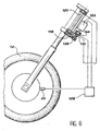
- damping means comprising preferably a pneumatic damper cylinder 52 are interposed between the rod 42, or an organ integral with it, and the link 48. So more precise, the lower end of the rod 52a of the jack 52 is articulated on the link 48 by an axis articulation 54 and the upper end of the body 52b of the jack 52 is articulated with a connecting piece 56, itself linked to the link 42.
- each wheel stabilizers 18 in the active state of each wheel stabilizers 18, determined by the state of elongation maximum of the actuating cylinder 26, the connecting rods 32 and 38 are aligned and tilted down and towards the rear from the fixed axis 34.
- the link 42 is then tilted down and forward from fixed axis 46, substantially forming an angle straight with the rods 32 and 38.
- the link 48 is then substantially horizontal and oriented towards the rear from the hinge pin 50.
- each of the wheels stabilizers 18 is located at a height predetermined H above a contact plane of the main wheels 12 and 14 of the vehicle with the ground, this contact plane being perpendicular to the median plane of the vehicle. Consequently, when the ground S is flat and horizontal, and when the vehicle is not tilted, each of the stabilizing wheels 18 is located at said predetermined height H above the ground.
- This height predetermined H is, for example, equal to at least 60 mm.
- the first link 32 pivots upwards around the fixed axis 34, for example around 60 °, as illustrated by arrow F1. Since the first link 32 is connected to the third link 42 by the second link 38, via the axes of articulation 40 and 44, this pivoting of the first rod causes pivoting in opposite direction to the third link 42 around the fixed axis 46, as this has been illustrated by the arrows F2. This pivoting, of which the amplitude is, for example, around 120 °, is also done upwards.
- the cylinder shock absorber 52 remains in its retracted state, so that the assembly constituted by the rods 42 and 48, the jack 52 and the wheel 18 turns without deforming around the fixed axis 46, to take the position illustrated in thin dashed line in Figure 2.
- This position corresponds to the retracted state of the wheels stabilizers 18.
- this state retracted is defined so that the wheels stabilizers are almost entirely retracted to inside the passenger compartment 16 and allow inclination of the median plane of the vehicle relative to the vertical, similar to that of a motorcycle, for example around 45 °.
- the stabilizer can, in case of power failure or pneumatic (or both), deploy and automatically lock in an emergency, without the intervention of any kind of energy.
- the stabilizer will stay in position only thanks to its kinematics, for the reasons previously cited.
- the maximum tilt of the median plane of the vehicle in this emergency corresponds then at height H. This arrangement constitutes a security which guarantees the stability of the vehicle at low speed and stationary, in such emergency conditions.
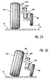
- the damping means comprising the pneumatic shock absorbers 52 have a adjustable stiffness and are actuated automatically, at the end of the deployment of the jacks 26, so as to bring the stabilizing wheels 18 in contact with the ground S, then to subject their rigidity to the speed measured by the means 22 (FIG. 1) for measuring the speed of the vehicle.
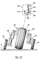
- This actuation step of the cylinders shock absorbers 52 allowing first of all to bring the stabilizing wheels 18 in contact with the ground S, is illustrated schematically in fine dotted line on the Figure 2, in the case where the stabilizing wheel 18 is then finds in front of a hole T in the ground. She is also illustrated in FIGS. 4A to 4C, respectively when the ground S is flat, when the stabilizer wheel 18 is in front of a bump B and when the stabilizing wheel 18 is opposite of a hole T.
- the damping cylinders 52 When the stabilizer is in position active, the damping cylinders 52 also serve to correct a possible inclination of the median plane of the vehicle with respect to the vertical, detected by one inductive sensors 116. Such an inclination can be due to centrifugal or soil force, which can present a significant slope.
- the recovery of the vehicle is carried out in matching the atmosphere, the room upper of the first damping cylinder 52, located on the side opposite to the triggered sensor 116. Bedroom upper of the second damping cylinder 52, is as to it connected to the setpoint pressure conversely proportional to the speed.
- the tilt correction thus performed is proportional to the speed. More the lower the speed, the more active the straightening (for example 0 bar in a cylinder and 7 bar in the opposite cylinder) and vice versa, the higher the speed closer to 20 km / h, the less active the turnaround (for example 0 bar in a cylinder and 1 bar in the cylinder opposite). In the latter case, the chassis geometry combined with the gyroscopic effect also intervene to keep the single track (inclined or not) in balanced.
- Each of the positioning cylinders 26 includes a superior bedroom and a bedroom lower.
- the dispenser 58 occupies its closed central position illustrated schematically on Figure 5.
- a compressed air supply line 60 connects an inlet port of the dispenser 58 to a compressed air source including in this case a main compressor 62 and a secondary compressor 64.
- a first outlet pipe 66 connects a first outlet of distributor 58 aux upper chambers of the positioning cylinders 26 and a second outlet pipe 68 connects a second outlet of distributor 58 aux lower chambers of the cylinders 26.
- the distributor 58 blocks the ends of the pipes 60, 66 and 68.
- Each of the pneumatic shock absorber cylinders 52 also includes a superior room, adjustment rigidity, and a lower chamber, control status retracted.
- shock absorbers tires 52 is provided by means of amortization regulation.
- These means of regulation damping include a circuit capable of supplying in compressed air the upper chamber of each of shock absorbers from the same air source compressed, i.e. from the compressor main 62 and secondary compressor 64.
- the line 70 Downstream of the voltage / pressure translator 72, the line 70 is connected to one of the two orifices inlet of a normally closed distributor 74.
- the second inlet of this distributor 74 is closed and normally connected to an outlet unique, able to be put in communication with the upper chamber of each of the shock absorber cylinders 52 by two separate pipes 76.
- Each of these pipelines 76 constitutes an independent circuit of pressure limitation for shock absorber cylinder 52 corresponding.
- the opening of the dispenser 74, putting in communication line 70 with each of lines 76, is controlled automatically by a signal emitted by the electronic circuit 24, as soon as the lateral stabilizing wheels 18 arrive in their active state.
- the non-return valves 78 are arranged to allow the passage of compressed air to the upper chambers of the shock absorber cylinders 52, all by preventing the flow of air in the opposite direction.
- Each of the quick exhaust valves 80 is a suitable means of comparing pressure effective prevailing in the upper chamber of the jack shock absorber 52 at the set pressure, established in line 70, downstream of the translator tension / pressure 72.
- Each of the quick exhaust valves 80 is controlled by a drawer, illustrated schematically at 84 in FIG. 5.
- This drawer 84 is sensitive to antagonistic pressures prevailing in the upstream parts and downstream of line 76. These pressures antagonists are the set pressure and the effective pressure in the upper chamber of the cylinder shock absorber 52.
- each of the shock absorber cylinders 52 When the pressure in the room upper of each of the shock absorber cylinders 52 is lower than the set pressure established by the voltage / pressure translator 72 (distributors 74 and 82 being open) the drawer 84 of the valve 80 quick exhaust is moved to the left in considering FIG. 5. The valve 80 then switches on communication the upstream and downstream parts of the corresponding line 76 and its orifice exhaust is blocked.
- the exhaust ports of the two valves 80 to quick exhaust are connected to the inlet port single from a common distributor 86 normally closed, by two lines 88 each of which is equipped with a non-return valve 90.
- a common distributor 86 normally closed, by two lines 88 each of which is equipped with a non-return valve 90.
- its inlet orifice communicates with a first closed outlet orifice.
- the electronic circuit 24 emits an excitation signal from the common distributor 86.
- the inlet port of the distributor is put in communication with a second outlet, to which is connected a exhaust pipe 92.
- a signal is emitted by the circuit electronic 24 and transmitted to distributors 82 or 94.
- the inductive sensor 116 located on the side of the incline emits a signal which has to operate the corresponding distributor 82 on the side opposite the slope.
- the drawer of this distributor 82 moves to the left so that connect line 76 to the exhaust of the distributor. So the pressure in the line 76 becomes equal to the atmosphere.
- the stroke of the cylinder 52 located on the side opposite to the inclination can easily decrease as measure that the jack 52 located on the side of the inclination, whose upper chamber is established at the pressure of setpoint, increases its stroke.
- the explanation is the same for an inclination of the median plane of the vehicle in the opposite direction.
- each of the pipes 76 relative to the valve 80, comprises a first part connected to a first inlet port of the distributor 82 corresponding, and a second part, connecting a single outlet of distributor 82 to the upper chamber of the damping cylinder 52 corresponding.
- these two parts of the downstream section of line 76 communicate with each other.
- the electronic circuit 24 delivers an excitation signal from each of the distributors 82. These pass then in a state in which their outlet is isolated from the first inlet and put in communication with a second inlet port of the distributor 82, connected to the outside atmosphere.
- the electronic circuit 24 When the vehicle speed rises above from the predetermined threshold defined above, the electronic circuit 24 emits an excitation signal from the distributor 94. Under the effect of this signal, the distributor 94 switches to a state in which its single outlet is connected to the second port inlet, communicating with compressors 62 and 64 by a line 100.
- the distributors 74 and 86 immediately switch to their open state and the voltage / pressure translator 72 is set work, in order to adjust the nominal pressure according of speed. In contrast, distributors 58, 82 and 94 remain in their nominal state.
- the nominal pressure at the outlet of the voltage / pressure translator 72 tends to decrease.
- the quick exhaust valves 80 allow pressure effective in the upper chambers of the cylinders shock absorbers 52 to follow this decrease, by putting in communication with the downstream section of each of the pipes 76 with the exhaust pipe 92, through distributor 86, then in position opened.
- the pressure in the rooms shock absorber cylinders 52 thus decreases gradually with the speed of the vehicle, such so that the handling of the latter approaches gradually that of a motorcycle as and when as the need for lateral stabilization vehicle efficiency is decreasing.
- the electronic circuit 24 When the predetermined speed threshold, for example of 20 km / h is reached, the electronic circuit 24 immediately issues orders to excite distributors 82 and 94, to ensure the return of shock absorbers 52.
- the limit switches 106 emit corresponding signals which are transmitted to electronic circuit 24.
- the electronic circuit 24 controls excitation of distributor 58, to the left in considering Figure 5. Therefore, the chambers upper cylinders 26 for positioning are vented while their rooms are put in communication with the compressors 62 and 64. The stabilizing wheels side are quickly returned to their state retracted.
- the circuit electronic 24 stops exciting distributors 58, 74, 82, 86 and 94.
- the electronic circuit 24 When the vehicle slows down and crosses the predetermined speed threshold, for example 20 km / h, in the direction of descent, the electronic circuit 24 immediately emits an excitation signal from the distributor 58.
- This excitation signal has the effect of move the dispenser drawer to the right by considering figure 5. So the rooms lower cylinders 26 for positioning are vented and the upper chambers of these cylinders are connected to compressors 62 and 64. By Consequently, the lateral stabilizing wheels 18 of the vehicle are brought into their active state, as as illustrated in FIGS. 3A and 3B, by a deployment of articulated mechanisms 20.
- exhaust valves 80 fast maintain, so independent, the pressure in the upper chamber of each of the damping cylinders 52 at the value of setpoint, even in the presence of unevenness on the ground which is located opposite the lateral stabilizing wheel 18 corresponding.
- each damper cylinder 52 has a stroke of 60 mm in compression and 100 mm in expansion.
- management can be electrically assisted.
- the wheel 118 driven by the worm 126 constitutes a motor speed reducer assembly electric 122.
- Motor 122 and clutch 124 are controlled by signals from a computer 128. This receives the signals delivered by the speed 22, and by a sensor 130 measuring the torque transmitted to the steering column and the direction of the rotation.
- the clutch 124 When the vehicle speed is higher at the threshold of deployment of the stabilizers (approximately 20 km / h), the clutch 124 is actuated so as to disconnect the motor 122 from the steering column. Below this speed threshold, the intensity of the assistance provided by the electric motor 122 is inversely proportional to speed and proportional to the steering torque.
- the invention is not limited to embodiment which has just been described as example, but covers all variants and equivalents technical, within the scope of the claims attached.
- these variants note the possibility to replace the pneumatic system described by a system hydraulic, by an oleopneumatic system with control of the precharge gas, or by an electrical system controlling the torque of the rod 48 of each articulated mechanism.
- a flexible cylinder as a shock absorber bellows associated with a single pneumatic cylinder effect, or any other variable length device, allowing to control the rigidity and being able to retract for minimal bulk.
- the electronic circuit 24 can also process signals from other sensors capable of measure for example the lateral acceleration of the vehicle, or the rotation of the handlebars. Thanks to an algorithm suitable the circuit is then able to control more precisely the angle of the median plane of the monotrace with vertical.
- the circuit then controls the ascent and descent of the stabilizer and corrects the tilt of the vehicle and the rigidity of the damping means, depending on the driver skills or conditions traffic, in addition to signals from different sensors.
- the voltage / pressure translator assembly, valves quick exhaust can be replaced with a classic closed loop servo, using two expensive self-regulating valves.
Landscapes
- Engineering & Computer Science (AREA)
- Mechanical Engineering (AREA)
- Chemical & Material Sciences (AREA)
- Combustion & Propulsion (AREA)
- Transportation (AREA)
- Vehicle Body Suspensions (AREA)
- Regulating Braking Force (AREA)
- Automatic Cycles, And Cycles In General (AREA)
- Axle Suspensions And Sidecars For Cycles (AREA)
- Arrangement Or Mounting Of Propulsion Units For Vehicles (AREA)
Claims (14)
- Fahrzeug vom Einspurtyp, umfassend einen Rahmen (10), der dazu ausgelegt ist, mittels zweier zueinander ausgerichteter Haupträder (12, 14) und zweier einziehbarer seitlicher Stabilisierungsräder (18) auf dem Boden (S) zu ruhen, wobei das Fahrzeug femer Mittel (22) zur Geschwindigkeitsmessung umfasst, die dazu ausgelegt sind, die Verlagerungsgeschwindigkeit des Fahrzeugs zu messen, sowie Mittel zur automatischen Steuerung (24, 58, 26) der Stabilisierungsräder (18), welche empfindlich sind für die von den Geschwindigkeitsmessmitteln (22) gemessene Geschwindigkeit, um die Stabilisierungsräder automatisch in einen eingezogenen Zustand zu plazieren, wenn die gemessene Geschwindigkeit eine vorbestimmte Schwelle überschreitet, und in einen aktiven Zustand, wenn die gemessene Geschwindigkeit kleiner als die Schwelle ist, dadurch gekennzeichnet, dass jedem der Stabilisierungsräder (18) Dämpfungsmittel (52) mit regelbarer Steifigkeit zugeordnet sind, und dass Dämpfungsregelungsmittel (72, 80) automatisch die Steifigkeit jedes der Dämpfungsmittel abhängig von der durch die Geschwindigkeitsmessmittel (22) gemessenen Geschwindigkeit im aktiven Zustand der Stabilisierungsräder (18) derart regeln, dass die Steifigkeit in umgekehrter Richtung zur gemessenen Geschwindigkeit variiert.
- Fahrzeug nach Anspruch 1, bei dem Mittel (23) vorgesehen sind, um eine Neigung der Mittelebene des Fahrzeugs bezüglich der Vertikalen zu erfassen, um im aktiven Zustand der Stabilisierungsräder (18) eine automatische Regelung der Steifigkeit jedes der Dämpfungsmittel (52) umgekehrt proportional zur Geschwindigkeit zu befehlen, um die Mittelebene in die Vertikale zurückzubringen.
- Fahrzeug nach einem der Ansprüche 1 und 2, bei dem die Dämpfungsmittel (52) einen zurückgezogenen Zustand einnehmen, wenn die Stabilierungsräder (18) in ihrem zurückgezogenen Zustand sind, und wenn die automatischen Steuermittel (24, 58, 26) dazu betätigt werden, ein Umschalten zwischen dem zurückgezogenen und dem aktiven Zustand der Stabilisierungsräder zu steuern.
- Fahrzeug nach Anspruch 3, bei dem dann, wenn die Stabilisierungsräder (18) in ihrem aktiven Zustand sind, und wenn die Dämpfungsmittel (52) ihren zurückgezogenen Zustand einnehmen, die Stabilisierungsräder (18) in einer vorbestimmten Höhe über einer Kontaktebene der Haupträder (12, 14) mit dem Boden liegen, wobei die Ebene orthogonal zu einer Mittelebene des Fahrzeugs ist.
- Fahrzeug nach Anspruch 4, bei dem erste Erfassungsmittel (104) vorgesehen sind, um einen Übergang der Stabilisierungsräder (18) in ihren aktiven Zustand zu erfassen, wobei die Dämpfungsregelungsmittel (72, 80) empfindlich sind für ein von den ersten Erfassungsmitteln geliefertes erstes Erfassungssignal, um automatisch eine Betätigung der Dämpfungsmittel (52) zu befehlen, bis die Stabilisierungsräder (18) in Kontakt mit dem Boden gelangt sind, und dann eine automatische Regelung der Steifigkeit der Dämpfungsmittel zu befehlen.
- Fahrzeug nach einem der Ansprüche 4 und 5, bei dem zweite Erfassungsmittel (106) vorgesehen sind, um einen Übergang der Dämpfungsmittel (52) in ihren zurückgezogenen Zustand zu erfassen, wobei die automatischen Steuermittel (24, 58, 26) empfindlich sind für ein von den zweiten Erfassungsmitteln geliefertes zweites Erfassungssignal, um automatisch die Stabilisierungsräder in ihren zurückgezogenen Zustand zu bringen.
- Fahrzeug nach einem der vorhergehenden Ansprüche, bei dem die jedem der Stabilisierungsräder (18) zugeordneten Dämpfungsmittel einen pneumatischen Dämpfungszylinder (52) umfassen.
- Fahrzeug nach einem der vorhergehenden Ansprüche, bei dem die Dämpfungsregelungsmittel einen Kreis zur Druckluftversorgung einer Steifigkeitsregelkammer jedes der Dämpfungsmittel (52) umfassen, wobei der Kreis eine Druckluftquelle (62, 64) und eine Einrichtung (72) umfasst, die dazu ausgelegt ist, den Druck der zu den Kammem geleiteten Druckluft auf einen Einstelldruck zu regeln, der umgekehrt proportional zu der von den Geschwindigkeitsmessmiteln (22) gemessenen Geschwindigkeit ist.
- Fahrzeug nach Anspruch 8, bei dem die Dämpfungsregelungsmittel ferner einen unabhängigen Druckbegrenzungskreis für jedes der Dämpfungsmittel (52) umfassen, wobei jeder Druckbegrenzungskreis dazu ausgelegt ist, die Steifigkeitsregelkammer eines der Dämpfungsmittel mit dem Versorgungskreis zu verbinden, und zwar mittels einer Einrichtung (80), die dazu ausgelegt ist, den in der Kammer herrschenden effektiven Druck mit dem Einstelldruck zu vergleichen, um diese Kammer in Verbindung mit dem Versorgungskreis zu bringen, wenn der effektive Druck kleiner als der Einstelldruck ist, und mit der Umgebung im entgegengesetzten Fall.
- Fahrzeug nach Anspruch 9, bei dem die Einrichtung, die dazu ausgelegt ist, den effektiven Druck mit dem Einstelldruck zu vergleichen, ein Schnellauslassventil (80) ist, das von einem Schieber gesteuert wird, der empfindlich ist für entgegensetzte Drücke entsprechend dem effektiven Druck und dem Einstelldruck.
- Fahrzeug nach einem der Ansprüche 9 und 10, bei dem ein normalerweise geschlossener Verteiler (86) zwischen der Umgebung und der Einrichtung (80) angeordnet ist, die dazu ausgelegt ist, den effektiven Druck mit dem Einstelldruck zu vergleichen, wobei beim Übergang der Stabilisierungsräder (18) in ihren aktiven Zustand automatisch ein Öffnen des Verteilers (86) befohlen wird.
- Fahrzeug nach einem der vorhergehenden Ansprüche, bei dem jedes der Stabilisierungsräder (18) mit dem Rahmen (10) mittels eines Mechanismus (20) verbunden ist, der dazu ausgelegt ist, sich automatisch durch Schwerkraft zu entfalten und sich zu verriegeln, um dieses Rad beim Ausfall der automatischen Steuermittel (24, 26) in den aktiven Zustand zu bringen.
- Fahrzeug nach einem der vorhergehenden Ansprüche, bei dem die automatischen Steuermittel zwei pneumatische Positionierungszylinder (26) umfassen, die jeweils mit zwei entgegengesetzten Steuerkammem versehen sind, welche dazu ausgelegt sind, mittels eines gemeinsamen Verteilers (58) mit geschlossener Mitte abwechselnd mit einer Druckluftquelle verbunden zu werden.
- Fahrzeug nach einem der vorhergehenden Ansprüche, bei dem Lenkunterstützungsmittel (122), die automatisch abgeschaltet werden, wenn die Fahrzeuggeschwindigkeit die Schwelle überschreitet, das Lenken des Fahrzeugs umgekehrt proportional zur Fahrzeuggeschwindigkeit und proportional zum von einem geeigneten Sensor (130) gemessenen Lenkmoment unterstützen.
Applications Claiming Priority (3)
| Application Number | Priority Date | Filing Date | Title |
|---|---|---|---|
| FR9815476A FR2786749B1 (fr) | 1998-12-08 | 1998-12-08 | Vehicule de type monotrace a roues stabilisatrices escamotables asservies a la vitesse |
| FR9815476 | 1998-12-08 | ||
| PCT/FR1999/003020 WO2000034112A1 (fr) | 1998-12-08 | 1999-12-06 | Vehicule de type monotrace a roues stabilisatrices escamotables asservies a la vitesse |
Publications (2)
| Publication Number | Publication Date |
|---|---|
| EP1137568A1 EP1137568A1 (de) | 2001-10-04 |
| EP1137568B1 true EP1137568B1 (de) | 2003-05-14 |
Family
ID=9533714
Family Applications (1)
| Application Number | Title | Priority Date | Filing Date |
|---|---|---|---|
| EP99957369A Expired - Lifetime EP1137568B1 (de) | 1998-12-08 | 1999-12-06 | Einspuhrfahrzeug mit von der geschwindigkeit abhängigen, ausschwenkbaren stabilisierungsrädern |
Country Status (6)
| Country | Link |
|---|---|
| EP (1) | EP1137568B1 (de) |
| AT (1) | ATE240233T1 (de) |
| AU (1) | AU1509600A (de) |
| DE (1) | DE69907952D1 (de) |
| FR (1) | FR2786749B1 (de) |
| WO (1) | WO2000034112A1 (de) |
Cited By (1)
| Publication number | Priority date | Publication date | Assignee | Title |
|---|---|---|---|---|
| US9776678B2 (en) | 2015-08-10 | 2017-10-03 | Two Wheels Technology, Co., Ltd. | Self-balancing vehicles |
Families Citing this family (10)
| Publication number | Priority date | Publication date | Assignee | Title |
|---|---|---|---|---|
| DE10146623A1 (de) * | 2001-06-27 | 2003-01-30 | Gerhard Baierlein | Motorisiertes Zweirad |
| DE10235576A1 (de) * | 2002-08-03 | 2004-02-19 | Bayerische Motoren Werke Ag | Stützradanordnung für Einspurfahrzeuge |
| JP2005535490A (ja) * | 2002-08-09 | 2005-11-24 | ペラフェス アクチェンゲゼルシャフト | 単軌道車両を安定させる装置および同装置を備えた車両 |
| US7006901B2 (en) * | 2002-11-18 | 2006-02-28 | Wang Everett X | Computerized automated dynamic control system for single-track vehicles |
| ITPI20030069A1 (it) * | 2003-09-17 | 2005-03-18 | Marco Doveri | Circuito elettroidraulico semplificato per un attuatore |
| ITMO20040002A1 (it) * | 2004-01-09 | 2004-04-09 | Meta System Spa | ,,dispositivo di stabilizzazione per motocicli e simili,,. |
| CN102358364B (zh) * | 2011-09-02 | 2014-12-31 | 深圳市宇恒互动科技开发有限公司 | 自行车骑行辅助装置、用该辅助装置的自行车及辅助方法 |
| IT201700006351A1 (it) * | 2017-01-20 | 2018-07-20 | Andrea Capovilla | “sistema di protezione” |
| CN108860375B (zh) * | 2018-07-18 | 2024-10-01 | 宝岛知仁(山东)新能源有限公司 | 一种具有失效保护功能的电动车起落架 |
| US11027786B2 (en) | 2018-11-20 | 2021-06-08 | Harley-Davidson Motor Company Group, LLC | Gyroscopic rider assist device |
Family Cites Families (4)
| Publication number | Priority date | Publication date | Assignee | Title |
|---|---|---|---|---|
| JPS5442745A (en) * | 1977-07-25 | 1979-04-04 | Honda Motor Co Ltd | Device for preventing fall down in autocycle |
| US5029894A (en) * | 1990-03-30 | 1991-07-09 | Willman David M | Retractable motorcycle stop-support wheels |
| US5378020A (en) * | 1991-03-01 | 1995-01-03 | Horn; Arthur | Stabilized high speed bi-wheeled vehicle |
| FR2735580B1 (fr) | 1995-06-14 | 1997-07-18 | Commissariat Energie Atomique | Accelerometre du type a compensation de l'effet de la pesanteur et procede de realisation d'un tel accelerometre |
-
1998
- 1998-12-08 FR FR9815476A patent/FR2786749B1/fr not_active Expired - Fee Related
-
1999
- 1999-12-06 AU AU15096/00A patent/AU1509600A/en not_active Abandoned
- 1999-12-06 EP EP99957369A patent/EP1137568B1/de not_active Expired - Lifetime
- 1999-12-06 AT AT99957369T patent/ATE240233T1/de not_active IP Right Cessation
- 1999-12-06 DE DE69907952T patent/DE69907952D1/de not_active Expired - Lifetime
- 1999-12-06 WO PCT/FR1999/003020 patent/WO2000034112A1/fr not_active Ceased
Cited By (1)
| Publication number | Priority date | Publication date | Assignee | Title |
|---|---|---|---|---|
| US9776678B2 (en) | 2015-08-10 | 2017-10-03 | Two Wheels Technology, Co., Ltd. | Self-balancing vehicles |
Also Published As
| Publication number | Publication date |
|---|---|
| DE69907952D1 (de) | 2003-06-18 |
| EP1137568A1 (de) | 2001-10-04 |
| AU1509600A (en) | 2000-06-26 |
| WO2000034112A1 (fr) | 2000-06-15 |
| FR2786749B1 (fr) | 2001-02-16 |
| FR2786749A1 (fr) | 2000-06-09 |
| ATE240233T1 (de) | 2003-05-15 |
Similar Documents
| Publication | Publication Date | Title |
|---|---|---|
| EP3041699B1 (de) | Dreirädriges neigefahrzeug | |
| EP1773609B1 (de) | Kraftfahrzeug mit begrenztem neigewinkel | |
| EP1137568B1 (de) | Einspuhrfahrzeug mit von der geschwindigkeit abhängigen, ausschwenkbaren stabilisierungsrädern | |
| EP1145879B1 (de) | Fahrzeug mit einer vertikalen, in der Radebene gelegenen, sturzveränderbaren Aufhängung | |
| EP2259936B1 (de) | Kraftfahrzeug mit gesteuerter neigung | |
| EP2542459A1 (de) | Elektrisches fahrzeug mit mindestens drei rädern | |
| FR2646379A1 (fr) | Dispositif hydraulique de commande de roulis d'un vehicule a trois roues inclinable | |
| FR2562843A1 (fr) | Dispositif de commande de la durete de la suspension d'un vehicule | |
| WO2012045963A1 (fr) | Engin agricole de pulvérisation et procède de pulvérisation d'un liquide phytosanitaire sur un terrain cultive au moyen d'un tel engin | |
| EP4087743B1 (de) | Fahrzeug mit einem chassis mit geregelter vertikaler lage, um in eine auf dem boden abgestützte niedrige position abgesenkt zu werden | |
| EP0354113B1 (de) | Vorrichtung zur Lageregelung eines Kraftfahrzeuges | |
| FR2872772A1 (fr) | Vehicule motorise a quatre roues | |
| FR2995255A1 (fr) | Systeme de liaison au sol pour vehicule inclinable, tel qu'un tricycle | |
| FR2566338A1 (fr) | Suspension de vehicule avec reglage de hauteur | |
| FR2802502A1 (fr) | Dispositif stabilisateur pour vehicule a deux roues | |
| WO2007087255A2 (en) | Stabilizing system for a motorcycle | |
| EP0440083B1 (de) | Vorrichtung zur Regulierung der Starrheit eines Reifens und Fahrzeug ausgerüstet mit solch einer Vorrichtung | |
| FR3105954A1 (fr) | Vehicule comprenant un chassis a position verticale commandee, et des dispositifs de blocage en rotation des bras de suspension lorsque le chassis se trouve en position basse d’appui sur le sol | |
| FR2543936A1 (fr) | Dispositif pour reduire la deviation oscillatoire d'un vehicule tel qu'une grue mobile pour terrains accidentes | |
| EP1169210B1 (de) | Fahrzeug mit geführter, variabler pendelung | |
| FR3058093A1 (fr) | Procede de controle de l'inclinaison d'un vehicule inclinable par action sur un dispositif de suspension hydropneumatique | |
| FR2518464A1 (fr) | Procede de stabilisation transversale automatique d'un vehicule, dispositif de stabilisation transversale automatique et vehicule comportant un tel dispositif | |
| FR2847224A1 (fr) | "2 roues" monotraces, optimises pour avoir un centre de gravite global(engin plus utilisateur(s))aussi bas que possible et equipements securitaires associes | |
| WO2021140293A1 (fr) | Procede ameliore d'abaissement d'un chassis de vehicule a position verticale commandee | |
| CA2302842A1 (fr) | Mecanisme de suspension ajustable |
Legal Events
| Date | Code | Title | Description |
|---|---|---|---|
| PUAI | Public reference made under article 153(3) epc to a published international application that has entered the european phase |
Free format text: ORIGINAL CODE: 0009012 |
|
| 17P | Request for examination filed |
Effective date: 20010525 |
|
| AK | Designated contracting states |
Kind code of ref document: A1 Designated state(s): AT BE CH CY DE DK ES FI FR GB GR IE IT LI LU MC NL PT SE |
|
| AX | Request for extension of the european patent |
Free format text: AL;LT;LV;MK;RO;SI |
|
| GRAH | Despatch of communication of intention to grant a patent |
Free format text: ORIGINAL CODE: EPIDOS IGRA |
|
| GRAH | Despatch of communication of intention to grant a patent |
Free format text: ORIGINAL CODE: EPIDOS IGRA |
|
| GRAA | (expected) grant |
Free format text: ORIGINAL CODE: 0009210 |
|
| AK | Designated contracting states |
Designated state(s): AT BE CH CY DE DK ES FI FR GB GR IE IT LI LU MC NL PT SE |
|
| PG25 | Lapsed in a contracting state [announced via postgrant information from national office to epo] |
Ref country code: NL Free format text: LAPSE BECAUSE OF FAILURE TO SUBMIT A TRANSLATION OF THE DESCRIPTION OR TO PAY THE FEE WITHIN THE PRESCRIBED TIME-LIMIT Effective date: 20030514 Ref country code: IT Free format text: LAPSE BECAUSE OF FAILURE TO SUBMIT A TRANSLATION OF THE DESCRIPTION OR TO PAY THE FEE WITHIN THE PRESCRIBED TIME-LIMIT;WARNING: LAPSES OF ITALIAN PATENTS WITH EFFECTIVE DATE BEFORE 2007 MAY HAVE OCCURRED AT ANY TIME BEFORE 2007. THE CORRECT EFFECTIVE DATE MAY BE DIFFERENT FROM THE ONE RECORDED. Effective date: 20030514 Ref country code: IE Free format text: LAPSE BECAUSE OF FAILURE TO SUBMIT A TRANSLATION OF THE DESCRIPTION OR TO PAY THE FEE WITHIN THE PRESCRIBED TIME-LIMIT Effective date: 20030514 Ref country code: GB Free format text: LAPSE BECAUSE OF FAILURE TO SUBMIT A TRANSLATION OF THE DESCRIPTION OR TO PAY THE FEE WITHIN THE PRESCRIBED TIME-LIMIT Effective date: 20030514 Ref country code: FI Free format text: LAPSE BECAUSE OF FAILURE TO SUBMIT A TRANSLATION OF THE DESCRIPTION OR TO PAY THE FEE WITHIN THE PRESCRIBED TIME-LIMIT Effective date: 20030514 Ref country code: AT Free format text: LAPSE BECAUSE OF FAILURE TO SUBMIT A TRANSLATION OF THE DESCRIPTION OR TO PAY THE FEE WITHIN THE PRESCRIBED TIME-LIMIT Effective date: 20030514 |
|
| REG | Reference to a national code |
Ref country code: GB Ref legal event code: FG4D Free format text: NOT ENGLISH |
|
| REG | Reference to a national code |
Ref country code: CH Ref legal event code: EP |
|
| REG | Reference to a national code |
Ref country code: IE Ref legal event code: FG4D Free format text: FRENCH |
|
| REF | Corresponds to: |
Ref document number: 69907952 Country of ref document: DE Date of ref document: 20030618 Kind code of ref document: P |
|
| PG25 | Lapsed in a contracting state [announced via postgrant information from national office to epo] |
Ref country code: SE Free format text: LAPSE BECAUSE OF FAILURE TO SUBMIT A TRANSLATION OF THE DESCRIPTION OR TO PAY THE FEE WITHIN THE PRESCRIBED TIME-LIMIT Effective date: 20030814 Ref country code: PT Free format text: LAPSE BECAUSE OF FAILURE TO SUBMIT A TRANSLATION OF THE DESCRIPTION OR TO PAY THE FEE WITHIN THE PRESCRIBED TIME-LIMIT Effective date: 20030814 Ref country code: GR Free format text: LAPSE BECAUSE OF FAILURE TO SUBMIT A TRANSLATION OF THE DESCRIPTION OR TO PAY THE FEE WITHIN THE PRESCRIBED TIME-LIMIT Effective date: 20030814 Ref country code: DK Free format text: LAPSE BECAUSE OF FAILURE TO SUBMIT A TRANSLATION OF THE DESCRIPTION OR TO PAY THE FEE WITHIN THE PRESCRIBED TIME-LIMIT Effective date: 20030814 |
|
| PG25 | Lapsed in a contracting state [announced via postgrant information from national office to epo] |
Ref country code: DE Free format text: LAPSE BECAUSE OF FAILURE TO SUBMIT A TRANSLATION OF THE DESCRIPTION OR TO PAY THE FEE WITHIN THE PRESCRIBED TIME-LIMIT Effective date: 20030815 |
|
| PG25 | Lapsed in a contracting state [announced via postgrant information from national office to epo] |
Ref country code: ES Free format text: LAPSE BECAUSE OF FAILURE TO SUBMIT A TRANSLATION OF THE DESCRIPTION OR TO PAY THE FEE WITHIN THE PRESCRIBED TIME-LIMIT Effective date: 20030825 |
|
| NLV1 | Nl: lapsed or annulled due to failure to fulfill the requirements of art. 29p and 29m of the patents act | ||
| GBV | Gb: ep patent (uk) treated as always having been void in accordance with gb section 77(7)/1977 [no translation filed] |
Effective date: 20030514 |
|
| PG25 | Lapsed in a contracting state [announced via postgrant information from national office to epo] |
Ref country code: LU Free format text: LAPSE BECAUSE OF NON-PAYMENT OF DUE FEES Effective date: 20031206 Ref country code: CY Free format text: LAPSE BECAUSE OF FAILURE TO SUBMIT A TRANSLATION OF THE DESCRIPTION OR TO PAY THE FEE WITHIN THE PRESCRIBED TIME-LIMIT Effective date: 20031206 |
|
| PG25 | Lapsed in a contracting state [announced via postgrant information from national office to epo] |
Ref country code: MC Free format text: LAPSE BECAUSE OF NON-PAYMENT OF DUE FEES Effective date: 20031231 Ref country code: LI Free format text: LAPSE BECAUSE OF NON-PAYMENT OF DUE FEES Effective date: 20031231 Ref country code: CH Free format text: LAPSE BECAUSE OF NON-PAYMENT OF DUE FEES Effective date: 20031231 Ref country code: BE Free format text: LAPSE BECAUSE OF NON-PAYMENT OF DUE FEES Effective date: 20031231 |
|
| REG | Reference to a national code |
Ref country code: IE Ref legal event code: FD4D Ref document number: 1137568E Country of ref document: IE |
|
| PLBE | No opposition filed within time limit |
Free format text: ORIGINAL CODE: 0009261 |
|
| STAA | Information on the status of an ep patent application or granted ep patent |
Free format text: STATUS: NO OPPOSITION FILED WITHIN TIME LIMIT |
|
| 26N | No opposition filed |
Effective date: 20040217 |
|
| BERE | Be: lapsed |
Owner name: *LHERMITTE DAMIEN Effective date: 20031231 Owner name: *GILLET PIERRE Effective date: 20031231 |
|
| REG | Reference to a national code |
Ref country code: CH Ref legal event code: PL |
|
| PG25 | Lapsed in a contracting state [announced via postgrant information from national office to epo] |
Ref country code: FR Free format text: LAPSE BECAUSE OF NON-PAYMENT OF DUE FEES Effective date: 20040831 |
|
| REG | Reference to a national code |
Ref country code: FR Ref legal event code: ST |