EP1137909B1 - Körperscanvorrichtung - Google Patents
Körperscanvorrichtung Download PDFInfo
- Publication number
- EP1137909B1 EP1137909B1 EP99973430A EP99973430A EP1137909B1 EP 1137909 B1 EP1137909 B1 EP 1137909B1 EP 99973430 A EP99973430 A EP 99973430A EP 99973430 A EP99973430 A EP 99973430A EP 1137909 B1 EP1137909 B1 EP 1137909B1
- Authority
- EP
- European Patent Office
- Prior art keywords
- scanning
- equipment
- sets
- scan
- scanning means
- Prior art date
- Legal status (The legal status is an assumption and is not a legal conclusion. Google has not performed a legal analysis and makes no representation as to the accuracy of the status listed.)
- Expired - Lifetime
Links
- 238000005286 illumination Methods 0.000 claims description 7
- 238000004441 surface measurement Methods 0.000 claims description 2
- 238000009434 installation Methods 0.000 abstract 1
- 238000005259 measurement Methods 0.000 description 6
- 238000004519 manufacturing process Methods 0.000 description 2
- 238000000034 method Methods 0.000 description 2
- 230000003287 optical effect Effects 0.000 description 2
- 238000010586 diagram Methods 0.000 description 1
Images

Classifications
-
- G—PHYSICS
- G01—MEASURING; TESTING
- G01B—MEASURING LENGTH, THICKNESS OR SIMILAR LINEAR DIMENSIONS; MEASURING ANGLES; MEASURING AREAS; MEASURING IRREGULARITIES OF SURFACES OR CONTOURS
- G01B11/00—Measuring arrangements characterised by the use of optical techniques
- G01B11/24—Measuring arrangements characterised by the use of optical techniques for measuring contours or curvatures
- G01B11/245—Measuring arrangements characterised by the use of optical techniques for measuring contours or curvatures using a plurality of fixed, simultaneously operating transducers
Definitions
- This invention relates to body scanning equipment and, in particular, although not exclusively to, a body scanning equipment for use in the garment industry.
- Body scanning apparatus is known to produce prosthesis, for example, but such equipment tends to be large in size and extremely costly.
- a further problem is one of the size of a scanning booth in which the scanning devices are located.
- Typical known scanning devices work best at ranges of about 2 metres from the surface to be scanned.
- closer ranges are possible if the capture field of view of the scanning device is reduced, or if very wide optics are used on the scanning device.
- a smaller field of view leads to the requirement of additional scanning devices with consequential greater cost, and wide angle optics give greater distortion and, therefore, lower accuracy, as well as being costly.
- the present invention seeks to provide a body scanning equipment which substantially mitigates the foregoing disadvantages.
- a body scanning equipment including one set of apparatus locate to scan a portion of a body, said set of apparatus comprising scanning means, reflector means associated with said scanning means, said reflector means including first and second reflectors spaced on opposing sides of said scanning means for directing radiant energy from opposing sides of said body, and switchable reflector means for directing radiant energy alternately between said scanning means and said first and second reflectors whereby substantially a 180° scan of said body may be made.
- Such a set of apparatus may be used, for example, in a medical environment where it is desired to scan a face of a person.
- a body scanning equipment including two sets of apparatus located to scan opposing front and rear portions of a body to be scanned and each set of apparatus comprising scanning means, reflector means associated with each scanning means, each said reflector means including first and second reflectors spaced on opposing sides of said scanning means for directing radiant energy from opposing sides of said body, and switchable reflector means for directing radiant energy alternately between said scanning means and said first and second reflectors, whereby a complete 360° scan of said body may be made.
- the scanning means may comprising a camera having a viewing axis and an illumination means having an illumination axis which is offset from said camera viewing axis.
- each pair being located in a different elevational position with respect to said body so that each pair is able to scan a whole portion of a body and the elevational location of the pairs being arranged such that a complete body may be scanned.
- said first and second reflectors and said switchable reflector means are each formed by a respective mirror.
- said sets of apparatus are mounted in a booth, typically approximately 2 metres square and about 2.4 metres high.
- each scanning means provides an output signal to processor means including means for computing surface data from images received from each opposing side of said body, means for producing aligned data from said surface data, means for producing a signal from said aligned data indicative of the surfaces of said body joinedtogether through 360°, and means for calculating surface measurements derived from said means for producing.
- said means for calculating is connected to a numerically controlled garment cutting machine which may in turn be connected to an automated garment assembly apparatus.
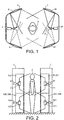
- the body scanning equipment shown in Figures 1 and 2 is located within a booth 1 shown in the drawings as two separate halves, although the booth may be a single member having a door.
- the booth typically has dimensions of approximately 2 metres square and about 2.4 metres in height.
- a body 2 of a customer to be scanned Approximately centrally located within the booth is shown a body 2 of a customer to be scanned.
- the body scanning apparatus includes, in the exemplary embodiment, four sets of apparatus arranged in two pairs. A first pair of sets of apparatus is arranged to scan the top portion of the body 2 and the second pair of sets of apparatus is arranged to scan the lower portion of the body 2.
- Each set of a pair of apparatus is arranged to scan either a front or a rear portion of the body 2. Because each set of apparatus is the same as the other sets, the invention will be described in relation to a single set of apparatus.
- Each set of apparatus has a scanning device 4 comprising, as shown in Figure 3, a camera 241 having a viewing axis and an illumination device, such as a lamp 242, having an illumination axis which is different from the viewing axis of the camera.
- the illumination axis of the lamp 242 is, preferably, at a different elevation from the viewing axis of the camera 241, although such is not essential.
- a pair of inclined mirrors 5, 6 are attached on each side of the optical axis of the scanning device 4 so as to direct radiant energy to a respective side of the body 2.
- a pivotable mirror 7 is located in front of the scanning device 4 so as to alternately reflect radiant energy to a respective one of the mirrors 5 or 6. By pivotally skewing the mirror 7 between two positions, two effective scanner positions are derived from a single scanning device 4.
- the other set of apparatus on the same elevational level as the scanning device 4 and the mirrors 5, 6 and 7 is denoted by reference numerals 41, 51, 61 and 71 respectively. Scans are made sequentially with the pivotable mirror 7, 71 in each of its two positions so that the complete 360° of a body surface may be scanned with just two scanning devices.
- a further pair of sets of apparatus are provided elevationally below the above-mentioned pair of sets of apparatus and are denoted by reference numerals 104, 105, 106, 107 and 141, 151, 161 and 171, so that the whole 360° and whole height of the body 2 may be scanned.
- the lamp 242 of each scanning device projects a pattern of light onto the surface of the body 2.
- the pattern of light may be obtained by a sequential series of light scans formed of narrow slits of light which are respectively projected onto different elevational locations of the body or, more usually, light is shone through a grating having plural horizontal slits therein.
- the body is scanned by the camera 241 and the data is processed to obtain three-dimensional surface co-ordinate data.
- the pattern of light that is projected comprising a series of horizontal lines is deflected by the contours of the surface of the body so that the lines appear bent when viewed at an offset angle by the camera 241. Using a sequence of such line patterns, and applying triangulation calculations to the amount by which the lines have been deflected up or down at each point on the surface, allows the surface contours to be mapped.
- each of the four scanning devices captures two images, one from each position of the pivotable mirror 4, 41, 104, 141.
- a total of eight three-dimensional images are produced which represent eight overlapping sections of the surface of the body 2.
- Output from the camera of the scanning devices is applied to a processor 100.
- the image data from the respective positions of the mirror 7, 71, 104, 141 is computed 101 and the computed surfaces are aligned 102.
- the aligned surfaces are joined together at step 103 where a three-dimensional representation of the whole body surface is produced. Having obtained the three-dimensional representation of the surface of the body, automated measurements are taken from the surface data at step 104 to be used in much the same way as a tailor on the actual person.
- the measurements are made more quickly, non-invasively, and with greater accuracy and consistency than can be achieved manually.
- the measurements may be supplied as output signals to a garment material cutting machine 111, known per se, and to a garment assembly unit 112, known per se , so that custom fitted clothing is provided.
- the foregoing invention overcomes the problems of cost and size and the invention provides an accurate match in geometric accuracy and colour between pairs of image sections taken with the same scanning device.
- the invention by using the novel optical arrangement, reduces the amount of software data processing that is needed to match the sections of image in order to make a seamless, all round, surface.
Landscapes
- General Physics & Mathematics (AREA)
- Physics & Mathematics (AREA)
- Treatment Of Fiber Materials (AREA)
- Length Measuring Devices By Optical Means (AREA)
- Vehicle Body Suspensions (AREA)
- Registering, Tensioning, Guiding Webs, And Rollers Therefor (AREA)
- Crystals, And After-Treatments Of Crystals (AREA)
- Glass Compositions (AREA)
- Investigating Or Analyzing Materials By The Use Of Ultrasonic Waves (AREA)
- Measurement Of Mechanical Vibrations Or Ultrasonic Waves (AREA)
- Eye Examination Apparatus (AREA)
- Closed-Circuit Television Systems (AREA)
- Image Input (AREA)
- Aerials With Secondary Devices (AREA)
- Optical Radar Systems And Details Thereof (AREA)
- Mechanical Optical Scanning Systems (AREA)
Claims (9)
- Einheit zum Scannen von Körpern, die eine Vorrichtungsanordnung (1) aufweist, die zum Abtasten eines Abschnitts eines Körpers (2) angeordnet ist, wobei die Vorrichtungsanordnung folgendes umfasst: eine Abtasteinrichtung (4), eine Reflektoreinrichtung (5, 6), die der Abtasteinrichtung zugeordnet ist, wobei die Reflektoreinrichtung erste und zweite Reflektoren aufweist, die an entgegengesetzten Seiten der Abtasteinrichtungen mit Zwischenabstand angeordnet sind, so dass Strahlungsenergie auf entgegengesetzte Seiten des Körpers gerichtet wird, und mit einer umschaltbaren Reflektoreinrichtung (7), die dazu dient, Strahlungsenergie wechselweise zwischen der Abtasteinrichtung und den ersten und zweiten Reflektoren zu richten, wodurch im wesentlichen eine Abtastung des Körpers um 180° durchgeführt werden kann.
- Einheit nach Anspruch 1, wobei zwei Vorrichtungsanordnungen vorgesehen sind.
- Einheit zum Scannen von Körpern, die zwei Vorrichtungsanordnungen (1) aufweist, die so positioniert sind, dass sie entgegengesetzte vordere und hintere Abschnitte eines abzutastenden Körpers (2) abtasten, und wobei jede Vorrichtungsanordnung folgendes umfasst: eine Abtasteinrichtung (4; 41), eine jeder Abtasteinrichtung zugeordnete Reflektoreinrichtung (5, 6; 51, 61), wobei jede Reflektoreinrichtung erste und zweite Reflektoren aufweist, die an entgegengesetzten Seiten der Abtasteinrichtung mit Zwischenabstand angeordnet sind, so dass Strahlungsenergie auf entgegengesetzte Seiten des Körpers gerichtet wird, und mit einer umschaltbaren Reflektoreinrichtung (7; 71), die dazu dient, Strahlungsenergie wechselweise zwischen der Abtasteinrichtung und den ersten und zweiten Reflektoren zu richten, wodurch eine vollständige Abtastung des Körpers um 360° durchgeführt werden kann.
- Einheit nach Anspruch 3, wobei die Abtasteinrichtung eine Kamera (241) mit einer Sichtachse und eine Beleuchtungseinrichtung (242) mit einer Beleuchtungsachse umfasst, die von der Sichtachse der Kamera versetzt ist.
- Einheit nach Anspruch 3 oder 4, wobei zwei Paare von Vorrichtungsanordnungen vorgesehen sind, wobei jedes Paar an einer anderen Höhenposition im Verhältnis zu dem Körper angeordnet ist, so dass jedes Paar einen gesamten Körperabschnitt abtasten kann, und wobei die Höhenposition der Paare so angeordnet ist, dass ein ganzer Körper abgetastet werden kann.
- Einheit nach Anspruch 3, 4 oder 5, wobei die ersten und zweiten Reflektoren und der umschaltbare Reflektor jeweils durch einen entsprechenden Spiegel gebildet werden.
- Einheit nach einem der Ansprüche 3 bis 6, wobei die Vorrichtungsanordnungen in einer Kabine angebracht sind, die kennzeichnenderweise eine Größe von ungefähr zwei Quadratmetern und eine Höhe von etwa 2,4 Metern aufweist.
- Einheit nach einem der vorstehenden Ansprüche, wobei jede Abtasteinrichtung ein Ausgangssignal an eine Prozessoreinrichtung (100) vorsieht, die folgendes aufweist: eine Einrichtung (101) zur Berechnung von Oberflächendaten aus den von jeder entgegengesetzten Seite des Körpers empfangenen Bildern, eine Einrichtung (102) zur Erzeugung ausgerichteter Daten aus den Oberflächendaten, eine Einrichtung (103) zur Erzeugung eines Signals aus den ausgerichteten Daten, das die über 360° zusammengeführten Oberflächen des Körpers anzeigt, und eine Einrichtung (104) zur Berechnung von Oberflächenmessungen, die von der Einrichtung zur Erzeugung abgeleitet werden.
- Einheit nach Anspruch 8, wobei die Einrichtung zur Berechnung mit einer nummerisch gesteuerten Schneidemaschine (111) für Kleidungsstücke verbunden ist, die wiederum mit einer automatisierten Vorrichtung (112) zur Fertigung von Kleidungsstücken verbunden sein kann.
Applications Claiming Priority (3)
| Application Number | Priority Date | Filing Date | Title |
|---|---|---|---|
| GB9827384A GB2345750B (en) | 1998-12-11 | 1998-12-11 | Body scanning equipment |
| GB9827384 | 1998-12-11 | ||
| PCT/GB1999/003821 WO2000036370A1 (en) | 1998-12-11 | 1999-11-16 | Body scanning equipment |
Publications (2)
| Publication Number | Publication Date |
|---|---|
| EP1137909A1 EP1137909A1 (de) | 2001-10-04 |
| EP1137909B1 true EP1137909B1 (de) | 2002-12-11 |
Family
ID=10844111
Family Applications (1)
| Application Number | Title | Priority Date | Filing Date |
|---|---|---|---|
| EP99973430A Expired - Lifetime EP1137909B1 (de) | 1998-12-11 | 1999-11-16 | Körperscanvorrichtung |
Country Status (12)
| Country | Link |
|---|---|
| US (1) | US6734980B1 (de) |
| EP (1) | EP1137909B1 (de) |
| JP (1) | JP2002532702A (de) |
| AT (1) | ATE229640T1 (de) |
| AU (1) | AU769044B2 (de) |
| CA (1) | CA2354553A1 (de) |
| DE (1) | DE69904506T2 (de) |
| ES (1) | ES2186443T3 (de) |
| GB (1) | GB2345750B (de) |
| NZ (1) | NZ512071A (de) |
| WO (1) | WO2000036370A1 (de) |
| ZA (1) | ZA200104501B (de) |
Families Citing this family (17)
| Publication number | Priority date | Publication date | Assignee | Title |
|---|---|---|---|---|
| WO2001065861A2 (en) * | 2000-03-02 | 2001-09-07 | Roane Jerry M | Method and apparatus for recording multiple perspective images |
| DE10132226A1 (de) * | 2001-06-29 | 2003-01-16 | Kpv Ag Bern | Verfahren zur Herstellung einer dreidimensionalen Kopie von einem als Vorlage dienenden Körper und Anlage zur Durchführung des Verfahrens |
| DE102004036491B4 (de) | 2004-07-28 | 2026-01-29 | Avalution Gmbh | Verfahren und Vorrichtung zur Herstellung von individuellen Modellpuppen |
| DE102008015499C5 (de) * | 2008-03-25 | 2013-01-10 | Steinbichler Optotechnik Gmbh | Verfahren und Vorrichtung zur Bestimmung der 3D-Koordinaten eines Objekts |
| DE102008024559A1 (de) * | 2008-05-21 | 2009-11-26 | Technische Universität Braunschweig Carolo-Wilhelmina | 3D-Geometrieerfassungsvorrichtung |
| CN102498363B (zh) * | 2009-09-15 | 2015-11-25 | 梅特勒-托利多公开股份有限公司 | 测量物体尺寸的设备 |
| US20120206587A1 (en) * | 2009-12-04 | 2012-08-16 | Orscan Technologies Ltd | System and method for scanning a human body |
| DE102012204537A1 (de) * | 2012-03-21 | 2013-09-26 | rocket eleven GmbH | Verfahren zum Bestimmen der Abmessungen eines Körperteils |
| US8926454B2 (en) | 2012-05-07 | 2015-01-06 | Karsten Manufacturing Corporation | Fitting systems for golf equipment using camera image for measurement of individual, and related methods |
| EP2720189A1 (de) * | 2012-10-11 | 2014-04-16 | Metria Digital, S.L. | Fotogrammetrisches System und Verfahren zur Erzeugung dreidimensionaler Avatare |
| US10945639B2 (en) * | 2013-01-16 | 2021-03-16 | Van De Velde Nv | Fitting room mirror |
| EP3064894B1 (de) * | 2015-03-03 | 2019-04-17 | Mohn Media Mohndruck GmbH | 3d-scanvorrichtung und verfahren zum bestimmen einer digitalen 3d-repräsentation einer person |
| CN106546188B (zh) * | 2016-11-05 | 2019-03-22 | 北京工业大学 | 一种用于人体3d扫描的两自由度调整机构 |
| US11246366B2 (en) * | 2017-05-31 | 2022-02-15 | Nike, Inc. | Selective deposition of reflective materials for an apparel item |
| CN108489390A (zh) * | 2018-04-09 | 2018-09-04 | 辽宁昭融瑞合工业数据有限公司 | 一种3d光学尺寸检测仪及光学尺寸检测系统 |
| KR200493579Y1 (ko) * | 2019-08-27 | 2021-04-28 | 주식회사 엘지유플러스 | 스마트폰 기반 3차원 스캐닝 장치 |
| PL438987A1 (pl) | 2021-09-20 | 2023-03-27 | Eduroco Spółka Z Ograniczoną Odpowiedzialnością | Urządzenie oraz system do skanowania obiektów, zwłaszcza sylwetki człowieka |
Family Cites Families (15)
| Publication number | Priority date | Publication date | Assignee | Title |
|---|---|---|---|---|
| US3383770A (en) * | 1964-01-22 | 1968-05-21 | James J. Xenakis | Clothing measuring method and apparatus |
| SE430924B (sv) * | 1982-05-28 | 1983-12-19 | Harald Kleinhuber | Anordning for dimensionsmetning av cylindriska foremal medelst en svepande laserstrale |
| GB8300512D0 (en) * | 1983-01-10 | 1983-02-09 | Cruickshank J S | Profile imaging techniques |
| US4901084A (en) * | 1988-04-19 | 1990-02-13 | Millitech Corporation | Object detection and location system |
| IE862086L (en) * | 1986-08-05 | 1988-02-05 | Bramleigh Ass Ltd | Glass inspection |
| US4982438A (en) * | 1987-06-02 | 1991-01-01 | Hitachi, Ltd. | Apparatus and method for recognizing three-dimensional shape of object |
| GB8719951D0 (en) | 1987-08-24 | 1987-09-30 | Lbp Partnership | Three-dimensional scanner |
| DE4037383A1 (de) | 1990-11-20 | 1992-05-21 | Mesacon Messtechnik | Verfahren zum kontinuierlichen beruehrungsfreien messen von profilen und einrichtung zur durchfuehrung des messverfahrens |
| GB9127139D0 (en) * | 1991-12-20 | 1992-02-19 | 3D Scanners Ltd | Scanning unit |
| GB9127548D0 (en) * | 1991-12-31 | 1992-02-19 | 3D Scanners Ltd | Scanning sensor |
| JPH07313492A (ja) * | 1994-05-26 | 1995-12-05 | Terumo Corp | 体格測定装置 |
| US6028672A (en) * | 1996-09-30 | 2000-02-22 | Zheng J. Geng | High speed three dimensional imaging method |
| JP3940826B2 (ja) * | 1996-08-29 | 2007-07-04 | 浜松ホトニクス株式会社 | 三次元形状計測装置 |
| US5956525A (en) * | 1997-08-11 | 1999-09-21 | Minsky; Jacob | Method of measuring body measurements for custom apparel manufacturing |
| DE19753246C2 (de) | 1997-12-01 | 2002-11-28 | Roland Seifert | Vorrichtung zur Bestimmung von dreidimensionalen Daten von Objekten |
-
1998
- 1998-12-11 GB GB9827384A patent/GB2345750B/en not_active Expired - Fee Related
-
1999
- 1999-11-16 AU AU11693/00A patent/AU769044B2/en not_active Ceased
- 1999-11-16 NZ NZ512071A patent/NZ512071A/xx unknown
- 1999-11-16 AT AT99973430T patent/ATE229640T1/de not_active IP Right Cessation
- 1999-11-16 ES ES99973430T patent/ES2186443T3/es not_active Expired - Lifetime
- 1999-11-16 DE DE69904506T patent/DE69904506T2/de not_active Expired - Fee Related
- 1999-11-16 EP EP99973430A patent/EP1137909B1/de not_active Expired - Lifetime
- 1999-11-16 US US09/857,534 patent/US6734980B1/en not_active Expired - Fee Related
- 1999-11-16 WO PCT/GB1999/003821 patent/WO2000036370A1/en not_active Ceased
- 1999-11-16 JP JP2000588566A patent/JP2002532702A/ja active Pending
- 1999-11-16 CA CA002354553A patent/CA2354553A1/en not_active Abandoned
-
2001
- 2001-05-31 ZA ZA200104501A patent/ZA200104501B/xx unknown
Also Published As
| Publication number | Publication date |
|---|---|
| US6734980B1 (en) | 2004-05-11 |
| CA2354553A1 (en) | 2000-06-22 |
| ZA200104501B (en) | 2002-05-31 |
| EP1137909A1 (de) | 2001-10-04 |
| GB9827384D0 (en) | 1999-02-03 |
| ES2186443T3 (es) | 2003-05-01 |
| NZ512071A (en) | 2003-01-31 |
| ATE229640T1 (de) | 2002-12-15 |
| JP2002532702A (ja) | 2002-10-02 |
| DE69904506T2 (de) | 2003-09-04 |
| GB2345750B (en) | 2002-12-18 |
| WO2000036370A1 (en) | 2000-06-22 |
| GB2345750A (en) | 2000-07-19 |
| DE69904506D1 (de) | 2003-01-23 |
| AU769044B2 (en) | 2004-01-15 |
| AU1169300A (en) | 2000-07-03 |
Similar Documents
| Publication | Publication Date | Title |
|---|---|---|
| EP1137909B1 (de) | Körperscanvorrichtung | |
| USRE39978E1 (en) | Scanning phase measuring method and system for an object at a vision station | |
| US3894802A (en) | Stereoscopic gage and gaging system | |
| US6147760A (en) | High speed three dimensional imaging method | |
| US6341016B1 (en) | Method and apparatus for measuring three-dimensional shape of object | |
| CN102792124B (zh) | 增强的成像方法及装置 | |
| JP5615998B2 (ja) | 物体を走査する装置 | |
| US4842411A (en) | Method of automatically measuring the shape of a continuous surface | |
| JP4226550B2 (ja) | 光学式マーカーを用いた三次元測定データ自動整列装置及びその方法 | |
| US20030160970A1 (en) | Method and apparatus for high resolution 3D scanning | |
| US20150015701A1 (en) | Triangulation scanner having motorized elements | |
| US3837198A (en) | Stereoscopic gage and gaging system | |
| US6765606B1 (en) | Three dimension imaging by dual wavelength triangulation | |
| AU8869191A (en) | Process and device for the opto-electronic measurement of objects | |
| US11350077B2 (en) | Handheld three dimensional scanner with an autoaperture | |
| CN106595519A (zh) | 一种基于激光mems投影的柔性三维轮廓测量方法及装置 | |
| US11727635B2 (en) | Hybrid photogrammetry | |
| CN106840029A (zh) | 一种高反光物体表面轮廓测量装置及方法 | |
| KR100501397B1 (ko) | 3차원형상 측정장치 | |
| CA2087704A1 (en) | Long range triangulation coordinate finder | |
| El-Hakim | A hierarchical approach to stereo vision | |
| JPH11316113A5 (de) | ||
| WO2016084065A1 (en) | 3d scanners for simultaneous acquisition of multiple 3d data sets of 3d object | |
| JP2003014422A (ja) | 実時間レンジファインダ | |
| JPH11104938A (ja) | 板金加工における画像処理方法およびその装置 |
Legal Events
| Date | Code | Title | Description |
|---|---|---|---|
| PUAI | Public reference made under article 153(3) epc to a published international application that has entered the european phase |
Free format text: ORIGINAL CODE: 0009012 |
|
| 17P | Request for examination filed |
Effective date: 20010528 |
|
| AK | Designated contracting states |
Kind code of ref document: A1 Designated state(s): AT BE CH CY DE DK ES FI FR GB GR IE IT LI LU MC NL PT SE |
|
| AX | Request for extension of the european patent |
Free format text: AL;LT;LV;MK;RO;SI |
|
| 17Q | First examination report despatched |
Effective date: 20020220 |
|
| GRAG | Despatch of communication of intention to grant |
Free format text: ORIGINAL CODE: EPIDOS AGRA |
|
| GRAG | Despatch of communication of intention to grant |
Free format text: ORIGINAL CODE: EPIDOS AGRA |
|
| GRAG | Despatch of communication of intention to grant |
Free format text: ORIGINAL CODE: EPIDOS AGRA |
|
| GRAH | Despatch of communication of intention to grant a patent |
Free format text: ORIGINAL CODE: EPIDOS IGRA |
|
| GRAH | Despatch of communication of intention to grant a patent |
Free format text: ORIGINAL CODE: EPIDOS IGRA |
|
| GRAA | (expected) grant |
Free format text: ORIGINAL CODE: 0009210 |
|
| AK | Designated contracting states |
Kind code of ref document: B1 Designated state(s): AT BE CH CY DE DK ES FI FR GB GR IE IT LI LU MC NL PT SE |
|
| PG25 | Lapsed in a contracting state [announced via postgrant information from national office to epo] |
Ref country code: NL Free format text: LAPSE BECAUSE OF FAILURE TO SUBMIT A TRANSLATION OF THE DESCRIPTION OR TO PAY THE FEE WITHIN THE PRESCRIBED TIME-LIMIT Effective date: 20021211 Ref country code: LI Free format text: LAPSE BECAUSE OF FAILURE TO SUBMIT A TRANSLATION OF THE DESCRIPTION OR TO PAY THE FEE WITHIN THE PRESCRIBED TIME-LIMIT Effective date: 20021211 Ref country code: GR Free format text: LAPSE BECAUSE OF FAILURE TO SUBMIT A TRANSLATION OF THE DESCRIPTION OR TO PAY THE FEE WITHIN THE PRESCRIBED TIME-LIMIT Effective date: 20021211 Ref country code: FI Free format text: LAPSE BECAUSE OF FAILURE TO SUBMIT A TRANSLATION OF THE DESCRIPTION OR TO PAY THE FEE WITHIN THE PRESCRIBED TIME-LIMIT Effective date: 20021211 Ref country code: CH Free format text: LAPSE BECAUSE OF FAILURE TO SUBMIT A TRANSLATION OF THE DESCRIPTION OR TO PAY THE FEE WITHIN THE PRESCRIBED TIME-LIMIT Effective date: 20021211 Ref country code: BE Free format text: LAPSE BECAUSE OF FAILURE TO SUBMIT A TRANSLATION OF THE DESCRIPTION OR TO PAY THE FEE WITHIN THE PRESCRIBED TIME-LIMIT Effective date: 20021211 Ref country code: AT Free format text: LAPSE BECAUSE OF FAILURE TO SUBMIT A TRANSLATION OF THE DESCRIPTION OR TO PAY THE FEE WITHIN THE PRESCRIBED TIME-LIMIT Effective date: 20021211 |
|
| REF | Corresponds to: |
Ref document number: 229640 Country of ref document: AT Date of ref document: 20021215 Kind code of ref document: T |
|
| REG | Reference to a national code |
Ref country code: GB Ref legal event code: FG4D |
|
| REG | Reference to a national code |
Ref country code: CH Ref legal event code: EP |
|
| REG | Reference to a national code |
Ref country code: IE Ref legal event code: FG4D |
|
| REF | Corresponds to: |
Ref document number: 69904506 Country of ref document: DE Date of ref document: 20030123 |
|
| REG | Reference to a national code |
Ref country code: GB Ref legal event code: FG4C Free format text: NOTIFICATION HAS BEEN RECEIVED FROM THE EUROPEAN PATENT OFFICE THAT THIS DESIGNATION WAS WITHDRAWN ON 20021104. |
|
| PG25 | Lapsed in a contracting state [announced via postgrant information from national office to epo] |
Ref country code: SE Free format text: LAPSE BECAUSE OF FAILURE TO SUBMIT A TRANSLATION OF THE DESCRIPTION OR TO PAY THE FEE WITHIN THE PRESCRIBED TIME-LIMIT Effective date: 20030311 Ref country code: PT Free format text: LAPSE BECAUSE OF FAILURE TO SUBMIT A TRANSLATION OF THE DESCRIPTION OR TO PAY THE FEE WITHIN THE PRESCRIBED TIME-LIMIT Effective date: 20030311 Ref country code: DK Free format text: LAPSE BECAUSE OF FAILURE TO SUBMIT A TRANSLATION OF THE DESCRIPTION OR TO PAY THE FEE WITHIN THE PRESCRIBED TIME-LIMIT Effective date: 20030311 |
|
| NLV1 | Nl: lapsed or annulled due to failure to fulfill the requirements of art. 29p and 29m of the patents act | ||
| REG | Reference to a national code |
Ref country code: ES Ref legal event code: FG2A Ref document number: 2186443 Country of ref document: ES Kind code of ref document: T3 |
|
| LTIE | Lt: invalidation of european patent or patent extension |
Effective date: 20021211 |
|
| REG | Reference to a national code |
Ref country code: CH Ref legal event code: PL |
|
| ET | Fr: translation filed | ||
| PLBE | No opposition filed within time limit |
Free format text: ORIGINAL CODE: 0009261 |
|
| STAA | Information on the status of an ep patent application or granted ep patent |
Free format text: STATUS: NO OPPOSITION FILED WITHIN TIME LIMIT |
|
| PG25 | Lapsed in a contracting state [announced via postgrant information from national office to epo] |
Ref country code: LU Free format text: LAPSE BECAUSE OF NON-PAYMENT OF DUE FEES Effective date: 20031116 Ref country code: CY Free format text: LAPSE BECAUSE OF FAILURE TO SUBMIT A TRANSLATION OF THE DESCRIPTION OR TO PAY THE FEE WITHIN THE PRESCRIBED TIME-LIMIT Effective date: 20031116 |
|
| PG25 | Lapsed in a contracting state [announced via postgrant information from national office to epo] |
Ref country code: IE Free format text: LAPSE BECAUSE OF NON-PAYMENT OF DUE FEES Effective date: 20031117 |
|
| PG25 | Lapsed in a contracting state [announced via postgrant information from national office to epo] |
Ref country code: MC Free format text: LAPSE BECAUSE OF NON-PAYMENT OF DUE FEES Effective date: 20031130 |
|
| 26N | No opposition filed |
Effective date: 20030912 |
|
| RBV | Designated contracting states (corrected) |
Designated state(s): AT BE CH CY DE DK ES FI FR GR IE IT LI LU MC NL PT SE |
|
| REG | Reference to a national code |
Ref country code: IE Ref legal event code: MM4A |
|
| PGFP | Annual fee paid to national office [announced via postgrant information from national office to epo] |
Ref country code: DE Payment date: 20051118 Year of fee payment: 7 |
|
| PGFP | Annual fee paid to national office [announced via postgrant information from national office to epo] |
Ref country code: FR Payment date: 20051128 Year of fee payment: 7 |
|
| PGFP | Annual fee paid to national office [announced via postgrant information from national office to epo] |
Ref country code: ES Payment date: 20051201 Year of fee payment: 7 |
|
| PGFP | Annual fee paid to national office [announced via postgrant information from national office to epo] |
Ref country code: IT Payment date: 20061130 Year of fee payment: 8 |
|
| PG25 | Lapsed in a contracting state [announced via postgrant information from national office to epo] |
Ref country code: DE Free format text: LAPSE BECAUSE OF NON-PAYMENT OF DUE FEES Effective date: 20070601 |
|
| REG | Reference to a national code |
Ref country code: FR Ref legal event code: ST Effective date: 20070731 |
|
| REG | Reference to a national code |
Ref country code: ES Ref legal event code: FD2A Effective date: 20061117 |
|
| PG25 | Lapsed in a contracting state [announced via postgrant information from national office to epo] |
Ref country code: FR Free format text: LAPSE BECAUSE OF NON-PAYMENT OF DUE FEES Effective date: 20061130 Ref country code: ES Free format text: LAPSE BECAUSE OF NON-PAYMENT OF DUE FEES Effective date: 20061117 |
|
| PG25 | Lapsed in a contracting state [announced via postgrant information from national office to epo] |
Ref country code: IT Free format text: LAPSE BECAUSE OF NON-PAYMENT OF DUE FEES Effective date: 20071116 |