EP1138097B1 - Demi-cadre - Google Patents
Demi-cadre Download PDFInfo
- Publication number
- EP1138097B1 EP1138097B1 EP99964435A EP99964435A EP1138097B1 EP 1138097 B1 EP1138097 B1 EP 1138097B1 EP 99964435 A EP99964435 A EP 99964435A EP 99964435 A EP99964435 A EP 99964435A EP 1138097 B1 EP1138097 B1 EP 1138097B1
- Authority
- EP
- European Patent Office
- Prior art keywords
- antenna
- loop antenna
- half loop
- antenna according
- bracket
- Prior art date
- Legal status (The legal status is an assumption and is not a legal conclusion. Google has not performed a legal analysis and makes no representation as to the accuracy of the status listed.)
- Expired - Lifetime
Links
- 239000004020 conductor Substances 0.000 claims description 11
- 230000005855 radiation Effects 0.000 description 14
- 238000010586 diagram Methods 0.000 description 6
- 230000000694 effects Effects 0.000 description 5
- 238000004904 shortening Methods 0.000 description 4
- 230000005540 biological transmission Effects 0.000 description 3
- 238000009434 installation Methods 0.000 description 3
- 239000000758 substrate Substances 0.000 description 3
- 230000006978 adaptation Effects 0.000 description 2
- 230000002349 favourable effect Effects 0.000 description 2
- 238000010295 mobile communication Methods 0.000 description 2
- 230000010355 oscillation Effects 0.000 description 2
- 230000001174 ascending effect Effects 0.000 description 1
- 239000003990 capacitor Substances 0.000 description 1
- 230000001413 cellular effect Effects 0.000 description 1
- 238000004891 communication Methods 0.000 description 1
- 230000001419 dependent effect Effects 0.000 description 1
- 239000003989 dielectric material Substances 0.000 description 1
- 239000011521 glass Substances 0.000 description 1
- 238000003780 insertion Methods 0.000 description 1
- 230000037431 insertion Effects 0.000 description 1
- 238000010409 ironing Methods 0.000 description 1
- 238000004519 manufacturing process Methods 0.000 description 1
- 238000001465 metallisation Methods 0.000 description 1
- 230000005404 monopole Effects 0.000 description 1
- 230000003071 parasitic effect Effects 0.000 description 1
- 230000007704 transition Effects 0.000 description 1
Images


Classifications
-
- H—ELECTRICITY
- H01—ELECTRIC ELEMENTS
- H01Q—ANTENNAS, i.e. RADIO AERIALS
- H01Q7/00—Loop antennas with a substantially uniform current distribution around the loop and having a directional radiation pattern in a plane perpendicular to the plane of the loop
-
- H—ELECTRICITY
- H01—ELECTRIC ELEMENTS
- H01Q—ANTENNAS, i.e. RADIO AERIALS
- H01Q9/00—Electrically-short antennas having dimensions not more than twice the operating wavelength and consisting of conductive active radiating elements
- H01Q9/04—Resonant antennas
- H01Q9/30—Resonant antennas with feed to end of elongated active element, e.g. unipole
- H01Q9/42—Resonant antennas with feed to end of elongated active element, e.g. unipole with folded element, the folded parts being spaced apart a small fraction of the operating wavelength
-
- H—ELECTRICITY
- H01—ELECTRIC ELEMENTS
- H01Q—ANTENNAS, i.e. RADIO AERIALS
- H01Q1/00—Details of, or arrangements associated with, antennas
- H01Q1/36—Structural form of radiating elements, e.g. cone, spiral, umbrella; Particular materials used therewith
-
- H—ELECTRICITY
- H01—ELECTRIC ELEMENTS
- H01Q—ANTENNAS, i.e. RADIO AERIALS
- H01Q1/00—Details of, or arrangements associated with, antennas
- H01Q1/42—Housings not intimately mechanically associated with radiating elements, e.g. radome
-
- H—ELECTRICITY
- H01—ELECTRIC ELEMENTS
- H01Q—ANTENNAS, i.e. RADIO AERIALS
- H01Q9/00—Electrically-short antennas having dimensions not more than twice the operating wavelength and consisting of conductive active radiating elements
- H01Q9/04—Resonant antennas
- H01Q9/30—Resonant antennas with feed to end of elongated active element, e.g. unipole
- H01Q9/40—Element having extended radiating surface
Definitions
- the invention relates to a half-loop antenna, in particular a half loop antenna for use on a motor vehicle.
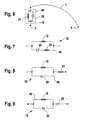
- the half-loop antenna known from the literature consists of a semicircular over a ground plane guided metallic conductor or antenna bracket, like this is shown by way of example in FIG. 5.
- the Mode of operation of the known half-loop antenna corresponds to that of a folding monopoly.
- their radiation diagram is in the vertical and the horizontal plane approximately that a monopoly, for example a ⁇ / 4 radiator.
- One on a resonance length of ⁇ / 2 half loop antenna has a height of 83% of a ⁇ / 4 radiator.
- a ⁇ / 2 Halfloop antenna has its maximum voltage on half Antenna length, i.e. in the highest point of the conductor bracket above the ground plane.
- An antenna unit is known from EP-0 684 661 which a substrate and an emitter mounted on the substrate whose radiating part is a flat plate, which is arranged parallel to the substrate.
- the radiant Part has a feed connection and an earth connection.
- GPS satellite-based vehicle navigation
- the GPS antenna preferably as a stripline antenna Cross radiation formed, consists of a plate a dielectric material on one side, as Ground surface, completely metallized and on the other Side, in the direction of radiation, with a partial Metallization is provided, and being the cellular antenna Has all-round characteristics in the horizontal radiation diagram and the large conductive area for this antenna as Ground reference surface is used.
- a half loop antenna according to the generic term of claim 1 is known from US 3,015,101.
- the invention is therefore based on the object Halfloop antenna to develop, especially in the automotive field can be used for mobile communications, whereby while maintaining good antenna characteristics compact and small-area design is achieved.
- a half loop antenna with a metallic antenna bracket, opposite one as a mass laid out basic level and the antenna bracket on on one side is connected to the basic level and on the other side has the antenna signal, the Antenna bracket formed by a surface, the outer edge of which forms a convex curve, i.e. is curved outwards, and wherein the area of the antenna bracket Ground plane sloping and parallel is arranged.
- the handling of the Antenna bracket the shape of a pointed at its ends tapering ellipse.
- the Antenna signal side of the antenna bracket an inductance inserted. Furthermore, the connection between the Antenna bracket and the base level by another Inductance take place.
- the flat antenna bracket preferably has on it On the outside a dielectric. Furthermore, the antenna be protected by a radome, the radome being Dielectric can be used.
- the inductance or inductances are preferred designed as a spring, the restoring force of the metallic Surface of the antenna bracket or parts thereof against the radome suppressed.
- the metallic antenna bracket can also be used as a metallic one Surface to be applied on the inside of the radome.
- the antenna area of the half-loop antenna can be used as Skelletantenne be realized, the area of the Antenna bracket through a thin metallic conductor is formed, the outer edge of the antenna area forms.
- the design of the Antenna bracket as a surface with a convex edge an increase the capacity of the antenna with the smallest footprint, whereby a broadband in the frequency band Radiation behavior is achieved. Furthermore, by the Increasing the antenna's own capacitance reduces the impedance at the Resonance or operating frequency to lower values, such as for example 50 ⁇ . advantageously, become neither the horizontal nor the vertical Radiation diagram influenced by the selected geometry or only influenced to a small extent. By increasing the There is the possibility of shortening the capacity mechanical length of the conductor bracket, so that at a corresponding shortening of the mechanical length of the Ladder bracket the height to 50% of a ⁇ / 4 radiator reduced.
- the feed network at least one has first resonance circuit which has an inductance and includes a capacity.
- the half-loop antenna signals in at least two frequency ranges radiate and / or receive.
- one Multi-band capable half-loop antenna realized at the same time is as compact and small-area as possible.
- the dining network comprises at least a first additional impedance, so is chosen that the impedance of the half-loop antenna to a predetermined impedance at the feed point is adapted. To this way you can fine tune the impedance of the Half loop antenna in the frequency bands used realize.
- Another advantage is that the dining network several resonance circuits different Has resonance frequency. This way you can do more realize as two frequency ranges in which the Halfloop antenna can send and / or receive signals at while maintaining their compact and small-area design.
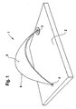
- Fig. 1 shows the first embodiment of the invention
- Half-loop antenna consisting of a flat metallic Antenna bracket 1, which is arranged above a base level 2 is, the antenna bracket 1 at point 3 its feed, i.e. the antenna signal, while the other side contacted the basic level 2 in point 4.
- the half-loop antenna thus acts as a folding monopoly.
- the surface 5 of the antenna bracket 1 the unwinding the shape of a pointed at its ends tapering ellipse. In general, this is the antenna area 5 bounding edge 6 a concave, i.e. domed, closed curve.
- This flat design causes an increase in the capacity of the antenna, so that a Broadband radiation behavior achieved in the frequency band becomes.
- the horizontal and vertical Radiation diagram of the flat in the present case curved geometry not or only to a small extent being affected.
- the one equipped with the flat geometry Antenna compared to the half-loop antennas known from the literature one to the sending source or to the receiver matched impedance, a higher bandwidth and a lower height with an unchanged radiation diagram on.
- the widening of the antenna geometry corresponds in its Effect of the head capacity with a ⁇ / 4 radiator.
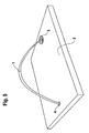
- FIG. 2 shows a further embodiment of the half loop antenna.
- an inductance 7 i.e. Extension coil
- the Extension coil 7 inserted at entry point 3.
- the surface 5 of the antenna bracket 1 runs essentially obliquely (viewed at earth point 4) to parallel (in the Figure viewed at the rear edge of the surface 6) Ground plane 1. Since the ⁇ / 2 half-loop antenna has its current maxima at the conductor bracket ends, i.e. at entry point 3 and at Has contact point 4 to the ground plate 2, so it unfolds there their greatest impact.
- Figure 3 shows a third embodiment of the Halloop antenna according to the invention, in which a further Extension coil 8 (inductance) in the antenna bracket 1 is inserted.
- the further extension coil 8 is on the the contacting with the base level 2 4 of the Antenna bracket 1 inserted and distributed the Total inductance on the two extension coils on the Ladder bracket ends, which gives you a spotlight that so is formed that it has a metallic surface 5 larger Expansion above the base level 2 (ground plate) with a has a certain distance from it.
- an antenna according to the above embodiments can optimize the effect of a radome as a dielectric be exploited.
- the goal is to keep the distance as low as possible between antenna and radome.
- the metallic surface of the antenna bracket directly on the radome see above can act through the effect of the radome as a dielectric Ironing area and thus overall length and width reduced further become.
- There is also an undefined detuning of the antenna prevented by a different distance of the Radome to the metallic surface of the conductor bracket due to Manufacturing tolerances can arise.
- Fig. 4 shows a further embodiment of the Halloop antenna according to the invention, in which the Head capacity is designed in the form of a skeletal antenna.
- the metallic surface 5 of the Antenna bracket 1 is through a thin metallic conductor 9 replaced, which represents the outer edge 6 of the surface 5.
- a skeletal antenna according to the fig shown second embodiment advantageously, with such an antenna there is the possibility of the half-loop antenna additional antennas, for example a GPS patch antenna.
- So-called two-band antennas are used in two-band operation used at two operating frequencies can send and / or receive electromagnetic waves. Such a two-band antenna shows in these two Operating frequencies each have a resonance.
- the feed network 10 between the Antenna bracket 1 and one of the antenna connections 3, 4 Feed network 10 is inserted, the feed network 10 at least one first resonance circuit 40; 50 has the one inductor 15; 16 and a capacity 20; 21 includes.
- the antenna connections 3, 4 are on the one hand Entry point 3 and on the other hand the contact point 4 to Ground level 2, which forms a reference potential.
- the feed network 10 is between the Antenna bracket 1 and the feed point 3 arranged. It could just as well be between the antenna bracket 1 and the contact point 4 to the basic level 2 be inserted.
- the feed network 10 as the first resonance circuit a first parallel resonance circuit 40.
- the first Parallel resonance circuit 40 provides a parallel connection a first inductance 15 and a first capacitance 20 represents
- the first inductance 15 brings about a first resonance frequency f r1 below the resonance frequency, which would be achieved if the antenna bracket 1 were used alone for the half-loop antenna, ie without the feed network 10.
- the first capacitance 20 brings about a second resonance frequency f r2 , which is greater than the first resonance frequency f r1 and is above the resonance frequency which would be achieved if the antenna bracket 1 were used alone for the half-loop antenna, ie without the feed network 10.
- the result is a two-band antenna which comprises a first frequency range with the first resonance frequency f r1 as the center frequency and a second frequency range with the second resonance frequency f r2 as the center frequency for transmitting and / or receiving signals
- the resonance frequency of the half-loop antenna at sole use of the antenna bracket 1, ie without the feed network 10 would lie between the two frequency ranges.
- the first inductance 15 and the first capacitance 20 must be dimensioned such that the resonance frequency of the first parallel resonance circuit 40 lies between the two realized frequency bands or between the two resonance frequencies f r1 , f r2 .
- the size of the antenna bracket 1 is reduced.
- the impedance of the feed network 10 makes sense to dimension the impedance of the feed network 10 such that, together with the impedance of the antenna bracket 1, it results in a predetermined impedance at the feed-in point 3 in both frequency ranges used for transmitting and / or receiving signals.
- an impedance specified for this contact point 4 must then be set accordingly by suitable dimensioning of the impedance of the feed network 10.
- the desired impedance at the feed point 3 or at the contact point 4 to the base plane 2 can be achieved by dimensioning the first inductance 15 and the first capacitance 20 accordingly, provided that the requirement is met that the resonance frequency of the first parallel resonance circuit 40 between the first resonance frequency f r1 and the second resonance frequency f r2 .
- the first inductance 15 and the first capacitance 20 cannot be dimensioned in such a way that the desired impedance is reached at the feed-in point 3 or at the contact point 4 with the base plane 2, it can also be provided according to the invention to arrange at least one first additional impedance in the feed network 10 , which is chosen so that the half-loop antenna is matched to the predetermined impedance at the antenna connection 3, 4 connected to the feed network 10.
- the at least one first additional impedance can be arranged in a circuit branch of the first parallel resonance circuit 40 or in series or parallel to the first parallel resonance circuit 40. According to FIG. 7, starting from the exemplary embodiment according to FIG.
- the first parallel resonance circuit 40 is expanded, for example, in such a way that a matching inductor 25 is connected in series to the first capacitance 20, which is dimensioned such that the predetermined impedance is set at the feed-in point 3.
- a matching inductor 25 can also be connected in series with the first parallel resonance circuit 40 in order to achieve the desired adaptation to the impedance at the feed point 3 according to FIG. 6.
- an appropriately dimensioned matching capacitor 26 can also be used for impedance matching, which in the example according to FIG. 9 is connected in series with the parallel resonance circuit 40, but could also be connected in series with the first inductance 15 in the parallel resonance circuit 40.
- the dining network 10, which in the example according to FIG first parallel resonance circuit 40 with the first inductance 15 and the first capacitance 20 comprises a simple and inexpensive solution for the realization of a half loop antenna represents that in two different frequency ranges Can send and / or receive signals.
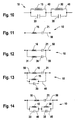
- the feed network 10 can also be used as Series resonance circuit be formed, as in Figure 11 based of a first series resonant circuit 50 is shown.
- the first series resonant circuit 50 comprises a second one Inductor 16, which is in series with a second capacitance 21 is switched.
- a vote or fine-tuning of the Impedance of the first series resonant circuit 50 to achieve the predetermined impedance of the half-loop antenna on Entry point 3 or at contact point 4 to base level 2 can now start from the first series resonant circuit 50 be achieved, one or more accordingly dimensioned additional impedances in the feed network 10 insert.
- This can be done, for example, by Parallel connection of another capacity to the second Inductance 16 or to the entire first series resonance circuit 50 happen. Accordingly, this can also be done by the second capacitance 21 or the entire first Series resonant circuit 50 a further inductance in parallel turn.
- the feed network 10 for example a parallel connection of two Series resonant circuits 50, 55 comprise, as in FIG. 12 shown.
- the first Series resonance circuit 50, a second series resonance circuit 55 connected in parallel, the second series resonant circuit 55 from a fourth inductor 31 and one in series switched fourth capacitance 36 is formed.
- the dining network 10 two connected in series Parallel resonance circuits 40, 45 includes.
- Parallel resonance circuit 45 connected in series, one Parallel connection from a third inductor 30 and a third capacitance 35 forms.
- Figure 13 is as another example a parallel connection of the first Parallel resonance circuit 40 with the first Series resonance circuit 50 shown, these Parallel connection forms the feed network 10.
- a Three-band half-loop antenna by connecting a series Parallel resonance circuit with a series resonance circuit achieve.
- three frequency ranges can be realize in which the half-loop antenna send signals and / or can receive.
- the inductors and Capacities of the two respective resonance circuits dimension that the resonance frequencies of each Resonance circuits between those for transmission and / or Receive usable frequency ranges of the half-loop antenna lie.
- Even more frequency bands for sending and / or receiving with the half loop antenna can be used by using further Achieve resonance circuits. So could more than two Parallel resonance circuits in series or more than two Series resonance circuits are connected in parallel. Can too several series and parallel resonance circuits to each other in Can be connected in series or in parallel, towards it make sure that there are not two series resonance circuits to each other be connected in series and that not two Parallel resonance circuits connected in parallel to each other become.
- the resonance circuits are each so closed dimension that their resonance frequencies between the individual for sending and / or receiving signals used frequency ranges of the half loop antenna are and differ from each other.
- Figure 14 shows an example a parallel connection of the first series resonant circuit 50 with a series connection of the first parallel resonance circuit 40 and the second parallel resonance circuit 45 the first series resonant circuit 50, for example, also one Series connection from more than two parallel resonance circuits or a series connection of several Parallel resonance circuits and a series resonance circuit be connected in parallel.
- Fine-tuning the impedance matching in such Half loop antennas with more than two frequency ranges for Sending and / or receiving signals takes place in the described way by appropriate insertion additional impedances, as shown in Figure 7, Figure 8 and Figure 9 has been described.
- additional impedances can be used. These can be like described in one or more circuit branches of a each resonance circuit of the feed network 10 or in series or be arranged in parallel.
- the antennas according to the preferred embodiments have both in the side view and in the top view tapered profile, which is aerodynamically favorable Has properties.
- Has properties When using two Extension coils whose inductance is asymmetrical distributed, you can see the slope angle of the side profile determine or change the shape of the profile itself. In order to is both a straight ascending and one with a Curvature increasing profile can be realized.
- the antenna is suitable for good aerodynamic properties also as an on-glass antenna, since it is installed at the Upper edge of the front or rear window due to its wedge-shaped Forming forms a smooth transition to the body.
- the area of application of the flat antennas described above is among other things, when sending and receiving signals in the GSM band.
- a rod antenna for radio reception in which another antenna for sending and receiving signals could be integrated in the GSM band, does not exist or stands not available, for example because it is in the form of a Rear window antenna was realized, there is Possibility to separate such a GSM antenna to install.
- Such flat antennas are preferred installed where antennas in the vehicle geometry should be integrated.
- radiation can the occupant with an omnidirectional antenna be minimized if these are in an installation position located on or directly on the vehicle roof.
- the antenna By dimensioning the antenna accordingly these also for vertically polarized transmission or reception electromagnetic waves in other frequency bands, for example in the e-network.
Landscapes
- Details Of Aerials (AREA)
- Variable-Direction Aerials And Aerial Arrays (AREA)
Claims (23)
- Antenne demi-cadre comportant un étrier d'antenne métallique (1), monté sur un plan de base (2) constituant la masse et relié d'un côté (4) au plan de base (2) et de l'autre côté (3) au signal d'antenne, cet étrier (1) comprenant une surface (5) métallique en particulier, dont le bord externe (6) forme une courbe convexe, c'est-à-dire bombé vers l'extérieur,
caractérisée en ce que
la surface (5) de l'étrier comprend par rapport au plan de base (2), une partie oblique suivie d'une partie parallèle. - Antenne demi-cadre selon la revendication 1,
caractérisée en ce que
la surface (5) de l'étrier d'antenne est bombée vers l'extérieur par rapport au plan de base. - Antenne demi-cadre selon l'une quelconque des revendications 1 ou 2,
caractérisée en ce que
développé, l'étrier d'antenne (1) a la forme d'une ellipse dont les extrémités sont en pointe. - Antenne demi-cadre selon l'une quelconque des revendications précédentes
caractérisée en ce que
sur le côté du signal d'antenne (3) de l'étrier d'antenne (1) est montée une inductance (7). - Antenne demi-cadre selon la revendication 4,
caractérisée en ce que
la liaison entre l'étrier d'antenne (1) et le plan de base (2) est assurée par une deuxième inductance (8). - Antenne demi-cadre selon l'une quelconque des revendications précédentes
caractérisée en ce que
l'antenne présente un radôme. - Antenne demi-cadre selon l'une quelconque des revendications 4 et 6 ou 5 et 6,
caractérisée en ce que
l'inductance (7) ou les inductances (7, 8) ont la forme de ressorts dont la force de rappel pousse la surface métallique (5) de l'étrie (1) ou des parties de cette surface contre le radôme. - Antenne demi-cadre selon l'une quelconque des revendications 6 ou 7,
caractérisée en ce que
le radôme agit comme un diélectrique. - Antenne demi-cadre selon l'une quelconque des revendications 6, 7 ou 8,
caractérisée en ce que
la surface métallique (5) de rétrier d'antenne (5) est réalisée sur la face interne du radôme. - Antenne demi-cadre selon l'une quelconque des revendications précédentes,
caractérisée en ce que
la nappe (5) de l'étrier d'antenne (1) porte sur sa face externe un diélectrique. - Antenne demi-cadre selon l'une quelconque des revendications précédentes,
caractérisée en ce que
l'antenne est une antenne squelette dont la surface (5) est entourée par un conducteur métallique mince (9) formant le bord externe (6) de la surface (5). - Antenne demi-cadre selon l'une quelconque des revendications précédentes,
caractérisée en ce qu'
entre l'étrier d'antenne (1) et un des raccords d'antenne (3, 4) est monté un réseau d'alimentation (10) présentant au moins un premier circuit résonant (40 ; 50) comprenant une inductance (15, 16) et une capacité (20, 21). - Antenne demi-cadre selon la revendication 12,
caractérisée en ce que
le premier circuit résonant (40) est un circuit parallèle. - Antenne demi-cadre selon la revendication 12,
caractérisée en ce que
le premier circuit résonant (50) est un circuit série. - Antenne demi-cadre selon l'une quelconque des revendications 12, 13 et 14,
caractérisée en ce que
le réseau d'alimentation (10) est raccordé à un point d'alimentation (3). - Antenne demi-cadre selon l'une quelconque des revendications 12 à 15,
caractérisée en ce que
le circuit d'alimentation (10) est relié au plan de base (2). - Antenne demi-cadre selon l'une quelconque des revendications 12 à 16,
caractérisée en ce que
le circuit d'alimentation (10) comprend au moins une première impédance supplémentaire (25, 26) qui est choisie de manière à ajuster le réseau (10) sur une impédance prédéterminée au raccord d'antenne (3, 4) reliant celle-ci au réseau d'alimentation (10). - Antenne demi-cadre selon la revendication 17,
caractérisée en ce que
la première impédance supplémentaire (25, 26) est montée dans une branche du premier circuit résonant (40, 50) ou en série ou en parallèle avec au moins un premier circuit résonant (40, 50). - Antenne demi-cadre selon l'une quelconque des revendications 12 à 18,
caractérisée en ce que
le réseau d'alimentation (10) comprend plusieurs circuits résonants (40, 45, 50, 55) ayant des fréquences de résonance différentes. - Antenne demi-cadre selon la revendication 19,
caractérisée en ce que
deux circuits résonants parallèles (40, 45) sont reliés en série. - Antenne demi-cadre selon l'une quelconque des revendications 19 ou 20,
caractérisée en ce que
deux circuits résonants série (50, 55) sont reliés en parallèle. - Antenne demi-cadre selon l'une quelconque des revendications 19, 20 ou 21,
caractérisée en ce qu'
un circuit résonant série (50, 55) et un circuit résonant parallèle (40, 45) sont montés en parallèle ou en série. - Antenne demi-cadre selon l'une quelconque des revendications 19 à 22,
caractérisée en ce qu'
un circuit résonant série (50, 55) est monté en parallèle avec un circuit constitué de plusieurs circuits résonants parallèles (40, 45) reliés en série.
Applications Claiming Priority (3)
| Application Number | Priority Date | Filing Date | Title |
|---|---|---|---|
| DE19857191 | 1998-12-11 | ||
| DE19857191A DE19857191A1 (de) | 1998-12-11 | 1998-12-11 | Halfloop-Antenne |
| PCT/DE1999/003966 WO2000036703A1 (fr) | 1998-12-11 | 1999-12-10 | Demi-cadre |
Publications (2)
| Publication Number | Publication Date |
|---|---|
| EP1138097A1 EP1138097A1 (fr) | 2001-10-04 |
| EP1138097B1 true EP1138097B1 (fr) | 2003-02-05 |
Family
ID=7890743
Family Applications (1)
| Application Number | Title | Priority Date | Filing Date |
|---|---|---|---|
| EP99964435A Expired - Lifetime EP1138097B1 (fr) | 1998-12-11 | 1999-12-10 | Demi-cadre |
Country Status (6)
| Country | Link |
|---|---|
| US (1) | US6590541B1 (fr) |
| EP (1) | EP1138097B1 (fr) |
| JP (1) | JP4414599B2 (fr) |
| KR (1) | KR100724300B1 (fr) |
| DE (2) | DE19857191A1 (fr) |
| WO (1) | WO2000036703A1 (fr) |
Families Citing this family (91)
| Publication number | Priority date | Publication date | Assignee | Title |
|---|---|---|---|---|
| US7609222B2 (en) * | 2007-12-05 | 2009-10-27 | Antennas Direct, Inc. | Antenna assemblies with antenna elements and reflectors |
| US10957979B2 (en) | 2018-12-06 | 2021-03-23 | Antennas Direct, Inc. | Antenna assemblies |
| USD881172S1 (en) | 1975-11-03 | 2020-04-14 | Antennas Direct, Inc. | Antenna and base stand |
| USD868045S1 (en) | 2008-02-29 | 2019-11-26 | Antennas Direct, Inc. | Antenna |
| USD809490S1 (en) | 2008-02-29 | 2018-02-06 | Antennas Direct, Inc. | Antenna |
| USD867347S1 (en) | 2008-02-29 | 2019-11-19 | Antennas Direct, Inc. | Antenna |
| US20140292597A1 (en) | 2007-12-05 | 2014-10-02 | Antennas Direct, Inc. | Antenna assemblies with tapered loop antenna elements |
| USD666178S1 (en) | 2008-02-29 | 2012-08-28 | Antennas Direct, Inc. | Antenna |
| US8368607B2 (en) * | 2007-12-05 | 2013-02-05 | Antennas Direct, Inc. | Antenna assemblies with antenna elements and reflectors |
| US7865154B2 (en) * | 2000-07-20 | 2011-01-04 | Paratek Microwave, Inc. | Tunable microwave devices with auto-adjusting matching circuit |
| US8744384B2 (en) | 2000-07-20 | 2014-06-03 | Blackberry Limited | Tunable microwave devices with auto-adjusting matching circuit |
| US8064188B2 (en) | 2000-07-20 | 2011-11-22 | Paratek Microwave, Inc. | Optimized thin film capacitors |
| WO2002009226A1 (fr) | 2000-07-20 | 2002-01-31 | Paratek Microwave, Inc. | Dispositifs micro-ondes accordables a circuit d'adaptation auto-ajustable |
| DE10045634B4 (de) * | 2000-09-15 | 2005-08-25 | Hella Kgaa Hueck & Co. | Resonante Antenne für eine Steuereinrichtung für ein Kraftfahrzeug und deren Verwendung |
| WO2003067707A1 (fr) * | 2002-01-03 | 2003-08-14 | Time Domain Corporation | Antenne cadre a large bande |
| US6876334B2 (en) * | 2003-02-28 | 2005-04-05 | Hong Kong Applied Science And Technology Research Institute Co., Ltd. | Wideband shorted tapered strip antenna |
| CN1765030B (zh) * | 2003-04-28 | 2010-05-26 | 胡贝尔和茹纳股份公司 | 宽带天线装置 |
| US7592958B2 (en) * | 2003-10-22 | 2009-09-22 | Sony Ericsson Mobile Communications, Ab | Multi-band antennas and radio apparatus incorporating the same |
| US7515881B2 (en) * | 2003-11-26 | 2009-04-07 | Starkey Laboratories, Inc. | Resonance frequency shift canceling in wireless hearing aids |
| US7710335B2 (en) * | 2004-05-19 | 2010-05-04 | Delphi Technologies, Inc. | Dual band loop antenna |
| DE102004054015A1 (de) * | 2004-11-09 | 2006-05-11 | Robert Bosch Gmbh | Planare Breitbandantenne |
| KR100724133B1 (ko) * | 2005-10-11 | 2007-06-04 | 삼성전자주식회사 | 원격 모니터링을 위한 소형 액세서리 |
| US9406444B2 (en) | 2005-11-14 | 2016-08-02 | Blackberry Limited | Thin film capacitors |
| US7711337B2 (en) | 2006-01-14 | 2010-05-04 | Paratek Microwave, Inc. | Adaptive impedance matching module (AIMM) control architectures |
| US8325097B2 (en) | 2006-01-14 | 2012-12-04 | Research In Motion Rf, Inc. | Adaptively tunable antennas and method of operation therefore |
| US8125399B2 (en) * | 2006-01-14 | 2012-02-28 | Paratek Microwave, Inc. | Adaptively tunable antennas incorporating an external probe to monitor radiated power |
| US7714676B2 (en) | 2006-11-08 | 2010-05-11 | Paratek Microwave, Inc. | Adaptive impedance matching apparatus, system and method |
| US7535312B2 (en) | 2006-11-08 | 2009-05-19 | Paratek Microwave, Inc. | Adaptive impedance matching apparatus, system and method with improved dynamic range |
| US8299867B2 (en) | 2006-11-08 | 2012-10-30 | Research In Motion Rf, Inc. | Adaptive impedance matching module |
| US7813777B2 (en) * | 2006-12-12 | 2010-10-12 | Paratek Microwave, Inc. | Antenna tuner with zero volts impedance fold back |
| US7917104B2 (en) | 2007-04-23 | 2011-03-29 | Paratek Microwave, Inc. | Techniques for improved adaptive impedance matching |
| US8213886B2 (en) | 2007-05-07 | 2012-07-03 | Paratek Microwave, Inc. | Hybrid techniques for antenna retuning utilizing transmit and receive power information |
| DE202007010239U1 (de) * | 2007-07-24 | 2007-09-20 | Rosenberger Hochfrequenztechnik Gmbh & Co. Kg | Schleifenrichtkoppler |
| US7991363B2 (en) | 2007-11-14 | 2011-08-02 | Paratek Microwave, Inc. | Tuning matching circuits for transmitter and receiver bands as a function of transmitter metrics |
| US7990335B2 (en) * | 2007-12-05 | 2011-08-02 | Antennas Direct, Inc. | Antenna assemblies with antenna elements and reflectors |
| US11929562B2 (en) | 2007-12-05 | 2024-03-12 | Antennas Direct, Inc. | Antenna assemblies with tapered loop antenna elements |
| US7639201B2 (en) * | 2008-01-17 | 2009-12-29 | University Of Massachusetts | Ultra wideband loop antenna |
| US20090210035A1 (en) * | 2008-02-20 | 2009-08-20 | Daniel Gelbart | System for powering medical implants |
| USD920962S1 (en) | 2008-02-29 | 2021-06-01 | Antennas Direct, Inc. | Base stand for antenna |
| USD815073S1 (en) | 2008-02-29 | 2018-04-10 | Antennas Direct, Inc. | Antenna |
| USD804459S1 (en) | 2008-02-29 | 2017-12-05 | Antennas Direct, Inc. | Antennas |
| USD883265S1 (en) | 2008-02-29 | 2020-05-05 | Antennas Direct, Inc. | Antenna |
| USD883264S1 (en) | 2008-02-29 | 2020-05-05 | Antennas Direct, Inc. | Antenna |
| US8072285B2 (en) | 2008-09-24 | 2011-12-06 | Paratek Microwave, Inc. | Methods for tuning an adaptive impedance matching network with a look-up table |
| US8067858B2 (en) * | 2008-10-14 | 2011-11-29 | Paratek Microwave, Inc. | Low-distortion voltage variable capacitor assemblies |
| US8164529B2 (en) | 2008-10-20 | 2012-04-24 | Harris Corporation | Loop antenna including impedance tuning gap and associated methods |
| US20100201578A1 (en) * | 2009-02-12 | 2010-08-12 | Harris Corporation | Half-loop chip antenna and associated methods |
| US8472888B2 (en) | 2009-08-25 | 2013-06-25 | Research In Motion Rf, Inc. | Method and apparatus for calibrating a communication device |
| JP5687421B2 (ja) * | 2009-10-01 | 2015-03-18 | 小島プレス工業株式会社 | 車両用アンテナエレメントおよび車両用アンテナ |
| US9026062B2 (en) | 2009-10-10 | 2015-05-05 | Blackberry Limited | Method and apparatus for managing operations of a communication device |
| US8576125B2 (en) * | 2009-10-30 | 2013-11-05 | Digi International Inc. | Planar wideband antenna |
| US8803631B2 (en) | 2010-03-22 | 2014-08-12 | Blackberry Limited | Method and apparatus for adapting a variable impedance network |
| WO2011133657A2 (fr) | 2010-04-20 | 2011-10-27 | Paratek Microwave, Inc. | Procédé et appareil permettant de gérer l'interférence dans un dispositif de communication |
| US9070969B2 (en) * | 2010-07-06 | 2015-06-30 | Apple Inc. | Tunable antenna systems |
| US9379454B2 (en) | 2010-11-08 | 2016-06-28 | Blackberry Limited | Method and apparatus for tuning antennas in a communication device |
| US8712340B2 (en) | 2011-02-18 | 2014-04-29 | Blackberry Limited | Method and apparatus for radio antenna frequency tuning |
| US8655286B2 (en) | 2011-02-25 | 2014-02-18 | Blackberry Limited | Method and apparatus for tuning a communication device |
| US8626083B2 (en) | 2011-05-16 | 2014-01-07 | Blackberry Limited | Method and apparatus for tuning a communication device |
| US8594584B2 (en) | 2011-05-16 | 2013-11-26 | Blackberry Limited | Method and apparatus for tuning a communication device |
| US9769826B2 (en) | 2011-08-05 | 2017-09-19 | Blackberry Limited | Method and apparatus for band tuning in a communication device |
| US20130214979A1 (en) * | 2012-02-17 | 2013-08-22 | Emily B. McMilin | Electronic Device Antennas with Filter and Tuning Circuitry |
| US8948889B2 (en) | 2012-06-01 | 2015-02-03 | Blackberry Limited | Methods and apparatus for tuning circuit components of a communication device |
| US9806420B2 (en) * | 2012-06-12 | 2017-10-31 | The United States Of America As Represented By Secretary Of The Navy | Near field tunable parasitic antenna |
| US9853363B2 (en) | 2012-07-06 | 2017-12-26 | Blackberry Limited | Methods and apparatus to control mutual coupling between antennas |
| US9246223B2 (en) | 2012-07-17 | 2016-01-26 | Blackberry Limited | Antenna tuning for multiband operation |
| US9413066B2 (en) | 2012-07-19 | 2016-08-09 | Blackberry Limited | Method and apparatus for beam forming and antenna tuning in a communication device |
| US9350405B2 (en) | 2012-07-19 | 2016-05-24 | Blackberry Limited | Method and apparatus for antenna tuning and power consumption management in a communication device |
| US9362891B2 (en) | 2012-07-26 | 2016-06-07 | Blackberry Limited | Methods and apparatus for tuning a communication device |
| US8963795B1 (en) * | 2012-10-15 | 2015-02-24 | L-3 Communications Corp. | Wedge shaped scimitar antenna |
| EP2907196A4 (fr) * | 2012-10-15 | 2016-06-08 | Gapwaves Ab | Agencement d'une antenne à mise à terre automatique |
| JP6030434B2 (ja) * | 2012-12-17 | 2016-11-24 | Necプラットフォームズ株式会社 | アンテナ装置 |
| US9374113B2 (en) | 2012-12-21 | 2016-06-21 | Blackberry Limited | Method and apparatus for adjusting the timing of radio antenna tuning |
| US10404295B2 (en) | 2012-12-21 | 2019-09-03 | Blackberry Limited | Method and apparatus for adjusting the timing of radio antenna tuning |
| CN103746168A (zh) * | 2013-12-27 | 2014-04-23 | 青岛中科软件股份有限公司 | 板载PCB天线的325MHz射频模块 |
| CN103746166B (zh) * | 2013-12-27 | 2016-06-08 | 青岛中科软件股份有限公司 | 板载PCB天线的928MHz射频模块 |
| CN103746175B (zh) * | 2013-12-27 | 2016-06-08 | 青岛中科软件股份有限公司 | 板载PCB天线的2450MHz射频模块 |
| US9438319B2 (en) | 2014-12-16 | 2016-09-06 | Blackberry Limited | Method and apparatus for antenna selection |
| USD781825S1 (en) | 2015-07-29 | 2017-03-21 | Voxx International Corporation | Antenna stand |
| US10224592B2 (en) | 2015-07-29 | 2019-03-05 | Voxx International Corporation | Stand for planar antenna |
| US10128575B2 (en) | 2015-09-02 | 2018-11-13 | Antennas Direct, Inc. | HDTV antenna assemblies |
| USD824884S1 (en) | 2015-10-08 | 2018-08-07 | Antennas Direct, Inc. | Antenna element |
| US9761935B2 (en) | 2015-09-02 | 2017-09-12 | Antennas Direct, Inc. | HDTV antenna assemblies |
| USD827620S1 (en) | 2015-10-08 | 2018-09-04 | Antennas Direct, Inc. | Antenna element |
| USD811752S1 (en) | 2015-10-08 | 2018-03-06 | Antennas Direct, Inc. | Picture frame antenna |
| EP3378123A4 (fr) * | 2015-11-17 | 2019-06-19 | Gapwaves AB | Agencement d'antenne en noeud papillon montable en surface automatiquement mis à la terre, pétale d'antenne et procédé de fabrication |
| USD781826S1 (en) | 2015-12-28 | 2017-03-21 | Voxx International Corporation | Antenna stand |
| DE102018218891B4 (de) | 2018-11-06 | 2023-12-07 | Fraunhofer-Gesellschaft zur Förderung der angewandten Forschung e.V. | Dreidimensionale Schleifen-Antennenvorrichtung |
| US11791558B2 (en) * | 2021-08-23 | 2023-10-17 | GM Global Technology Operations LLC | Simple ultra wide band very low profile antenna |
| US12548912B2 (en) | 2022-07-01 | 2026-02-10 | Kabushiki Kaisha Tokai Rika Denki Seisakusho | Metal plate antenna and antenna device |
| JP2025101848A (ja) * | 2023-12-26 | 2025-07-08 | Necプラットフォームズ株式会社 | 小型広帯域アンテナ |
| CN121035605A (zh) * | 2025-10-31 | 2025-11-28 | 广州慧智微电子股份有限公司 | 一种片上天线 |
Citations (1)
| Publication number | Priority date | Publication date | Assignee | Title |
|---|---|---|---|---|
| US3015101A (en) * | 1958-10-31 | 1961-12-26 | Edwin M Turner | Scimitar antenna |
Family Cites Families (14)
| Publication number | Priority date | Publication date | Assignee | Title |
|---|---|---|---|---|
| US3618104A (en) * | 1968-02-26 | 1971-11-02 | Multronics Inc | Broadband cornucopia-type antenna system |
| US3906507A (en) * | 1974-03-27 | 1975-09-16 | Lockheed Aircraft Corp | Combination glideslope/localizer antenna for aircraft |
| HU181154B (en) * | 1980-07-18 | 1983-06-28 | Epitestudomanyi Intezet | Shaped building unit and space limiting or dividing structure made of same as well as method for producing the shaped building unit |
| US4433336A (en) * | 1982-02-05 | 1984-02-21 | The United States Of America As Represented By The Secretary Of Commerce | Three-element antenna formed of orthogonal loops mounted on a monopole |
| JP2870940B2 (ja) * | 1990-03-01 | 1999-03-17 | 株式会社豊田中央研究所 | 車載アンテナ |
| US5294938A (en) * | 1991-03-15 | 1994-03-15 | Matsushita Electric Works, Ltd. | Concealedly mounted top loaded vehicular antenna unit |
| US5521610A (en) | 1993-09-17 | 1996-05-28 | Trimble Navigation Limited | Curved dipole antenna with center-post amplifier |
| DE69422022T2 (de) | 1994-05-10 | 2000-08-03 | Murata Mfg. Co., Ltd. | Antenneneinheit |
| DE19514556A1 (de) | 1995-04-20 | 1996-10-24 | Fuba Automotive Gmbh | Flachantennen-Anordnung |
| US5592182A (en) * | 1995-07-10 | 1997-01-07 | Texas Instruments Incorporated | Efficient, dual-polarization, three-dimensionally omni-directional crossed-loop antenna with a planar base element |
| US5654724A (en) * | 1995-08-07 | 1997-08-05 | Datron/Transco Inc. | Antenna providing hemispherical omnidirectional coverage |
| US5784032A (en) * | 1995-11-01 | 1998-07-21 | Telecommunications Research Laboratories | Compact diversity antenna with weak back near fields |
| JP2957463B2 (ja) | 1996-03-11 | 1999-10-04 | 日本電気株式会社 | パッチアンテナおよびその製造方法 |
| US6111549A (en) * | 1997-03-27 | 2000-08-29 | Satloc, Inc. | Flexible circuit antenna and method of manufacture thereof |
-
1998
- 1998-12-11 DE DE19857191A patent/DE19857191A1/de not_active Ceased
-
1999
- 1999-12-10 EP EP99964435A patent/EP1138097B1/fr not_active Expired - Lifetime
- 1999-12-10 WO PCT/DE1999/003966 patent/WO2000036703A1/fr not_active Ceased
- 1999-12-10 KR KR1020017007157A patent/KR100724300B1/ko not_active Expired - Fee Related
- 1999-12-10 US US09/857,930 patent/US6590541B1/en not_active Expired - Fee Related
- 1999-12-10 DE DE59904250T patent/DE59904250D1/de not_active Expired - Lifetime
- 1999-12-10 JP JP2000588855A patent/JP4414599B2/ja not_active Expired - Fee Related
Patent Citations (1)
| Publication number | Priority date | Publication date | Assignee | Title |
|---|---|---|---|---|
| US3015101A (en) * | 1958-10-31 | 1961-12-26 | Edwin M Turner | Scimitar antenna |
Also Published As
| Publication number | Publication date |
|---|---|
| DE59904250D1 (de) | 2003-03-13 |
| JP4414599B2 (ja) | 2010-02-10 |
| KR100724300B1 (ko) | 2007-06-04 |
| JP2002533002A (ja) | 2002-10-02 |
| KR20010081072A (ko) | 2001-08-25 |
| EP1138097A1 (fr) | 2001-10-04 |
| US6590541B1 (en) | 2003-07-08 |
| DE19857191A1 (de) | 2000-07-06 |
| WO2000036703A1 (fr) | 2000-06-22 |
Similar Documents
| Publication | Publication Date | Title |
|---|---|---|
| EP1138097B1 (fr) | Demi-cadre | |
| DE60102052T2 (de) | Doppeltwirkende Antenne | |
| DE60225513T2 (de) | Mehrfrequenzantenne | |
| DE60023062T2 (de) | Antennenkonstruktion | |
| DE69617947T2 (de) | Gedruckte mehrband monopolantenne | |
| DE60211316T2 (de) | Antennenanordnung | |
| DE60019196T2 (de) | Antennenstruktur | |
| DE69317235T2 (de) | Wenig Raum beanspruchende, breitbandige Antenne mit zugehörigem Sendeempfänger | |
| DE60306513T2 (de) | Antennenanordnung | |
| DE69624300T2 (de) | Antenne | |
| DE69835246T2 (de) | Doppelresonanzantennenstruktur für mehrere Frequenzbereiche | |
| DE602004002413T2 (de) | Mehrband-Planarantenne | |
| EP1154518B1 (fr) | Antenne intégrée pour téléphones portables | |
| EP0841715B1 (fr) | Antenne plate | |
| DE69015026T2 (de) | Breitbandige Antenne für bewegliche Funktelefonverbindungen. | |
| DE69913962T2 (de) | Mehrband-fahrzeugantenne | |
| EP2693565B1 (fr) | Emetteur électrique pour signaux radio polarisés verticalement | |
| DE3486135T2 (de) | Antenne fuer den mobilen telefonverkehr. | |
| DE2136759C2 (de) | Antenne mit metallischem Rahmen und den Rahmen erregendem Unipol | |
| EP1297590A1 (fr) | Antenne fendue | |
| DE4443596B4 (de) | Funkantenne auf der Fensterscheibe eines Kraftfahrzeugs | |
| DE102014016851B3 (de) | MIMO Schlitzantenne für Kraftfahrzeuge | |
| WO2004102742A1 (fr) | Antenne multibande | |
| DE102007055234A1 (de) | Mehrbandiges Empfangsantennenmodul | |
| WO2004082072A1 (fr) | Antenne multibande a capacite terminale |
Legal Events
| Date | Code | Title | Description |
|---|---|---|---|
| PUAI | Public reference made under article 153(3) epc to a published international application that has entered the european phase |
Free format text: ORIGINAL CODE: 0009012 |
|
| 17P | Request for examination filed |
Effective date: 20010711 |
|
| AK | Designated contracting states |
Kind code of ref document: A1 Designated state(s): AT BE CH CY DE DK ES FI FR GB GR IE IT LI LU MC NL PT SE |
|
| GRAG | Despatch of communication of intention to grant |
Free format text: ORIGINAL CODE: EPIDOS AGRA |
|
| 17Q | First examination report despatched |
Effective date: 20020508 |
|
| GRAG | Despatch of communication of intention to grant |
Free format text: ORIGINAL CODE: EPIDOS AGRA |
|
| GRAH | Despatch of communication of intention to grant a patent |
Free format text: ORIGINAL CODE: EPIDOS IGRA |
|
| GRAH | Despatch of communication of intention to grant a patent |
Free format text: ORIGINAL CODE: EPIDOS IGRA |
|
| GRAA | (expected) grant |
Free format text: ORIGINAL CODE: 0009210 |
|
| AK | Designated contracting states |
Designated state(s): DE FR GB IT SE |
|
| REG | Reference to a national code |
Ref country code: GB Ref legal event code: FG4D Free format text: NOT ENGLISH |
|
| REF | Corresponds to: |
Ref document number: 59904250 Country of ref document: DE Date of ref document: 20030313 Kind code of ref document: P |
|
| REG | Reference to a national code |
Ref country code: SE Ref legal event code: TRGR |
|
| GBT | Gb: translation of ep patent filed (gb section 77(6)(a)/1977) |
Effective date: 20030513 |
|
| ET | Fr: translation filed | ||
| PLBE | No opposition filed within time limit |
Free format text: ORIGINAL CODE: 0009261 |
|
| STAA | Information on the status of an ep patent application or granted ep patent |
Free format text: STATUS: NO OPPOSITION FILED WITHIN TIME LIMIT |
|
| 26N | No opposition filed |
Effective date: 20031106 |
|
| PGFP | Annual fee paid to national office [announced via postgrant information from national office to epo] |
Ref country code: IT Payment date: 20081223 Year of fee payment: 10 Ref country code: SE Payment date: 20081222 Year of fee payment: 10 |
|
| EUG | Se: european patent has lapsed | ||
| PGFP | Annual fee paid to national office [announced via postgrant information from national office to epo] |
Ref country code: FR Payment date: 20110107 Year of fee payment: 12 |
|
| REG | Reference to a national code |
Ref country code: GB Ref legal event code: 732E Free format text: REGISTERED BETWEEN 20110127 AND 20110202 |
|
| REG | Reference to a national code |
Ref country code: FR Ref legal event code: TP |
|
| PG25 | Lapsed in a contracting state [announced via postgrant information from national office to epo] |
Ref country code: IT Free format text: LAPSE BECAUSE OF NON-PAYMENT OF DUE FEES Effective date: 20091210 |
|
| PGFP | Annual fee paid to national office [announced via postgrant information from national office to epo] |
Ref country code: GB Payment date: 20101221 Year of fee payment: 12 |
|
| REG | Reference to a national code |
Ref country code: DE Ref legal event code: R081 Ref document number: 59904250 Country of ref document: DE Owner name: BLAUPUNKT ANTENNA SYSTEMS GMBH & CO. KG, DE Free format text: FORMER OWNER: ROBERT BOSCH GMBH, 70469 STUTTGART, DE Effective date: 20110315 |
|
| PG25 | Lapsed in a contracting state [announced via postgrant information from national office to epo] |
Ref country code: SE Free format text: LAPSE BECAUSE OF NON-PAYMENT OF DUE FEES Effective date: 20091211 |
|
| PGFP | Annual fee paid to national office [announced via postgrant information from national office to epo] |
Ref country code: DE Payment date: 20110218 Year of fee payment: 12 |
|
| GBPC | Gb: european patent ceased through non-payment of renewal fee |
Effective date: 20111210 |
|
| REG | Reference to a national code |
Ref country code: FR Ref legal event code: ST Effective date: 20120831 |
|
| REG | Reference to a national code |
Ref country code: DE Ref legal event code: R119 Ref document number: 59904250 Country of ref document: DE Effective date: 20120703 |
|
| PG25 | Lapsed in a contracting state [announced via postgrant information from national office to epo] |
Ref country code: DE Free format text: LAPSE BECAUSE OF NON-PAYMENT OF DUE FEES Effective date: 20120703 Ref country code: GB Free format text: LAPSE BECAUSE OF NON-PAYMENT OF DUE FEES Effective date: 20111210 |
|
| PG25 | Lapsed in a contracting state [announced via postgrant information from national office to epo] |
Ref country code: FR Free format text: LAPSE BECAUSE OF NON-PAYMENT OF DUE FEES Effective date: 20120102 |