EP1138200A2 - Fahrbare Vorrichtung zum Ausbringen einer Flüssigkeit - Google Patents
Fahrbare Vorrichtung zum Ausbringen einer Flüssigkeit Download PDFInfo
- Publication number
- EP1138200A2 EP1138200A2 EP01106776A EP01106776A EP1138200A2 EP 1138200 A2 EP1138200 A2 EP 1138200A2 EP 01106776 A EP01106776 A EP 01106776A EP 01106776 A EP01106776 A EP 01106776A EP 1138200 A2 EP1138200 A2 EP 1138200A2
- Authority
- EP
- European Patent Office
- Prior art keywords
- holding element
- mast
- receiving space
- cross arm
- transport position
- Prior art date
- Legal status (The legal status is an assumption and is not a legal conclusion. Google has not performed a legal analysis and makes no representation as to the accuracy of the status listed.)
- Granted
Links
Images







Classifications
-
- A—HUMAN NECESSITIES
- A01—AGRICULTURE; FORESTRY; ANIMAL HUSBANDRY; HUNTING; TRAPPING; FISHING
- A01M—CATCHING, TRAPPING OR SCARING OF ANIMALS; APPARATUS FOR THE DESTRUCTION OF NOXIOUS ANIMALS OR NOXIOUS PLANTS
- A01M7/00—Special adaptations or arrangements of liquid-spraying apparatus for purposes covered by this subclass
- A01M7/005—Special arrangements or adaptations of the spraying or distributing parts, e.g. adaptations or mounting of the spray booms, mounting of the nozzles, protection shields
-
- A—HUMAN NECESSITIES
- A01—AGRICULTURE; FORESTRY; ANIMAL HUSBANDRY; HUNTING; TRAPPING; FISHING
- A01M—CATCHING, TRAPPING OR SCARING OF ANIMALS; APPARATUS FOR THE DESTRUCTION OF NOXIOUS ANIMALS OR NOXIOUS PLANTS
- A01M7/00—Special adaptations or arrangements of liquid-spraying apparatus for purposes covered by this subclass
- A01M7/0003—Atomisers or mist blowers
- A01M7/0014—Field atomisers, e.g. orchard atomisers, self-propelled, drawn or tractor-mounted
-
- A—HUMAN NECESSITIES
- A01—AGRICULTURE; FORESTRY; ANIMAL HUSBANDRY; HUNTING; TRAPPING; FISHING
- A01M—CATCHING, TRAPPING OR SCARING OF ANIMALS; APPARATUS FOR THE DESTRUCTION OF NOXIOUS ANIMALS OR NOXIOUS PLANTS
- A01M7/00—Special adaptations or arrangements of liquid-spraying apparatus for purposes covered by this subclass
- A01M7/005—Special arrangements or adaptations of the spraying or distributing parts, e.g. adaptations or mounting of the spray booms, mounting of the nozzles, protection shields
- A01M7/0071—Construction of the spray booms
-
- A—HUMAN NECESSITIES
- A01—AGRICULTURE; FORESTRY; ANIMAL HUSBANDRY; HUNTING; TRAPPING; FISHING
- A01M—CATCHING, TRAPPING OR SCARING OF ANIMALS; APPARATUS FOR THE DESTRUCTION OF NOXIOUS ANIMALS OR NOXIOUS PLANTS
- A01M7/00—Special adaptations or arrangements of liquid-spraying apparatus for purposes covered by this subclass
- A01M7/005—Special arrangements or adaptations of the spraying or distributing parts, e.g. adaptations or mounting of the spray booms, mounting of the nozzles, protection shields
- A01M7/0071—Construction of the spray booms
- A01M7/0075—Construction of the spray booms including folding means
Definitions
- the invention relates to a mobile device for spreading a liquid on a surface with a dispensing device, which nozzles and one or more supply lines to the nozzles, and with a rack for holding the dispensing device, wherein the frame device has an application position in the nozzles are aligned with a spreading line, and one Has transport position in which a transverse dimension of the Frame equipment related to the application position is reduced to one direction of travel.
- Such a device is for example from the DE 34 01 734 C2 known. It can be on a vehicle assemble or is driven by mobile. To one Liquid, for example a plant protection product spread a large area by spraying or spraying , a large number of nozzles are necessary, which in the Position of use aligned with a spreading line are. In particular, the nozzles can be on a discharge line lie. In such an operating position, the rack device then points a large transverse dimension (span) across to a direction of travel.
- the rack device To the device, for example transport on public roads too can, the rack device must be in a transport position be feasible in which the transverse dimensions in comparison are reduced to the position of use and in particular the Rack device does not like over the sides of a vehicle of a tractor protrudes.
- the object of the invention is to create a mobile device by means of which Liquid can be applied to a large area and in which a transition between the transport position and Deployment position is easily accessible.
- the frame device comprises one or more displaceable holding elements, by moving the rack from the Transport position can be brought into the use position.
- the rack device from the Transport position in the use position through a translational and bring essentially linear displacement.
- the return of the rack device can also be from the operational position to the transport position by a cause essentially linear displacement.
- This is the space required to install a rack from to bring the transport position into the operating position, minimized.
- the frame device provided with swivel joints, which are aligned across the surface to be sprayed, then the space behind such a device must be kept clear be made to a corresponding frame element swivel its transport position into an operating position can.
- there are no such restrictions so even a Tank or a utility device mounted behind the device can be and in the transfer of the transport position in the position of use and vice versa then this tank or the device cannot be removed.
- the device according to the invention can also be simple Remote control, for example from a passenger compartment off, so that an operator does not carry out any additional operations must be in the transport position in the use position transfer or vice versa and especially the passenger compartment does not have to leave.
- Wingspan large transverse dimensions of the rack equipment in reach the deployment position.
- the solution according to the invention can be used for large spans reach in the range of, for example, 28 m or 36 m, because the movable holding elements in the Have the transport position "tightly packed" and especially the Height of the device to achieve a compact transport position can be exploited.
- the span of the rack device can also be inventively depending on the selection of the displacement distance and so adjust.
- the solution according to the invention can be practical infinitely the span up to a maximum span can be set.
- the holding element or elements are arranged and designed so that they essentially parallel to the application line or along the Spreading line are movable. This gives you through a translational shift from the transport position a position of use of the nozzles themselves, d. H. these can be adjusted by moving the holding elements align with the application line and the invention This makes the device operational.
- a recording room is at least partially Inclusion of the spreading device in the transport position the rack device provided.
- the spreading device is then protected against Damages and soiling and in particular are too the nozzles protected.
- the recording room is favorable closed.
- the dispensing device then comprises a sequence of nozzles connected to one or more supply lines are coupled, said feed line or lines are in turn connected to a tank for the liquid.
- Such an energy chain can, for example, on a Drum can be wound up or on a web guide Turns are guided; such an energy chain shows a high degree of flexibility or flexibility across their longitudinal direction on. In the other transverse direction to the longitudinal direction in contrast is with an energy chain - in contrast, for example to a hose - the flexibility is severely limited. Since in the device according to the invention essentially regarding the transfer between the transport position and use position only one (translational) degree of freedom such an energy chain is extremely suitable, to bring the dispensing device into its operating position bring. Through the energy chain, the nozzles and supply lines can be bring coupled into their operational position or back to their transport position and in particular Feed lines and nozzles also protected.
- the dispensing device to an outer holding element of the rack device is coupled so that when moving this holding element in the operating position the spreading device in the application position can be brought.
- the shift of the outer Holding element then pulls the dispensing device into it Operational position.
- the dispensing device is through Moving the rack equipment from the operating position into the Transport position at least partially in the recording room can be brought so that an operator has no further efforts must meet to return the spreading device.
- a drum for winding up the Spreading device arranged. On the drum you can Wind up the spreading device to save space and accordingly a targeted unwinding of the dispensing device from reach the drum to put the dispenser in their Lead position in which the nozzles with respect to the Spreading line are aligned.
- a high level of operating comfort is achieved when a controlled Drive for the drum is provided by means of which differs from the Use position in the transport position of the spreading device synchronized with the movement of the holding elements on the Drum can be wound up.
- the unwinding itself takes place in particular driven by the displacement of the holding element, the drum drive decoupling itself when unwinding is.
- a web guide for the spreading device in the receiving space is arranged.
- the delivery device is not wound up like a drum, but the spreading device is on the web guide guided and accordingly it can be on the web guide move.
- This has the particular advantage that when inserting the spreading device (when changing from the use position in the transport position) not a separate one Drive provided for guiding the dispensing device must, since with appropriate training of the web guide the dispensing device by the movement of the holding element itself is moved in the web guide. This can be done especially in connection with a correspondingly rigid Formation of the dispensing device, for example in the form reach an energy chain.
- the web guide is advantageously formed in turns, all the more for space-saving accommodation of the spreading device to care.
- the web guide is like this is arranged and designed that when moving the rack from the operational position to the transport position the dispensing device is displaceable in the web guide. There is then no need for a separate drive for the dispensing device be provided; the displacement of the rack equipment itself then provides the drive for the spreading device for the tour from the recording room and for the Guided tour in the recording room.
- each nozzle can be controlled individually. This allows certain Spray patterns on a surface; for example may be required if certain rows are not sprayed should be. This can also be related to hiring a spray width can be used, for example certain nozzles are switched off.
- a nozzle is designed so that it is lockable when entering the recording room. This will prevents from being in the recording room Nozzles of liquid penetrate the receiving space. This is particularly advantageous in connection with a continuous Adjustment of the span (cross dimension) the rack equipment.
- a nozzle is then advantageously also designed such that it can be switched on when moving out of the recording room. This allows all the nozzles that are outside the recording space are spraying or splashing liquid while the nozzles are in the recording room are switched off.
- a nozzle provided with an adjusting pin, which is outside the recording space is in a release position and when entering the nozzle can be brought into a locked position in the receiving space at which the assigned nozzle is blocked. This is ensured that no liquid from any nozzle in the receiving space can leak.
- the receiving space with an entry track provided by which when retracting a nozzle in the receiving space an adjusting pin of the nozzle from the release position can be brought into the locked position. This allows an automatic blocking of the nozzles when entering reach the recording room with little effort and accordingly can release a nozzle when moving out of the Reach the recording room.
- the rack device is between a tank and the receiving space arranged so that the tank is closest to a vehicle's center of gravity.
- a Guide mast is provided for the telescopic guide, which is pivotable about an axis transversely to the application line. In the In the transport position, the mast is then not pivoted on the device held and during the transition to the operational position it is pivoted essentially parallel to the spreading line and then the holding elements from the mast over the Telescopic guide extended.
- the rack means includes a diagonal variable Parallelogram structure.
- This parallelogram structure is special trained in the manner of a pair of Nuremberg scissors. By varying the diagonals, a span can be created adjust the rack equipment and thus a movability of holding elements.
- a length-variable diagonal is favorably in the oriented essentially parallel to the application line and in particular the variable diagonal is always essentially parallel to the spreading line, regardless of whether the racking equipment in the transport position or the use position is. In this way, space-saving storage can also be carried out reach the holding elements in the transport position.
- the device advantageously has a mast on which the parallelogram structure at a point outside the variable diagonal is pivoted and in one another point outside the diagonal to vary the Diagonals is pivotally articulated. By shift This further point can then be made accordingly Diagonal can be adjusted and thus holding elements move parallel to the spreading line and thereby again adjust the span of the rack.
- the displacement of the pivotable point which causes the displacement of the holding elements, can be perform simple way and in particular via a drive. It can therefore be moved longitudinally by a linear displacement of the mast a displacement of the holding elements transversely to it to reach.
- a holding element has a includes a first cross arm and a second cross arm, which are pivotally hinged together.
- By linking such holding elements can be a simple form diagonal variable parallelogram structure; in order to simple way to achieve variability in the diagonal, it is particularly advantageous if the first and second cross arm essentially hinged together in the middle are.
- first cross arm and the second cross arm are offset with respect to each other articulated at their center, for example by approx. 0.1% up to 0.5% of the length of a cross arm. This allows one Sagging a holding element by a corresponding one Compensate the manufactured reserve.
- cross arms are adjacent Holding elements are pivoted to each other so that between the cross arms a parallelogram with variable Diagonal is formed. This makes adjacent holding elements coupled to each other, with a pivoting movement a holding element on the pivotable articulation adjacent holding element is transferable and so one Realize the movability of the rack equipment as a whole leaves.
- a variable diagonal lies between the pivot point of the first and second cross arms of a holding element and the corresponding pivot point of an adjacent holding element.
- a first cross arm of an inner holding element swiveling on one mast and a second Cross arm of the inner holding element pivotable on the mast is articulated.
- the mast and at the same time its pivotability can be then by means of the articulation of the two cross arms with each other the diagonal of the first (semi) parallelogram of the inner one Adjust the holding element and thus also the diagonals of the Parallelograms of the parallelogram structure.
- a cross arm is formed by a perforated plate. This saves weight on a holding element and thus the rack equipment.
- a spindle guide has the particular advantage that each by a certain set rotational position the spindle the inner holding element in a certain Position is held and thereby the variable Diagonal is determined without further fixing means must be provided.
- an inner holding element is over a rotary slide guide is slidably pivotable on the mast articulated.
- a rotary slide guide can be in particular the distance between the articulation points of the inner holding element adjust easily on the mast.
- the inner holding element over a support is movable on the mast.
- By moving the Support and especially by lengthening or shortening the support can then be the distance between the two Change the articulation points of the inner holding element on the mast, so a shift of the holding elements of the rack device from the transport position to the operational position and vice versa.
- a drive for moving the Articulation point provided on the parallelogram structure on the mast is.
- Such a drive can also be remotely controlled be, for example, from a passenger compartment, so to achieve a high level of user comfort.
- a hydraulic drive intended. This is particularly advantageous in Connection with a support by means of which the inner Holding element is moved with respect to the mast that a Displacement of the holding elements to the outside results. It is So cheap if a support via the hydraulic drive is movable, on which an inner holding element is supported is.
- a Spindle drive provided, by means of which a spindle can be rotated is, so that thereby a pivot point of an inner holding member is movable on the mast. This can be done in particular reach via a thread guide. Will the Spindle rotated, so there is a relative rotation between an external thread and an internal thread. For example the inner holding element is articulated via the internal thread, so a shift on the mast can thereby be achieved.
- a manually operated drive is provided is. This can be seen in particular in connection train with a spindle guide in a structurally simple manner. He can e.g. B. be used when a motor Drive has failed.
- a guide profile is advantageously seated on a holding element for the spreading device.
- This leadership profile ensures that the dispensing device on a holding element is held and in particular the leadership of the Transition from the transport position to the use position and reversed correctly. This also allows nozzles protect against mechanical influences.
- the spreading device Conveniently lies in the transport position of the rack device the spreading device at least partially in Guide profiles of the holding elements. Then it has to move the holding elements are no longer provided, that the delivery device is threaded, but it follows a shift within the management profiles.
- a mobile device for spreading according to the invention a liquid on a surface can, as in the Figures 1 and 2 shown by way of example on a tractor 10 assemble.
- the inventive device which in Figures 1 and 2 as a whole is 12, is essentially formed and encompassed symmetrically about a central plane 11 a tank 14.
- a dispensing device 16 connected, which is a fluid guide in particular in the form of supply lines from tank 14 to nozzles 20 ( Figure 2); through the nozzles 20, the Liquid from the tank, for example, to a field Apply spraying or spraying.
- a rack device is provided for holding the dispensing device 16 22 provided on the right and left of the central plane 11, which, as shown in Figure 1, a transport position 24 has. It is in particular every rack a separate spreading device assigned. In the transport position 24 there is a transverse dimension the device 12 is minimized transversely to a direction of travel, d. H. the span of the rack is reduced so that the device 12 according to the invention by means of Tug 10 can be transported and in particular the Device 12 not laterally too far over the tractor 10 protrudes and in particular a transport width, for example is less than 2.70 m.
- the rack device 22 In order to simultaneously use the To be able to spray or spray liquid from the tank 14, the rack device 22 has an operating position 26 large span of the rack 22 on which one A plurality of nozzles 20 are held on the frame device 22 are and are aligned with a spreading line 28.
- the nozzles 20 can themselves on the application line 28 lie or be offset from one another.
- the application line 28 is in particular transverse to the direction of travel of the tractor 10 (in Figures 1 and 2 this is Direction of travel perpendicular to the plane of the drawing).
- the application device 12 is rigid on the tractor mountable mast 30, with respect to which the Frame device 22 displaceable transversely to the direction of travel is so as to apply the dispensing device 16 via the movement of the Frame device 22 from the transport position 24 in the Bring insert position 26 itself into an insert position can or around the rack 22 from the use position To be able to bring 26 into the transport position 24.
- the frame device shown in Figures 1 and 2 includes 22 shows a parallelogram structure 32 with a length-variable diagonal 34 like a pair of Nuremberg scissors.
- This allows the rack device 22 between the transport position 24 and shift the use position 26, the parallelogram structure 32 by a plurality of holding elements 36 is formed, which is parallel or longitudinal to the application line 28 are displaceable via the parallelogram structure 32; by such holding elements 36 become the application device 16 held.
- a particularly closed receiving space 38 is provided, which for at least partially receiving the dispensing device 16 in the transport position 24 is used.
- Drum 40 rotatable with an axis of rotation 42 transverse to the application line 28 arranged.
- the dispensing device is in the transport position 24 16 mostly wound on the drum 40.
- a holding element 36 comprises a first one Cross arm 44 and a second cross arm 46, which over a Swivel 48 are pivotally hinged together, the Rotation axis of the swivel joint 48 parallel to the rotation axis 42 of the Drum 40 is d. H. is transverse to the application line 28.
- the first cross arm 44 and the second cross arm 46 hinged to each other in the middle. It is advantageous however, if they're slightly off-center, for example by about 0.1% to 0.5% based on the length of a cross arm 44, 46 offset from the center thereof by one Avoid sagging.
- a holding element 50 adjacent to the holding element 36 is hinged to the holding element 36 so that between the adjacent Holding elements 36 and 50 a parallelogram 52 Parallelogram structure 32 with a variable diagonal 34 is formed, this between the pivot point of the pivot joint 48 of the holding element 36 and a corresponding one Articulation point of a corresponding swivel joint 54 of the holding element 50 runs.
- first cross arm 56 which is parallel to the second cross arm 46 of the holding element 36, to the first Cross arm 44 of the adjacent holding element 36 via an articulated connection 58 pivotally articulated, with a pivot axis this articulated connection 58 is parallel to the axis 42.
- second cross arm 60 of the holding element 50 which is parallel to the first cross arm 44 of the holding element 36 is pivotable to the second cross arm 46 of the holding element 36 articulated.
- a connecting line 64 between the articulated connections 58 and 62 is always d. H. in the transport position 24, the use position 26 and also in intermediate positions, vertically to the diagonal 34.
- the frame device 22 has an inner holding element 66, which is hinged to the mast 30, and a outer holding element 68.
- the outer holding element 68 has a first cross arm 70 on which between a joint 72 accordingly the articulated connection 58 to an adjacent holding element 50 is articulated and via a swivel 74 corresponding to the Swivel joint 48 is articulated to a second cross arm 76.
- This second cross arm 76 is in turn via an articulated connection 78 similar to the articulation 62 to a first Cross arm 56 of an adjacent holding element 50 articulated.
- the application device 16 is at an outer end of the second cross arm 76 of the outer holding element 68 via a Swivel joint 80 rotatably articulated transversely to the application line 28, but otherwise immovable relative to this swivel 80.
- the inner holding element 66 comprises a first cross arm 82, which at one end as described above to the second Cross arm 46 of an adjacent holding element 36 articulated is.
- This first cross arm 82 is on at the other end 84 the mast 30 rotatably guided, so that on the one hand the Height of a corresponding articulation point 86 this first Cross arm 82 on the mast 30 is variable and on the other hand the first cross arm 82 is pivotable relative to the mast 30.
- the inner support member 66 further includes a second cross arm 88, which at one end as already described to the first cross arm 44 of an adjacent holding element 36 articulated is and at its other end pivotable over one Swivel joint 90 on the mast 30 with pivot Pivot axis is articulated parallel to axis 42.
- a winding the spreading device 16 on the drum 40 is a drum drive in a variant of an embodiment (not shown in the drawing) provided by means of which the drum 40 is rotatable in the winding direction 92 is.
- a drive for movement the rack 22 basically independent of the drum drive is designed, but in particular these two drives are synchronized so that the Drum rewinder at the appropriate speed like retracting the rack device 22 from the operational position 26 takes place. This speed can be seen from the determine the relative speed of the articulation point 86.
- the corresponding holding elements are basically the same as described above.
- the holding elements include a first cross arm 96 and a second each Cross arm 98, which is articulated to one another as described above and to corresponding cross arms of an adjacent holding element are articulated.
- the corresponding cross arms 96, 98 through perforated plates formed, which are provided with recesses 100.
- each of which is external elements 104, 106 comprises, between which cross struts 108 are arranged are.
- a mast 110 is rigid with respect to this holding device 102.
- the first cross arm 96 is an inner support member 112 rotatably hinged to the mast 110 and the corresponding second cross arm 98 via a rotary sliding joint 114 with the Mast 110 connected. This allows the distance between a pivot point 116 of the first cross arm 96 to the mast 110 and a pivot point 118 of the second cross arm 98 to the Mast 110 vary, so is the diagonal 34 of the parallelogram structure 32 to vary.
- the first cross arm 96 can be extended telescopically Support 120 connected to the holding device 102. Is to support 120 at one end via a swivel connection 122 hinged to the holding device 102 and on its other end via a swivel connection 124 to the first cross arm 96.
- This support 122 is the rotary sliding joint 114 at a certain distance above the articulation point 116 durable, this distance by extending the support 120 is variable.
- the transport position 24 is shown in FIG which the contact point 118 a maximum distance from that Contact point 116 has and accordingly the diagonal 34 one has minimal length.
- the length of the support between the Pivot link 122 and pivot link 124 then minimized, d. H. the support 120 is not extended.
- a corresponding drive is provided for this purpose especially a hydraulic drive (not in the drawing shown). It then extends the distance between the Pivot link 122 and pivot link 124. This pushes the first cross arm 96 down, i. H. pivoted away from the mast 110. This in turn pivots the second cross arm 98 and causes a shift of the rotary sliding joint 114, the distance between the articulation point 118 and 116 is reduced and accordingly the diagonal 34 is extended. This in turn leads to that Extending the rack device 98 from the transport position 24 in the operating position 26.
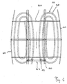
- a web guide 126 arranged which a A plurality of turns 128 includes and at a lower end the inner holding member 112 is too open.
- the dispensing device 16 On this track 126 is the dispensing device 16, which in particular is designed as an energy chain.
- the single ones Windings 128 of the web guide 126 are arranged in this way and designed that the dispensing device 16 at Transition from the use position 26 to the transport position 24 by means of the displacement of the rack device 94 in the Web guide 126 is slidable, d. H. there doesn't have to be an additional one Drive for guiding the dispensing device 16 in the Recording space 38 are provided.
- turns 128 are not too tight. A compromise can then be found between wide turns with a correspondingly high space requirement and narrow turns with reduced space requirements poorer leadership characteristics, especially in curves.
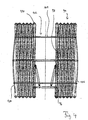
- the receiving space 38 is shown from above.
- This is formed in a closed magazine container 130, which has a substantially rectangular cross section.
- the mast 110 is arranged between this magazine container 130 and the tank 14 .
- Connection lines 132 through the mast 110, for example the delivery device 16 on the web guide 126, so that Liquid from the tank into the dispenser 16 (in 7 not shown) can be fed.
- a control valve is provided (in the drawing not shown) through which the fluid supply from the tank 14 controllable to the dispensing device 16 and in particular can also be switched off.
- the parallelogram structure 32 of the rack device 94 comprises individual parallelogram structures lying transversely next to one another.
- the inner holding member includes 112, as shown in Figure 8, three substantially the same design individual holding elements 136a, 136b and 136c, wherein the support 120 is hinged to the holding element 136a.
- the Holding element 136b in turn is slidable on the mast 110 out and the outer holding members 136a and 136c hinged to the holding member 136b that they with respect this holding element 136b are non-rotatable, i. H. deal with the Swivel holding element 136b and accordingly also over the Holding element 136b are slidably guided on the mast 110.
- the inner holding element 112 by three holding elements 136a, b, c is formed, is the stability of the inner retaining element 112 increased, the constructive Effort is essentially not increased since the individual Holding elements 136a, b and c are of substantially the same design are. Depending on the load, more or fewer individual holding elements can be provided (load-optimized stratification).
- a doubling 140 is provided to increase stability.
- the rack device is basically designed such as described above in connection with Figure 3.
- the same reference numerals are therefore used for the same components used.
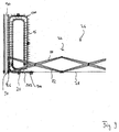
- a Web guide 140 in the receiving space 38 for the dispensing device 16 provided.
- the spreading device 16 comprises an energy chain 142, which in turn is composed of individual chain links 144, which are arranged and designed in this way, that the energy chain 142 is so flexible that it is on the Web guide 140 is feasible and in an operational position the use position 26 of the frame device 22 can be brought and from their operational position again on the web guide 140 can be pushed back into the receiving space 38, but transversely to the application line 28 in the direction of the pivot axis of the parallelogram structure 32 has a very limited flexibility.
- the energy chain 142 is at a front end with the outer Holding element 68 connected (not shown in Figure 9).
- Nozzles 20 are located in the energy chain at a certain distance arranged, this distance the distance between the nozzles in the Use position 26 corresponds to the rack device 22.
- the individual nozzles are connected via a hose 146 (cf. figures 12, 13) connected to each other and so with liquid from the Tank 18 can be supplied.
- hose 146 cf. figures 12, 13
- a spindle guide is provided (FIGS. 10, 11, 14, 15).
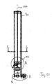
- the mast is in a sectional view shown, where the rack 22 in the operating position 26 is.
- the first cross arm 82 is on the mast displaceable via a spindle 148.
- This spindle is with provided with an external thread 150, which in a corresponding Internal thread 152 of a thread guide 154 on the first Cross arm 82 engages.
- the thread guide 154 By turning the spindle 148 then the thread guide 154 relative to the spindle 148 shift and thereby a movability of the first Form cross arms 82 on mast 30 (FIG. 15).
- a crank drive 156 can be provided for the rotation of the spindle 148, as in FIGS. 10 and 11, a crank drive 156 can be provided.
- This comprises a rotatably mounted handle 158, one of which Axis of rotation 160 transverse to a longitudinal direction 162 of mast 30 is ( Figure 10).
- An assigned rotary shaft 164 is over Rotary bearing 166 rotatably supported on the mast 30.
- a bevel gear 168 which in a bevel gear 170 engages, which is collinear about an axis of rotation to the longitudinal direction 162 of the mast 30 is rotatable.
- Through the bevel gears 168 and 170 becomes rotation of the rotary shaft 164 about the axis of rotation 116 converted into a rotation about the longitudinal direction 162.
- the bevel gear 170 is connected to the spindle 148, so to be able to turn the spindle via the handle 158 and thereby the first cross arm 82 in the longitudinal direction 162 on the To be able to move mast 30.
- the spindle 148 is in a pivot bearing 172 on the mast 30 stored.
- a Motor drive 174 for driving the rotational movement of the spindle 148 be provided.
- the motor drive 174 brings one Pulley 176 in rotation over a transmission belt 178 a pulley which is fixedly attached to the spindle 148 180 drives and thus the rotation of the spindle 148 caused to move along the direction 162 on the mast 30.
- the motor drive 174 is located in particular on or in the vicinity a lower end of the mast 30.
- the motor drive 174 of the passenger compartment of the tractor 10 is controllable, so that the driver extends and retracts the rack 22 can without leaving the passenger compartment.
- a holding member 36 provided with a guide profile 182, which in Cross-section is rectangular.
- the energy chain 142 is guided.
- On Guide profile 182 enables guidance parallel to Spreading line 28 and keeps the energy chain both across Spreading line as well as with respect to the vertical direction.
- On Guide profile 182 preferably sits on or in the vicinity of a joint 58 of a holding element 36.
- the energy chain comprises one U-shaped, down in the spray or spray direction
- Nozzle 20 opened U-shaped protective strip 184, which serves to avoid damage to a nozzle 20.
- a nozzle 20 by means of Liquid can be sprayed down onto a field, for example or is sprayable.
- the nozzle 20 itself is for example by means of a positive connection 186 in the corresponding Chain link of the energy chain 142 held. She is with that Hose 146 via a corresponding feed channel 188 connected.
- An adjusting pin 190 is a nozzle 20 in a chain link assigned by which the nozzle 20 can be switched off.
- the setting pin 190 is arranged and designed such that when a nozzle is inserted into the magazine container 130, is switched off automatically.
- the magazine container 130 has a guide contour (Not shown in the drawing), which has the setting pin 190 presses into a blocking position, which in turn nozzle 20 locks as shown in Figure 13.
- the nozzle 20 is via the energy chain 142 from the magazine container 130, then the setting pin 190, which is spring loaded in particular or in an alternative Embodiment is performed self-locking, d. H. yourself only moved with external force, from its Forced guidance move out and thus the assigned one Release the nozzle, as shown in Figure 12, so that it comes with Liquid is supplied and spray or can inject.
- the device for dispensing liquid according to the invention on an area works as follows:
- the tractor 10 is driven into a field with a full tank, the frame means 22 and 94 when driving is outside the field in the transport position 24 and the Spreading device 16 in the receiving space 38 on the drum 40 is wound or lies in the web guide 126.
- the rack device is extended by the support 120 is extended or the spindle 148 in Rotation is offset.
- a hydraulic drive or a Motor drive 174 is provided, taking the driver from the passenger compartment can control from the corresponding drive.
- the Holding elements 36 thereby move from the mast 30 or the mast 110 away, the diagonal 34 of the corresponding Parallelogram structure 32 extended.
- the nozzles 20 in the application line 28 on the frame device 22 or 94 held and in particular kept at an equal distance. This allows fluid to flow in in a short period of time applied a large area to, for example, a field become, d. H. sprayed or sprayed on.
- the nozzles 20 are automatically switched on. It can also be provided that each nozzle 20 is individual is controllable.
- the hydraulic drive or the motor drive 124 actuated so that the corresponding Rack device 22 and 94 from their operational position 26 returns to the transport position 24. Thereby the delivery device 16 into the receiving space 38 moved back.
- the hydraulic drive or the motor drive 124 actuated so that the corresponding Rack device 22 and 94 from their operational position 26 returns to the transport position 24.
- the delivery device 16 into the receiving space 38 moved back.
- the energy chain 142 automatically pushed back into the web guide 126 when the Frame device from the use position 26 in the transport position 24 is moved.
- a mast 192 provided which is pivotally arranged with a direction of rotation across the spreading line 28.
- the mast 192 comprises holding elements in a telescopic arrangement 194 ( Figure 17), which can be extended. With the Displacement of the holding elements 194 becomes a corresponding one Spreading device 196 shifted.
- the holding elements are in a transport position 198 (FIG. 16) 194 retracted into mast 192 and mast 192 is unmoved.
- an operating position 200 Figure 16
- the mast is pivoted and essentially parallel to the spreading line 28 aligned (thereby the application line 28 defined) and the holding elements 194 are extended.
- the delivery device 196 is in turn connected to the Nozzles 20 brought into an operating position, d. H. the nozzles 20 are aligned with the application line 28.
Landscapes
- Life Sciences & Earth Sciences (AREA)
- Environmental Sciences (AREA)
- Pest Control & Pesticides (AREA)
- Wood Science & Technology (AREA)
- Zoology (AREA)
- Engineering & Computer Science (AREA)
- Insects & Arthropods (AREA)
- Catching Or Destruction (AREA)
- Automatic Analysis And Handling Materials Therefor (AREA)
- Sampling And Sample Adjustment (AREA)
- Feeding, Discharge, Calcimining, Fusing, And Gas-Generation Devices (AREA)
- External Artificial Organs (AREA)
- Massaging Devices (AREA)
- Infusion, Injection, And Reservoir Apparatuses (AREA)
- Replacement Of Web Rolls (AREA)
Abstract
Description
- Figur 1
- eine schematische Hinteransicht eines Schleppers, an welchem ein erstes Ausführungsbeispiel einer erfindungsgemäßen Vorrichtung montiert ist, wobei diese Vorrichtung in der Transportstellung ist;
- Figur 2
- die Vorrichtung gemäß Figur 2 in der Einsatzstellung;
- Figur 3
- eine Teildarstellung des ersten Ausführungsbeispiels gemäß Figur 1 mit einer Gestelleinrichtung in Transportstellung und Einsatzstellung;
- Figur 4
- ein zweites Ausführungsbeispiel einer Gestelleinrichtung in der Transportstellung;
- Figur 5
- ein Halteelement der Ausführungsform gemäß Figur 4 in der Einsatzstellung;
- Figur 6
- ein Ausführungsbeispiel einer Führungsbahn in einem Aufnahmeraum;
- Figur 7
- eine obere Schnittansicht einer Ausführungsform einer erfindungsgemäßen Vorrichtung, wobei die Gestelleinrichtung nicht gezeigt ist;
- Figur 8
- ein Ausführungsbeispiel einer Gestelleinrichtung, welche an der Ausführungsform gemäß Figur 7 vorgesehen ist;
- Figur 9
- eine Teilansicht eines weiteren Ausführungsbeispiels einer erfindungsgemäßen Gestelleinrichtung;
- Figur 10
- eine Schnittansicht eines Mastes bei einer Ausführungsform einer erfindungsgemäßen Vorrichtung;
- Figur 11
- eine Detailansicht des Bereichs A gemäß Figur 10;
- Figur 12
- eine Detailansicht des Bereichs B gemäß Figur 10, wobei die Gestelleinrichtung in einer Einsatzstellung ist;
- Figur 13
- die gleiche Ansicht wie Figur 12, wobei die Gestelleinrichtung in der Transportstellung ist;
- Figur 14
- eine Schnittansicht längs der Linie C-C gemäß Figur 10;
- Figur 15
- eine Detailansicht einer Spindelführung im Zusammenhang mit der Ausführungsform gemäß Figur 10;
- Figur 16
- eine schematische Hinteransicht eines Schleppers, an welchem ein weiteres Ausführungsbeispiel einer erfindungsgemäßen Vorrichtung montiert ist, wobei die entsprechende Gestelleinrichtung in der Transportstellung ist und
- Figur 17
- die gleiche Ansicht wie Figur 17, wobei die Gestelleinrichtung in der Einsatzstellung ist.
Claims (47)
- Fahrbare Vorrichtung zum Ausbringen einer Flüssigkeit auf eine Fläche mit einer Ausbringeinrichtung (16; 196), welche Düsen (20) und eine oder mehrere Zuführungsleitungen (146) zu den Düsen umfaßt, und mit einer Gestelleinrichtung (22; 94; 192) zum Halten der Ausbringeinrichtung (16; 196), wobei die Gestelleinrichtung eine Einsatzstellung (26; 200) aufweist, in der Düsen (20) bezüglich einer Ausbringlinie (28) ausgerichtet sind, und eine Transportstellung (24; 198) aufweist, in welcher eine Querabmessung der Gestelleinrichtung im Vergleich zur Einsatzstellung (26; 200) bezogen auf eine Fahrtrichtung verringert ist,
dadurch gekennzeichnet, daß die Gestelleinrichtung ein oder mehrere verschiebliche Halteelemente (36; 194) umfaßt, durch deren Verschiebung die Gestelleinrichtung von der Transportstellung (24; 198) in die Einsatzstellung (26; 200) bringbar ist. - Vorrichtung nach Anspruch 1, dadurch gekennzeichnet, daß das oder die Halteelemente (36; 194) so angeordnet und ausgebildet sind, daß sie im wesentlichen parallel zu der Ausbringlinie (28) oder längs der Ausbringlinie (28) verschieblich sind.
- Vorrichtung nach Anspruch 1 oder 2, dadurch gekennzeichnet, daß ein Aufnahmeraum (38) zur zumindest teilweisen Aufnahme der Ausbringeinrichtung (16) in der Transportstellung (24) der Gestelleinrichtung (22) vorgesehen ist.
- Vorrichtung nach Anspruch 3, dadurch gekennzeichnet, daß der Aufnahmeraum (38) geschlossen ist.
- Vorrichtung nach einem der vorangehenden Ansprüche, dadurch gekennzeichnet, daß eine Düse (20) an eine Zuführungsleitung (146) gekoppelt ist.
- Vorrichtung nach einem der vorangehenden Ansprüche, dadurch gekennzeichnet, daß zur Führung von Düsen (20) und einer oder mehreren Zuführungsleitungen (146) eine Energiekette (142) vorgesehen ist.
- Vorrichtung nach einem der Ansprüche 3 bis 6, dadurch gekennzeichnet, daß durch Bewegen der Gestelleinrichtung (22; 94) von der Transportstellung (24) in die Einsatzstellung (26) die Ausbringeinrichtung (16) aus dem Aufnahmeraum (38) in eine Einsatzstellung bringbar ist.
- Vorrichtung nach Anspruch 7, dadurch gekennzeichnet, daß die Ausbringeinrichtung (16) an ein äußeres Halteelement (68) der Gestelleinrichtung (22) so gekoppelt ist, daß beim Bewegen dieses Halteelements (68) in die Einsatzstellung (26) die Ausbringeinrichtung (16) in ihre Einsatzstellung bringbar ist.
- Vorrichtung nach einem der Ansprüche 3 bis 8, dadurch gekennzeichnet, daß die Ausbringeinrichtung (16) durch Bewegen der Gestelleinrichtung (22; 94) aus der Einsatzstellung (26) in die Transportstellung (24) zumindest teilweise in den Aufnahmeraum (38) bringbar ist.
- Vorrichtung nach einem der Ansprüche 3 bis 9, dadurch gekennzeichnet, daß in dem Aufnahmeraum (38) eine Trommel (40) zum Aufwickeln der Ausbringeinrichtung (16) angeordnet ist.
- Vorrichtung nach Anspruch 10, dadurch gekennzeichnet, daß ein gesteuerter Antrieb für die Trommel (40) vorgesehen ist, mittels welchem sich beim Bewegen der Gestelleinrichtung (22) von der Einsatzstellung (26) in die Transportstellung (24) die Ausbringeinrichtung (16) synchron mit der Bewegung der Halteelemente (36) auf die Trommel (40) aufwickelbar ist.
- Vorrichtung nach einem der Ansprüche 3 bis 9, dadurch gekennzeichnet, daß in dem Aufnahmeraum (38) eine Bahnführung (126) für die Ausbringeinrichtung (16) angeordnet ist.
- Vorrichtung nach Anspruch 12, dadurch gekennzeichnet, daß die Bahnführung (126) in Windungen (128) ausgebildet ist.
- Vorrichtung nach Anspruch 12 oder 13, dadurch gekennzeichnet, daß die Bahnführung (126) so angeordnet und ausgebildet ist, daß beim Bewegen der Gestelleinrichtung (94) von der Einsatzstellung (26) in die Transportstellung (24) die Ausbringeinrichtung (16) in der Bahnführung (126) verschiebbar ist.
- Vorrichtung nach einem der Ansprüche 3 bis 14, dadurch gekennzeichnet, daß jede Düse (20) individuell ansteuerbar ist.
- Vorrichtung nach einem der Ansprüche 3 bis 15, dadurch gekennzeichnet, daß eine Düse so ausgebildet ist, daß sie beim Einfahren in den Aufnahmeraum (38) sperrbar ist.
- Vorrichtung nach einem der Ansprüche 3 bis 16, dadurch gekennzeichnet, daß eine Düse (20) so ausgebildet ist, daß sie beim Ausfahren aus dem Aufnahmeraum (38) einschaltbar ist.
- Vorrichtung nach Anspruch 16 oder 17, dadurch gekennzeichnet, daß eine Düse mit einem Stellstift (119) versehen ist, welcher außerhalb des Aufnahmeraums (38) in einer Freigabestellung ist und beim Einfahren in den Aufnahmeraum (38) in eine Sperrstellung bringbar ist, bei der die zugeordnete Düse gesperrt ist.
- Vorrichtung nach Anspruch 18, dadurch gekennzeichnet, daß der Aufnahmeraum (38) mit einer Einführungsbahn versehen ist, durch die beim Einfahren einer Düse (20) in den Aufnahmeraum (38) ein Stellstift (190) der Düse (20) von der Freigabestellung in die Sperrstellung bringbar ist.
- Vorrichtung nach einem der Ansprüche 3 bis 19, dadurch gekennzeichnet, daß die Gestelleinrichtung (22; 94) zwischen einem Tank (14) und dem Aufnahmeraum (38) angeordnet ist.
- Vorrichtung nach einem der vorangehenden Ansprüche,
dadurch gekennzeichnet, daß zur Verschiebungsführung der Halteelemente (194) eine Teleskopführung vorgesehen ist. - Vorrichtung nach Anspruch 21, dadurch gekennzeichnet, daß ein Führungsmast (192) für die Teleskopführung vorgesehen ist, welcher um eine Achse quer zur Ausbringlinie (28) schwenkbar ist.
- Vorrichtung nach einem der Ansprüche 1 bis 20, dadurch gekennzeichnet, daß die Gestelleinrichtung (22; 94) eine diagonalenvariable Parallelogrammstruktur (32) umfaßt.
- Vorrichtung nach Anspruch 23, dadurch gekennzeichnet, daß eine längenvariable Diagonale (34) im wesentlichen parallel zur Ausbringlinie (28) orientiert ist.
- Vorrichtung nach Anspruch 23 oder 24, dadurch gekennzeichnet, daß die Vorrichtung einen Mast (30; 110) aufweist, an dem die Parallelogrammstruktur (32) in einem Punkt außerhalb der variablen Diagonale (34) schwenkbar angelenkt ist und in einem weiteren Punkt außerhalb der Diagonale zur Variation der Diagonalen schwenkverschieblich angelenkt ist.
- Vorrichtung nach einem der Ansprüche 23 bis 25, dadurch gekennzeichnet, daß benachbarte Halteelemente (36, 50) so aneinander angelenkt sind, daß mittels ihnen ein Parallelogramm (52) mit variabler Diagonale (34) gebildet ist.
- Vorrichtung nach einem der Ansprüche 23 bis 26, dadurch gekennzeichnet, daß ein Halteelement (26) einen ersten Kreuzarm (44) und einen zweiten Kreuzarm (46) umfaßt, welche schwenkbar aneinander angelenkt sind.
- Vorrichtung nach Anspruch 27, dadurch gekennzeichnet, daß erster und zweiter Kreuzarm (44, 46) im wesentlichen mittig aneinander angelenkt sind.
- Vorrichtung nach Anspruch 27, dadurch gekennzeichnet, daß erster Kreuzarm (44) und zweiter Kreuzarm (46) versetzt bezüglich ihrer Mitte aneinander angelenkt sind.
- Vorrichtung nach einem der Ansprüche 27 bis 29, dadurch gekennzeichnet, daß Kreuzarme (44, 60; 46, 56) benachbarter Halteelemente (36, 50) so schwenkbar aneinander angelenkt sind, daß zwischen den Kreuzarmen ein Parallelogramm (52) mit variabler Diagonale (34) gebildet ist.
- Vorrichtung nach Anspruch 30, dadurch gekennzeichnet, daß eine variable Diagonale (34) zwischen dem Anlenkpunkt (48) des ersten und zweiten Kreuzarms (44, 46) eines Halteelements (36) und dem entsprechenden Anlenkpunkt (54) eines benachbarten Halteelements (50) liegt.
- Vorrichtung nach einem der Ansprüche 27 bis 31, dadurch gekennzeichnet, daß ein erster Kreuzarm (80) eines inneren Halteelements (66) schwenkverschieblich an einem Mast (30) und ein zweiter Kreuzarm (88) des inneren Halteelements (66) schwenkbar an dem Mast (30) angeordnet ist.
- Vorrichtung nach einem der Ansprüche 23 bis 32, dadurch gekennzeichnet, daß eine Schwenkachse der Parallelogrammstruktur (52) zur Diagonalvariation in der Parallelogrammstruktur (32) quer zur Ausbringlinie (28) liegt.
- Vorrichtung nach einem der Ansprüche 27 bis 33, dadurch gekennzeichnet, daß ein Kreuzarm durch ein Lochblech gebildet ist.
- Vorrichtung nach einem der Ansprüche 23 bis 34, dadurch gekennzeichnet, daß eine Mehrzahl von Parallelogrammstrukturen gleicher Diagonalvariabilität quer zur Ausbringlinie (28) nebeneinander angeordnet ist.
- Vorrichtung nach einem der Ansprüche 25 bis 35, dadurch gekennzeichnet, daß ein inneres Halteelement über eine Spindelführung verschieblich an dem Mast (30) geführt ist.
- Vorrichtung nach einem der Ansprüche 25 bis 35, dadurch gekennzeichnet, daß ein inneres Halteelement über eine Drehschiebeführung (114) verschieblich an dem Mast (30) angelenkt ist.
- Vorrichtung nach Anspruch 37, dadurch gekennzeichnet, daß das innere Halteelement über eine Stütze (120) an dem Mast (110) beweglich ist.
- Vorrichtung nach einem der Ansprüche 25 bis 38, dadurch gekennzeichnet, daß ein Antrieb zur Verschiebung des Anlenkpunkts (118) einer Parallelogrammstruktur (32) an dem Mast (110; 30) vorgesehen ist.
- Vorrichtung nach Anspruch 39, dadurch gekennzeichnet, daß ein Hydraulikantrieb vorgesehen ist.
- Vorrichtung nach Anspruch 40, dadurch gekennzeichnet, daß über den Hydraulikantrieb eine Stütze (120) beweglich ist, an welche ein inneres Halteelement (112) angelenkt ist.
- Vorrichtung nach einem der Ansprüche 39 bis 41, dadurch gekennzeichnet, daß ein Spindelantrieb vorgesehen ist, mittels dem eine Spindel (148) drehbar ist, so daß dadurch ein Anlenkpunkt eines inneren Halteelements an dem Mast (30) verschieblich ist.
- Vorrichtung nach einem der Ansprüche 39 bis 42, dadurch gekennzeichnet, daß ein handbetätigbarer Antrieb (156) vorgesehen ist.
- Vorrichtung nach einem der vorangehenden Ansprüche, dadurch gekennzeichnet, daß an einem Halteelement ein Führungsprofil (182) für die Ausbringeinrichtung (16) sitzt.
- Vorrichtung nach Anspruch 44, dadurch gekennzeichnet, daß in der Transportstellung (24) der Gestelleinrichtung (22; 94) die Ausbringeinrichtung (16) in Führungsprofilen (182) der Halteelemente (36) liegt.
- Vorrichtung nach einem der vorangehenden Ansprüche, dadurch gekennzeichnet, daß die Bewegung der Gestelleinrichtung (22; 94; 192) über Antriebseinrichtungen steuerbar ist.
- Vorrichtung nach Anspruch 46, dadurch gekennzeichnet, daß die Bewegung der Gestelleinrichtung (22; 94; 192) von einer Fahrgastzelle aus steuerbar ist.
Applications Claiming Priority (2)
| Application Number | Priority Date | Filing Date | Title |
|---|---|---|---|
| DE10013800 | 2000-03-20 | ||
| DE10013800A DE10013800A1 (de) | 2000-03-20 | 2000-03-20 | Fahrbare Vorrichtung zum Ausbringen einer Flüssigkeit |
Publications (5)
| Publication Number | Publication Date |
|---|---|
| EP1138200A2 true EP1138200A2 (de) | 2001-10-04 |
| EP1138200A3 EP1138200A3 (de) | 2002-06-12 |
| EP1138200A9 EP1138200A9 (de) | 2002-10-09 |
| EP1138200B1 EP1138200B1 (de) | 2005-10-26 |
| EP1138200B2 EP1138200B2 (de) | 2010-09-01 |
Family
ID=7635649
Family Applications (1)
| Application Number | Title | Priority Date | Filing Date |
|---|---|---|---|
| EP01106776A Expired - Lifetime EP1138200B2 (de) | 2000-03-20 | 2001-03-17 | Fahrbare Vorrichtung zum Ausbringen einer Flüssigkeit |
Country Status (4)
| Country | Link |
|---|---|
| EP (1) | EP1138200B2 (de) |
| AT (1) | ATE307480T1 (de) |
| DE (2) | DE10013800A1 (de) |
| DK (1) | DK1138200T3 (de) |
Cited By (1)
| Publication number | Priority date | Publication date | Assignee | Title |
|---|---|---|---|---|
| EP3488687A1 (de) * | 2017-11-22 | 2019-05-29 | Koiviston Kukka ja Hautaus Oy | Bewässerungsvorrichtung und eine anordnung |
Families Citing this family (2)
| Publication number | Priority date | Publication date | Assignee | Title |
|---|---|---|---|---|
| DE102007001915A1 (de) | 2006-01-26 | 2007-08-09 | Lemken Gmbh & Co. Kg | Spritzgestänge für Feldspritzen |
| DE102021114405A1 (de) * | 2021-06-03 | 2022-12-08 | Amazonen-Werke H. Dreyer SE & Co. KG | Gestänge eines landwirtschaftlichen Geräts und Feldspritze |
Citations (1)
| Publication number | Priority date | Publication date | Assignee | Title |
|---|---|---|---|---|
| DE3401734C2 (de) | 1984-01-19 | 1987-03-26 | Gebrüder Holder GmbH & Co, 7430 Metzingen | Spritz- bzw. Sprühvorrichtung |
Family Cites Families (10)
| Publication number | Priority date | Publication date | Assignee | Title |
|---|---|---|---|---|
| DE1974964U (de) * | 1967-07-06 | 1967-12-14 | Amazonen Werke Dreyer H | Mit spritzbalken versehene maschine zum verteilen von fluessigkeiten. |
| FR2254176A5 (en) * | 1973-11-12 | 1975-07-04 | Bersoult Roland | Extensible spray bar for agricultural use - has nozzles on lazy-tongs system extending in two planes |
| GB2039202A (en) † | 1979-01-12 | 1980-08-06 | Curtis Long Dev Ltd | A control system for an agricultural spraying machine or the like |
| WO1983002713A1 (en) * | 1982-02-10 | 1983-08-18 | Sidler Helen Legal Representat | Irrigation ramp |
| FR2541912B1 (fr) * | 1983-03-03 | 1988-08-19 | Seguip | Perfectionnements aux rampes de pulverisation agricole |
| EP0118366B1 (de) † | 1983-03-03 | 1987-06-10 | Seguip | Spritzgestänge für die Landwirtschaft |
| FR2639507B1 (fr) † | 1988-11-28 | 1991-05-10 | Barlet Christian | Procede et dispositif pour l'epandage programme d'un produit actif a la surface du sol |
| DK213389A (da) * | 1989-05-02 | 1990-11-03 | Gunnar Arenhoff Eriksen | Mobilt vandingsapparat med ud- og indfoldelig spredebom |
| DE3938868A1 (de) † | 1989-11-24 | 1991-05-29 | Amazonen Werke Dreyer H | Landwirtschaftliche verteilmaschine |
| FR2776890B1 (fr) * | 1998-04-06 | 2000-05-19 | Francois Lapeyre | Dispositif autonome de distribution de produits de traitement en enceinte fermee et systeme de positionnement dudit dispositif |
-
2000
- 2000-03-20 DE DE10013800A patent/DE10013800A1/de not_active Withdrawn
-
2001
- 2001-03-17 EP EP01106776A patent/EP1138200B2/de not_active Expired - Lifetime
- 2001-03-17 AT AT01106776T patent/ATE307480T1/de not_active IP Right Cessation
- 2001-03-17 DE DE50107789T patent/DE50107789D1/de not_active Expired - Lifetime
- 2001-03-17 DK DK01106776T patent/DK1138200T3/da active
Patent Citations (1)
| Publication number | Priority date | Publication date | Assignee | Title |
|---|---|---|---|---|
| DE3401734C2 (de) | 1984-01-19 | 1987-03-26 | Gebrüder Holder GmbH & Co, 7430 Metzingen | Spritz- bzw. Sprühvorrichtung |
Cited By (1)
| Publication number | Priority date | Publication date | Assignee | Title |
|---|---|---|---|---|
| EP3488687A1 (de) * | 2017-11-22 | 2019-05-29 | Koiviston Kukka ja Hautaus Oy | Bewässerungsvorrichtung und eine anordnung |
Also Published As
| Publication number | Publication date |
|---|---|
| DK1138200T3 (da) | 2006-03-13 |
| EP1138200A3 (de) | 2002-06-12 |
| DE50107789D1 (de) | 2005-12-01 |
| ATE307480T1 (de) | 2005-11-15 |
| EP1138200B1 (de) | 2005-10-26 |
| EP1138200A9 (de) | 2002-10-09 |
| DE10013800A1 (de) | 2001-10-04 |
| EP1138200B2 (de) | 2010-09-01 |
Similar Documents
| Publication | Publication Date | Title |
|---|---|---|
| DE2801116B2 (de) | Klappbarer Geräteträger mit zwei Werkzeugtragrahmen | |
| AT409485B (de) | Teleskopausleger für ein fahrzeug oder ein hebezeug | |
| DE1474238B2 (de) | Vorrichtung zum bodenfreien abstuetzen einer schweren rolle | |
| DD153404A5 (de) | Gleisstopfmaschine | |
| DE4441142C2 (de) | Zweirichtungsschwenkrahmen einer Papierrollenwechseleinrichtung | |
| DE8814129U1 (de) | Gerät zum Bestäuben von Druckerzeugnissen | |
| EP1138200B1 (de) | Fahrbare Vorrichtung zum Ausbringen einer Flüssigkeit | |
| EP1452472B1 (de) | Vorrichtung zum Umlenken einer Bahn | |
| DE3517724A1 (de) | Verlegesystem fuer brueckenelemente | |
| DE2540644C3 (de) | Längenveränderbare Stange, insbesondere Erdungsstange oder Betätigungsstange für elektrotechnische Einrichtungen | |
| DE4240125C2 (de) | Hydraulische Absetzeinrichtung für Wechselaufbauten | |
| DE3541588C2 (de) | ||
| EP3523161B1 (de) | Fahrzeug, insbesondere einsatzfahrzeug, mit einer ladeanordnung | |
| DE10159717A1 (de) | Ofenklappen für Wickelöfen | |
| DE3130328C2 (de) | Kettbaumwagen | |
| DE4125129C1 (en) | Mechanism for lateral-shift or road side barrier - has support arm length movable to max. width of construction vehicle and swivelable about horizontal axis | |
| DE19937486B4 (de) | Transportfahrzeug zur Entnahme eines Warenbaums aus einer Webmaschine, Schneidvorrichtung für das Transportfahrzeug zum Abtrennen einer Warenbahn und Verfahren zur Entnahme des Warenbaums aus der Webmaschine | |
| DE2938614A1 (de) | Hubvorrichtung | |
| DE60023506T2 (de) | Telekopiersystem eines Kranauslegers | |
| DE19856222A1 (de) | Teleskoptribüne | |
| EP0588883A1 (de) | Scheibenwischeranlage. | |
| DE3419980C1 (de) | Dachgepäckträger für Fahrzeuge | |
| DE102022102318A1 (de) | Mobilkran mit abgespanntem Teleskopausleger | |
| DE4406061A1 (de) | Vorrichtung für Einsatzfahrzeuge, insbesondere Feuerwehrfahrzeuge, zum Ausüben einer Rückholkraft auf einen schubladenartig bewegbaren Schieber | |
| DE2839075A1 (de) | Steuervorrichtung zum schliessen eines faltbaren wohnwagens |
Legal Events
| Date | Code | Title | Description |
|---|---|---|---|
| PUAI | Public reference made under article 153(3) epc to a published international application that has entered the european phase |
Free format text: ORIGINAL CODE: 0009012 |
|
| AK | Designated contracting states |
Kind code of ref document: A2 Designated state(s): AT BE CH CY DE DK ES FI FR GB GR IE IT LI LU MC NL PT SE TR |
|
| AX | Request for extension of the european patent |
Free format text: AL;LT;LV;MK;RO;SI |
|
| PUAL | Search report despatched |
Free format text: ORIGINAL CODE: 0009013 |
|
| AK | Designated contracting states |
Kind code of ref document: A3 Designated state(s): AT BE CH CY DE DK ES FI FR GB GR IE IT LI LU MC NL PT SE TR |
|
| AX | Request for extension of the european patent |
Free format text: AL;LT;LV;MK;RO;SI |
|
| RAP1 | Party data changed (applicant data changed or rights of an application transferred) |
Owner name: GEBRUEDER HOLDER GMBH |
|
| 17P | Request for examination filed |
Effective date: 20021126 |
|
| AKX | Designation fees paid |
Designated state(s): AT BE CH CY DE DK ES FI FR GB GR IE IT LI LU MC NL PT SE TR |
|
| 17Q | First examination report despatched |
Effective date: 20040323 |
|
| GRAP | Despatch of communication of intention to grant a patent |
Free format text: ORIGINAL CODE: EPIDOSNIGR1 |
|
| GRAS | Grant fee paid |
Free format text: ORIGINAL CODE: EPIDOSNIGR3 |
|
| GRAA | (expected) grant |
Free format text: ORIGINAL CODE: 0009210 |
|
| AK | Designated contracting states |
Kind code of ref document: B1 Designated state(s): AT BE CH CY DE DK ES FI FR GB GR IE IT LI LU MC NL PT SE TR |
|
| PG25 | Lapsed in a contracting state [announced via postgrant information from national office to epo] |
Ref country code: IE Free format text: LAPSE BECAUSE OF FAILURE TO SUBMIT A TRANSLATION OF THE DESCRIPTION OR TO PAY THE FEE WITHIN THE PRESCRIBED TIME-LIMIT Effective date: 20051026 Ref country code: IT Free format text: LAPSE BECAUSE OF FAILURE TO SUBMIT A TRANSLATION OF THE DESCRIPTION OR TO PAY THE FEE WITHIN THE PRESCRIBED TIME-LIMIT;WARNING: LAPSES OF ITALIAN PATENTS WITH EFFECTIVE DATE BEFORE 2007 MAY HAVE OCCURRED AT ANY TIME BEFORE 2007. THE CORRECT EFFECTIVE DATE MAY BE DIFFERENT FROM THE ONE RECORDED. Effective date: 20051026 Ref country code: FI Free format text: LAPSE BECAUSE OF FAILURE TO SUBMIT A TRANSLATION OF THE DESCRIPTION OR TO PAY THE FEE WITHIN THE PRESCRIBED TIME-LIMIT Effective date: 20051026 |
|
| REG | Reference to a national code |
Ref country code: GB Ref legal event code: FG4D Free format text: NOT ENGLISH |
|
| REG | Reference to a national code |
Ref country code: CH Ref legal event code: EP |
|
| REG | Reference to a national code |
Ref country code: IE Ref legal event code: FG4D Free format text: LANGUAGE OF EP DOCUMENT: GERMAN |
|
| REF | Corresponds to: |
Ref document number: 50107789 Country of ref document: DE Date of ref document: 20051201 Kind code of ref document: P |
|
| PG25 | Lapsed in a contracting state [announced via postgrant information from national office to epo] |
Ref country code: SE Free format text: LAPSE BECAUSE OF FAILURE TO SUBMIT A TRANSLATION OF THE DESCRIPTION OR TO PAY THE FEE WITHIN THE PRESCRIBED TIME-LIMIT Effective date: 20060126 Ref country code: GR Free format text: LAPSE BECAUSE OF FAILURE TO SUBMIT A TRANSLATION OF THE DESCRIPTION OR TO PAY THE FEE WITHIN THE PRESCRIBED TIME-LIMIT Effective date: 20060126 |
|
| PG25 | Lapsed in a contracting state [announced via postgrant information from national office to epo] |
Ref country code: ES Free format text: LAPSE BECAUSE OF FAILURE TO SUBMIT A TRANSLATION OF THE DESCRIPTION OR TO PAY THE FEE WITHIN THE PRESCRIBED TIME-LIMIT Effective date: 20060206 |
|
| REG | Reference to a national code |
Ref country code: CH Ref legal event code: NV Representative=s name: ISLER & PEDRAZZINI AG |
|
| GBT | Gb: translation of ep patent filed (gb section 77(6)(a)/1977) |
Effective date: 20060209 |
|
| REG | Reference to a national code |
Ref country code: DK Ref legal event code: T3 |
|
| PG25 | Lapsed in a contracting state [announced via postgrant information from national office to epo] |
Ref country code: PT Free format text: LAPSE BECAUSE OF FAILURE TO SUBMIT A TRANSLATION OF THE DESCRIPTION OR TO PAY THE FEE WITHIN THE PRESCRIBED TIME-LIMIT Effective date: 20060327 |
|
| PG25 | Lapsed in a contracting state [announced via postgrant information from national office to epo] |
Ref country code: MC Free format text: LAPSE BECAUSE OF NON-PAYMENT OF DUE FEES Effective date: 20060331 Ref country code: LU Free format text: LAPSE BECAUSE OF NON-PAYMENT OF DUE FEES Effective date: 20060331 |
|
| REG | Reference to a national code |
Ref country code: IE Ref legal event code: FD4D |
|
| ET | Fr: translation filed | ||
| PLBI | Opposition filed |
Free format text: ORIGINAL CODE: 0009260 |
|
| PLAX | Notice of opposition and request to file observation + time limit sent |
Free format text: ORIGINAL CODE: EPIDOSNOBS2 |
|
| 26 | Opposition filed |
Opponent name: AMAZONEN-WERKE H. DREYER GMBH & CO. KG Effective date: 20060720 |
|
| NLR1 | Nl: opposition has been filed with the epo |
Opponent name: AMAZONEN-WERKE H. DREYER GMBH & CO. KG |
|
| PLAF | Information modified related to communication of a notice of opposition and request to file observations + time limit |
Free format text: ORIGINAL CODE: EPIDOSCOBS2 |
|
| PGFP | Annual fee paid to national office [announced via postgrant information from national office to epo] |
Ref country code: BE Payment date: 20070117 Year of fee payment: 7 |
|
| PGFP | Annual fee paid to national office [announced via postgrant information from national office to epo] |
Ref country code: AT Payment date: 20070305 Year of fee payment: 7 |
|
| PLBB | Reply of patent proprietor to notice(s) of opposition received |
Free format text: ORIGINAL CODE: EPIDOSNOBS3 |
|
| PGFP | Annual fee paid to national office [announced via postgrant information from national office to epo] |
Ref country code: NL Payment date: 20070329 Year of fee payment: 7 |
|
| PGFP | Annual fee paid to national office [announced via postgrant information from national office to epo] |
Ref country code: CH Payment date: 20070404 Year of fee payment: 7 |
|
| REG | Reference to a national code |
Ref country code: CH Ref legal event code: PCAR Free format text: ISLER & PEDRAZZINI AG;POSTFACH 1772;8027 ZUERICH (CH) |
|
| PGFP | Annual fee paid to national office [announced via postgrant information from national office to epo] |
Ref country code: TR Payment date: 20070221 Year of fee payment: 7 |
|
| BERE | Be: lapsed |
Owner name: GEBRUDER *HOLDER G.M.B.H. Effective date: 20080331 |
|
| REG | Reference to a national code |
Ref country code: CH Ref legal event code: PL |
|
| PG25 | Lapsed in a contracting state [announced via postgrant information from national office to epo] |
Ref country code: CY Free format text: LAPSE BECAUSE OF FAILURE TO SUBMIT A TRANSLATION OF THE DESCRIPTION OR TO PAY THE FEE WITHIN THE PRESCRIBED TIME-LIMIT Effective date: 20051026 Ref country code: NL Free format text: LAPSE BECAUSE OF NON-PAYMENT OF DUE FEES Effective date: 20081001 Ref country code: AT Free format text: LAPSE BECAUSE OF NON-PAYMENT OF DUE FEES Effective date: 20080317 |
|
| NLV4 | Nl: lapsed or anulled due to non-payment of the annual fee |
Effective date: 20081001 |
|
| PG25 | Lapsed in a contracting state [announced via postgrant information from national office to epo] |
Ref country code: LI Free format text: LAPSE BECAUSE OF NON-PAYMENT OF DUE FEES Effective date: 20080331 Ref country code: CH Free format text: LAPSE BECAUSE OF NON-PAYMENT OF DUE FEES Effective date: 20080331 |
|
| PG25 | Lapsed in a contracting state [announced via postgrant information from national office to epo] |
Ref country code: BE Free format text: LAPSE BECAUSE OF NON-PAYMENT OF DUE FEES Effective date: 20080331 |
|
| RAP2 | Party data changed (patent owner data changed or rights of a patent transferred) |
Owner name: VOGEL & NOOT SPRAY SOLUTIONS GMBH |
|
| APBM | Appeal reference recorded |
Free format text: ORIGINAL CODE: EPIDOSNREFNO |
|
| APBP | Date of receipt of notice of appeal recorded |
Free format text: ORIGINAL CODE: EPIDOSNNOA2O |
|
| APAH | Appeal reference modified |
Free format text: ORIGINAL CODE: EPIDOSCREFNO |
|
| APBU | Appeal procedure closed |
Free format text: ORIGINAL CODE: EPIDOSNNOA9O |
|
| PGFP | Annual fee paid to national office [announced via postgrant information from national office to epo] |
Ref country code: DK Payment date: 20100330 Year of fee payment: 10 |
|
| PGFP | Annual fee paid to national office [announced via postgrant information from national office to epo] |
Ref country code: FR Payment date: 20100324 Year of fee payment: 10 |
|
| PGFP | Annual fee paid to national office [announced via postgrant information from national office to epo] |
Ref country code: GB Payment date: 20100317 Year of fee payment: 10 |
|
| PUAH | Patent maintained in amended form |
Free format text: ORIGINAL CODE: 0009272 |
|
| STAA | Information on the status of an ep patent application or granted ep patent |
Free format text: STATUS: PATENT MAINTAINED AS AMENDED |
|
| PGFP | Annual fee paid to national office [announced via postgrant information from national office to epo] |
Ref country code: DE Payment date: 20100423 Year of fee payment: 10 |
|
| 27A | Patent maintained in amended form |
Effective date: 20100901 |
|
| AK | Designated contracting states |
Kind code of ref document: B2 Designated state(s): AT BE CH CY DE DK ES FI FR GB GR IE IT LI LU MC NL PT SE TR |
|
| REG | Reference to a national code |
Ref country code: ES Ref legal event code: FD2A Effective date: 20060318 |
|
| PG25 | Lapsed in a contracting state [announced via postgrant information from national office to epo] |
Ref country code: DK Free format text: LAPSE BECAUSE OF FAILURE TO SUBMIT A TRANSLATION OF THE DESCRIPTION OR TO PAY THE FEE WITHIN THE PRESCRIBED TIME-LIMIT Effective date: 20101201 |
|
| PG25 | Lapsed in a contracting state [announced via postgrant information from national office to epo] |
Ref country code: TR Free format text: LAPSE BECAUSE OF NON-PAYMENT OF DUE FEES Effective date: 20100923 |
|
| GBPC | Gb: european patent ceased through non-payment of renewal fee |
Effective date: 20110317 |
|
| REG | Reference to a national code |
Ref country code: FR Ref legal event code: ST Effective date: 20111130 |
|
| PG25 | Lapsed in a contracting state [announced via postgrant information from national office to epo] |
Ref country code: FR Free format text: LAPSE BECAUSE OF NON-PAYMENT OF DUE FEES Effective date: 20110331 Ref country code: DE Free format text: LAPSE BECAUSE OF NON-PAYMENT OF DUE FEES Effective date: 20111001 |
|
| REG | Reference to a national code |
Ref country code: DE Ref legal event code: R119 Ref document number: 50107789 Country of ref document: DE Effective date: 20111001 |
|
| PG25 | Lapsed in a contracting state [announced via postgrant information from national office to epo] |
Ref country code: GB Free format text: LAPSE BECAUSE OF NON-PAYMENT OF DUE FEES Effective date: 20110317 |
|
| PG25 | Lapsed in a contracting state [announced via postgrant information from national office to epo] |
Ref country code: TR Free format text: LAPSE BECAUSE OF NON-PAYMENT OF DUE FEES Effective date: 20080317 |