EP1138219A2 - Spannhebel, insbesondere für Sportschuhe - Google Patents
Spannhebel, insbesondere für Sportschuhe Download PDFInfo
- Publication number
- EP1138219A2 EP1138219A2 EP01106893A EP01106893A EP1138219A2 EP 1138219 A2 EP1138219 A2 EP 1138219A2 EP 01106893 A EP01106893 A EP 01106893A EP 01106893 A EP01106893 A EP 01106893A EP 1138219 A2 EP1138219 A2 EP 1138219A2
- Authority
- EP
- European Patent Office
- Prior art keywords
- lever
- traction member
- bar
- flap
- free end
- Prior art date
- Legal status (The legal status is an assumption and is not a legal conclusion. Google has not performed a legal analysis and makes no representation as to the accuracy of the status listed.)
- Withdrawn
Links
Images


Classifications
-
- A—HUMAN NECESSITIES
- A43—FOOTWEAR
- A43B—CHARACTERISTIC FEATURES OF FOOTWEAR; PARTS OF FOOTWEAR
- A43B3/00—Footwear characterised by the shape or the use
- A43B3/0036—Footwear characterised by the shape or the use characterised by a special shape or design
- A43B3/0063—U-shaped
-
- A—HUMAN NECESSITIES
- A43—FOOTWEAR
- A43C—FASTENINGS OR ATTACHMENTS OF FOOTWEAR; LACES IN GENERAL
- A43C11/00—Other fastenings specially adapted for shoes
- A43C11/14—Clamp fastenings, e.g. strap fastenings; Clamp-buckle fastenings; Fastenings with toggle levers
- A43C11/1406—Fastenings with toggle levers; Equipment therefor
-
- A—HUMAN NECESSITIES
- A43—FOOTWEAR
- A43C—FASTENINGS OR ATTACHMENTS OF FOOTWEAR; LACES IN GENERAL
- A43C11/00—Other fastenings specially adapted for shoes
- A43C11/14—Clamp fastenings, e.g. strap fastenings; Clamp-buckle fastenings; Fastenings with toggle levers
- A43C11/1406—Fastenings with toggle levers; Equipment therefor
- A43C11/142—Fastenings with toggle levers with adjustment means provided for on the shoe, e.g. rack
- A43C11/1446—Fastenings with toggle levers with adjustment means provided for on the shoe, e.g. rack characterised by special protection means to prevent damage or accidental loosening of the fastening means
Definitions
- the present invention relates to a fastening lever, particularly for sports shoes such as ski boots, roller skates, ice skates, or ice-climbing boots.
- a problem encountered in sports shoes is to achieve optimum fastening of the flaps of a quarter or shell while maintaining good comfort.
- a conventional fastening lever is generally constituted by a lever arm articulated to a base which is rigidly coupled to a first member of the shoe and by a spring traction member which is associated with a second member of the shoe.
- the lever arm has, on its lower surface, a plurality of teeth for engaging the free end of the spring traction member, which is constituted by two parallel cylindrical springs which are mutually rigidly coupled at the free end of the traction member.
- such "elastic" lever has the advantage that it allows effective and uniform mutual closure of the two flaps over each other, while the springs tend to compensate for the differences in adjustment that frequently occur among the various levers of the sports shoe.
- a further drawback is that, during the fastening action, the two cylindrical springs are subjected to possibly considerable elongations according to the intended fastening that can be imparted to the lever.
- the springs are very large and are arranged outside the lever arm, in an exposed position, they are prone to breaking or at least to being damaged by impacts with objects, such as rocks, branches, other shoes, skis and anything else that might accidentally make contact with the sports shoe.
- a further drawback is that dirt, mud and grass blades, or any other solid object, such as small fragments of rocks, pebbles or ice fragments, can easily penetrate between the springs, causing possible defects in the operation of the lever and also possible damage thereto.
- a second conventional type of elastic lever is constituted by a lever arm, which is articulated to a base which protrudes from a first flap or member of a shoe, and by a traction member, which is associated with the second flap of the shoe and has elastically deformable parts.
- Teeth protrude downward from the lever arm and engage the free end of the traction member, which is constituted by two telescopic members which contain mutually parallel elastically deformable members.
- Each member has a hollow cylinder in which a piston is slidingly arranged, the piston being constituted by a head and a stem which protrudes outside the hollow cylinder in the opposite direction with respect to the second flap.
- a cylindrical spring which is coaxial to the stem, is arranged so that it is compressed by the head of the piston when the stem slides toward the outside of the cylinder, so as to contrast the elongation of the traction member.
- the stems of the pistons that lie outside the hollow cylinders are mutually connected so as to form the free end, which interacts with the teeth of the lever arm.
- This second type of conventional elastic lever too has the advantage of allowing effective and uniform closure of the two flaps.
- the lever in fact has a structure which is fully similar to the previously described conventional type of fastening lever and differs only in the type of elastically deformable member that is used.
- This second conventional type of lever has drawbacks which are similar to those of the preceding fastening lever.
- the lever arm is disadvantageous and the closure action becomes more and more difficult as the distance of the tooth used for connection to the free end of the traction member with respect to the pivoting point of the lever arm increases.
- the telescopic members are difficult to manufacture, because they are composed of several parts, most of which are small, requiring expensive precision processes.
- the aim of the present invention is to solve the above-noted drawbacks and the described technical problems, by providing a lever in which the user can achieve optimum comfort for the foot while maintaining a constant closure load.
- An object of the invention is to provide a lever which provides for a constant closure load even when the flaps, by settling and elongating, tend to reduce the initial closure load of the lever.
- Another important object is to provide a lever which reduces the number of adjustments of the closure of the various levers applied to the sports shoe.
- Another object is to provide a lever whose closure does not entail the accidental opening of an adjacent lever.
- Another object is to provide a lever in which it is possible to indicate the obtained closure load value.
- Another object is to provide a lever which is structurally simple and has low manufacturing costs.
- a lever particularly for sports shoes, comprising a base which is rigidly coupled to a first flap and is provided with two shoulders between which a U-shaped lever arm is articulated, a traction member being pivoted between the wings of said U-shaped arm, characterized in that said traction member is slidingly guided, at its free end, in two slots formed in a bar which has, at its free end, a pin which is selectively associated with one of a plurality of teeth of a rack which is associated with a second flap, said traction member sliding in contrast with a preloaded elastically deformable member which is adapted to maintain a constant closure load.
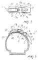
- the numeral 1 designates a lever particularly for sports shoes such as for example skates and ski boots.
- the lever 1 has a base 2, which is rigidly coupled to a first flap 3 of the sports shoe.
- the base 2 is flat and is laterally provided with two shoulders 4a and 4b that protrude at right angles to the first flap 3 and face each other so that a lever arm 5 can be articulated between them.
- the lever arm 5 is U-shaped so as to form two wings 6a and 6b that are pivoted, at their respective free ends, to the two shoulders 4a and 4b, by means of two first pivoting members 7a and 7b, respectively.
- a traction member designated by the reference numeral 9 and provided with a slider 10 at its free end, is pivoted between the two wings 6a and 6b, preferably in an intermediate position, by means of a second pivoting member 8.
- the lever is also constituted by a U-shaped bar 13, having a base 12, directed toward the lever arm 5 and provided with a hole 11.
- a rectangular seat 14 is provided between two wings 17a, 17b.
- the slider 10 has two protrusions 15a and 15b, that protrude transversely to the traction member 9 and are arranged within two respective slots 16a and 16b formed in the facing wings 17a and 17b of the U-shaped bar 13.
- the two slots 16a and 16b act as a guide for the sliding of the slider 10 along the bar 13.
- the slider 10 slides in contrast with an elastically deformable member, constituted for example by a spring which is designated by the reference numeral 18 and may be constituted by a cylindrical helical compression spring.
- the spring is preloaded with a chosen load which is for example approximately equal to the average load that can be achieved when a conventional lever is closed.
- the bar 13 has a pin 20 at its free second end 19.
- the pin 20 is arranged transversely to the traction member 9 and may be selectively associated with one of a plurality of teeth, generally designated by the reference numeral 21, that protrude from a rack 22.
- the teeth 21 protrude from the rack 22 preferably approximately at right angles to a second flap 23 which is arranged above the first flap 3 and with which the rack 22 is associated.
- the teeth 21 have, in a transverse cross-section, a shape which is curved in the opposite direction with respect to the traction member 9, so as to prevent the pin 20 from performing any movement toward the traction member 9.
- the operation of the fastening lever is as follows: when the lever arm 5 is raised, the pin 20 is arranged at the selected tooth 21 and the lever arm 5 is rotated about the first pivoting members 7a and 7b until it lies parallel to the first flap 3.
- the arrangement of the traction member 9 between the first flap 3 and the plane that passes between the first pivoting members 7a and 7b and the second pivoting member 8 allows to lock the lever 1 in the intended position.
- the settling of the foot inside the sports shoe entails the fact that the first and second flaps of the shoe have adapted and mutually overlapped more extensively.
- the lever 1 also allows a quicker and simpler fastening of the various levers arranged along the quarter and the shell, because the spring 18 allows to compensate for the differences that are inevitably present among the fastening forces of the various levers.
- the fastening lever according to the invention has achieved the intended aim and objects, allowing the user to achieve optimum comfort for the foot while maintaining a constant closure load.
- the lever also allows more rapid and effective closure of the sports shoe, avoiding a plurality of adjustments of the fastening levers.
Landscapes
- Footwear And Its Accessory, Manufacturing Method And Apparatuses (AREA)
Applications Claiming Priority (2)
| Application Number | Priority Date | Filing Date | Title |
|---|---|---|---|
| ITMI000589 | 2000-03-21 | ||
| IT2000MI000589A IT1318415B1 (it) | 2000-03-21 | 2000-03-21 | Struttura di leva, particolarmente per calzature sportive. |
Publications (2)
| Publication Number | Publication Date |
|---|---|
| EP1138219A2 true EP1138219A2 (de) | 2001-10-04 |
| EP1138219A3 EP1138219A3 (de) | 2003-08-06 |
Family
ID=11444563
Family Applications (1)
| Application Number | Title | Priority Date | Filing Date |
|---|---|---|---|
| EP01106893A Withdrawn EP1138219A3 (de) | 2000-03-21 | 2001-03-20 | Spannhebel, insbesondere für Sportschuhe |
Country Status (2)
| Country | Link |
|---|---|
| EP (1) | EP1138219A3 (de) |
| IT (1) | IT1318415B1 (de) |
Cited By (2)
| Publication number | Priority date | Publication date | Assignee | Title |
|---|---|---|---|---|
| FR2896385A1 (fr) * | 2006-01-24 | 2007-07-27 | Salomon Sa | Dispositif de fermeture d'une chaussure de sport |
| WO2013079669A1 (en) | 2011-12-02 | 2013-06-06 | Universidade De Santiago De Compostela | Photoconversion of light using metal supported atomic quantum clusters |
Family Cites Families (3)
| Publication number | Priority date | Publication date | Assignee | Title |
|---|---|---|---|---|
| DE1966599U (de) * | 1965-12-31 | 1967-08-17 | Loris Baso | Strammerverschluss an skischuhen. |
| IT8022716V0 (it) * | 1980-09-08 | 1980-09-08 | Nordica Spa | Dispositivo di chiusura particolarmente per scarponi da sci. |
| EP0134618B1 (de) * | 1983-09-08 | 1987-11-25 | Lange International S.A. | Verstellbare Schnalle für Sportschuh |
-
2000
- 2000-03-21 IT IT2000MI000589A patent/IT1318415B1/it active
-
2001
- 2001-03-20 EP EP01106893A patent/EP1138219A3/de not_active Withdrawn
Cited By (2)
| Publication number | Priority date | Publication date | Assignee | Title |
|---|---|---|---|---|
| FR2896385A1 (fr) * | 2006-01-24 | 2007-07-27 | Salomon Sa | Dispositif de fermeture d'une chaussure de sport |
| WO2013079669A1 (en) | 2011-12-02 | 2013-06-06 | Universidade De Santiago De Compostela | Photoconversion of light using metal supported atomic quantum clusters |
Also Published As
| Publication number | Publication date |
|---|---|
| ITMI20000589A1 (it) | 2001-09-21 |
| ITMI20000589A0 (it) | 2000-03-21 |
| IT1318415B1 (it) | 2003-08-25 |
| EP1138219A3 (de) | 2003-08-06 |
Similar Documents
| Publication | Publication Date | Title |
|---|---|---|
| US6955362B2 (en) | Binding for coupling a shoe to a snowboard and the like | |
| EP0659360B1 (de) | Schliessvorrichtung, insbesondere für Sportschuhe | |
| US4761899A (en) | Ski boot | |
| US5062225A (en) | Ski boot closure device having a lever with a sliding tensioning arrangement | |
| US4424636A (en) | Buckle fastener, notably for sports footwear | |
| US4021056A (en) | Ski boot with sole cavity binding | |
| US20140246843A1 (en) | Ski binding for fastening a mountaineering boot on a downhill ski or the like | |
| US4278269A (en) | Combined ski boot and safety binding | |
| US5974633A (en) | Lever fastening device | |
| US4685226A (en) | Ski boot having an opening quarter formed of more interconnected parts | |
| EP1138219A2 (de) | Spannhebel, insbesondere für Sportschuhe | |
| US4113276A (en) | Ski binding automatically releasable by overstress | |
| DE69311448T2 (de) | Vorrichtung zum Schliessen eines Schischuhs | |
| EP1205122A2 (de) | Hebelverschluss, insbesondere für Sportschuhe | |
| US4529218A (en) | Ski binding part | |
| US3333302A (en) | Shoe closure having a notched clamping lever mounted on a pressure distributing plate | |
| EP0645102B1 (de) | Verschlussvorrichtung, insbesondere für Sportschuhe | |
| US5265901A (en) | Heel unit for ski bindings with automatic reset means | |
| EP0441251B1 (de) | Skibindung | |
| US4219217A (en) | Releasable toe holder for ski binding | |
| US1964103A (en) | Ski binding | |
| US4885850A (en) | Closure and securing device, particularly for ski boots | |
| EP2135645B1 (de) | Zerlegbare Skibindung | |
| US4863186A (en) | Safety binding | |
| US5702119A (en) | Boot and retention element assembly adapted for skiing |
Legal Events
| Date | Code | Title | Description |
|---|---|---|---|
| PUAI | Public reference made under article 153(3) epc to a published international application that has entered the european phase |
Free format text: ORIGINAL CODE: 0009012 |
|
| AK | Designated contracting states |
Kind code of ref document: A2 Designated state(s): AT BE CH CY DE DK ES FI FR GB GR IE IT LI LU MC NL PT SE TR |
|
| AX | Request for extension of the european patent |
Free format text: AL;LT;LV;MK;RO;SI |
|
| RAP1 | Party data changed (applicant data changed or rights of an application transferred) |
Owner name: HTM SPORT S.P.A. |
|
| PUAL | Search report despatched |
Free format text: ORIGINAL CODE: 0009013 |
|
| AK | Designated contracting states |
Designated state(s): AT BE CH CY DE DK ES FI FR GB GR IE IT LI LU MC NL PT SE TR |
|
| AX | Request for extension of the european patent |
Extension state: AL LT LV MK RO SI |
|
| AKX | Designation fees paid | ||
| REG | Reference to a national code |
Ref country code: DE Ref legal event code: 8566 |
|
| STAA | Information on the status of an ep patent application or granted ep patent |
Free format text: STATUS: THE APPLICATION IS DEEMED TO BE WITHDRAWN |
|
| 18D | Application deemed to be withdrawn |
Effective date: 20040207 |