EP1138367A2 - Réacteur pour un dispositif de refroidissement - Google Patents
Réacteur pour un dispositif de refroidissement Download PDFInfo
- Publication number
- EP1138367A2 EP1138367A2 EP01107112A EP01107112A EP1138367A2 EP 1138367 A2 EP1138367 A2 EP 1138367A2 EP 01107112 A EP01107112 A EP 01107112A EP 01107112 A EP01107112 A EP 01107112A EP 1138367 A2 EP1138367 A2 EP 1138367A2
- Authority
- EP
- European Patent Office
- Prior art keywords
- reactor according
- inner container
- heating
- zeolite
- container
- Prior art date
- Legal status (The legal status is an assumption and is not a legal conclusion. Google has not performed a legal analysis and makes no representation as to the accuracy of the status listed.)
- Withdrawn
Links
Images


Classifications
-
- B—PERFORMING OPERATIONS; TRANSPORTING
- B01—PHYSICAL OR CHEMICAL PROCESSES OR APPARATUS IN GENERAL
- B01D—SEPARATION
- B01D53/00—Separation of gases or vapours; Recovering vapours of volatile solvents from gases; Chemical or biological purification of waste gases, e.g. engine exhaust gases, smoke, fumes, flue gases, aerosols
- B01D53/02—Separation of gases or vapours; Recovering vapours of volatile solvents from gases; Chemical or biological purification of waste gases, e.g. engine exhaust gases, smoke, fumes, flue gases, aerosols by adsorption, e.g. preparative gas chromatography
- B01D53/04—Separation of gases or vapours; Recovering vapours of volatile solvents from gases; Chemical or biological purification of waste gases, e.g. engine exhaust gases, smoke, fumes, flue gases, aerosols by adsorption, e.g. preparative gas chromatography with stationary adsorbents
- B01D53/0407—Constructional details of adsorbing systems
- B01D53/0438—Cooling or heating systems
-
- B—PERFORMING OPERATIONS; TRANSPORTING
- B01—PHYSICAL OR CHEMICAL PROCESSES OR APPARATUS IN GENERAL
- B01D—SEPARATION
- B01D53/00—Separation of gases or vapours; Recovering vapours of volatile solvents from gases; Chemical or biological purification of waste gases, e.g. engine exhaust gases, smoke, fumes, flue gases, aerosols
- B01D53/26—Drying gases or vapours
- B01D53/261—Drying gases or vapours by adsorption
-
- B—PERFORMING OPERATIONS; TRANSPORTING
- B01—PHYSICAL OR CHEMICAL PROCESSES OR APPARATUS IN GENERAL
- B01D—SEPARATION
- B01D53/00—Separation of gases or vapours; Recovering vapours of volatile solvents from gases; Chemical or biological purification of waste gases, e.g. engine exhaust gases, smoke, fumes, flue gases, aerosols
- B01D53/26—Drying gases or vapours
- B01D53/265—Drying gases or vapours by refrigeration (condensation)
-
- F—MECHANICAL ENGINEERING; LIGHTING; HEATING; WEAPONS; BLASTING
- F25—REFRIGERATION OR COOLING; COMBINED HEATING AND REFRIGERATION SYSTEMS; HEAT PUMP SYSTEMS; MANUFACTURE OR STORAGE OF ICE; LIQUEFACTION SOLIDIFICATION OF GASES
- F25B—REFRIGERATION MACHINES, PLANTS OR SYSTEMS; COMBINED HEATING AND REFRIGERATION SYSTEMS; HEAT PUMP SYSTEMS
- F25B17/00—Sorption machines, plants or systems, operating intermittently, e.g. absorption or adsorption type
- F25B17/08—Sorption machines, plants or systems, operating intermittently, e.g. absorption or adsorption type the absorbent or adsorbent being a solid, e.g. salt
- F25B17/083—Sorption machines, plants or systems, operating intermittently, e.g. absorption or adsorption type the absorbent or adsorbent being a solid, e.g. salt with two or more boiler-sorbers operating alternately
-
- F—MECHANICAL ENGINEERING; LIGHTING; HEATING; WEAPONS; BLASTING
- F25—REFRIGERATION OR COOLING; COMBINED HEATING AND REFRIGERATION SYSTEMS; HEAT PUMP SYSTEMS; MANUFACTURE OR STORAGE OF ICE; LIQUEFACTION SOLIDIFICATION OF GASES
- F25B—REFRIGERATION MACHINES, PLANTS OR SYSTEMS; COMBINED HEATING AND REFRIGERATION SYSTEMS; HEAT PUMP SYSTEMS
- F25B35/00—Boiler-absorbers, i.e. boilers usable for absorption or adsorption
- F25B35/04—Boiler-absorbers, i.e. boilers usable for absorption or adsorption using a solid as sorbent
-
- B—PERFORMING OPERATIONS; TRANSPORTING
- B01—PHYSICAL OR CHEMICAL PROCESSES OR APPARATUS IN GENERAL
- B01D—SEPARATION
- B01D2253/00—Adsorbents used in seperation treatment of gases and vapours
- B01D2253/10—Inorganic adsorbents
- B01D2253/106—Silica or silicates
- B01D2253/108—Zeolites
-
- B—PERFORMING OPERATIONS; TRANSPORTING
- B01—PHYSICAL OR CHEMICAL PROCESSES OR APPARATUS IN GENERAL
- B01D—SEPARATION
- B01D2257/00—Components to be removed
- B01D2257/80—Water
-
- B—PERFORMING OPERATIONS; TRANSPORTING
- B01—PHYSICAL OR CHEMICAL PROCESSES OR APPARATUS IN GENERAL
- B01D—SEPARATION
- B01D2259/00—Type of treatment
- B01D2259/40—Further details for adsorption processes and devices
- B01D2259/40083—Regeneration of adsorbents in processes other than pressure or temperature swing adsorption
- B01D2259/40088—Regeneration of adsorbents in processes other than pressure or temperature swing adsorption by heating
-
- B—PERFORMING OPERATIONS; TRANSPORTING
- B01—PHYSICAL OR CHEMICAL PROCESSES OR APPARATUS IN GENERAL
- B01D—SEPARATION
- B01D2259/00—Type of treatment
- B01D2259/40—Further details for adsorption processes and devices
- B01D2259/402—Further details for adsorption processes and devices using two beds
-
- B—PERFORMING OPERATIONS; TRANSPORTING
- B01—PHYSICAL OR CHEMICAL PROCESSES OR APPARATUS IN GENERAL
- B01D—SEPARATION
- B01D2259/00—Type of treatment
- B01D2259/40—Further details for adsorption processes and devices
- B01D2259/406—Further details for adsorption processes and devices using more than four beds
- B01D2259/4061—Further details for adsorption processes and devices using more than four beds using five beds
Definitions
- the invention relates to a reactor for a cooling device Carrying out an adsorption and desorption process with the Features of the preamble of claim 1, wherein the involved Pair of substances preferably consists of zeolite and water.
- the zeolite adsorbs due to its hygroscopic properties Water vapor with great violence, so that - to restore of physical balance - new water vapor is created got to.
- the water cools down and forms ice.
- the zeolite (the adsorbent) loads up with water (the adsorbent) to a saturation limit. The saturation limit is reached when the Adsorption capacity of the zeolite is exhausted.
- the zeolite must have thermal energy above one certain temperature range are supplied. So she leads Heating the zeolite to a temperature of approx. 200 to 250 ° C to expel the water vapor. The usually granular or spherical zeolite is then hygroscopic again and again ready to absorb water vapor until there is a new one sets physical equilibrium.
- the zeolite quickly removes the water vapor forming in the evaporator can record and quickly releases.
- the Water vapor absorption is supported by the strongest possible Negative pressure (vacuum) in which the zeolite is packed or filled containing housing before the start of the adsorption process.
- the invention has for its object to provide measures with the help of the greatest possible amount of heat per unit of time are transferred to the zeolite during the desorption phase can, so that the adsorbed water is also as possible releases quickly (desorbed).
- the invention provides that at least an inner container containing the zeolite in the housing is arranged and has a container wall which for air and Water vapor is permeable and that at least one heating element in the Is arranged inside the inner container.
- the zeolite is not in the housing immediately as a fill, but it is in turn in at least an additional container or inner container with an air and water vapor permeable container wall arranged.
- the effective one Surface of the zeolite compared to the water vapor when The adsorption and desorption process is therefore one usual bulk significantly increased, so that both the Absorption capacity of the zeolite for water vapor as well Possibilities for expelling the water vapor from the zeolite are improved.
- Inner container with air and water vapor permeable Container wall are arranged in the housing.
- the length of this Inner container is compared to the dimensions of its cross section as large as possible.
- the inner containers are approximately cylindrical or rod-shaped. They can also be polygonal in cross section.
- the container wall of the inner container preferably consists of a Wire mesh that is made of granules or balls Zeolite bed holds together securely.
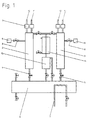
- a cooling device 1 comprises a first, for Recording of zeolite serving reactor 2 and a second, also for receiving zeolite serving reactor 3, which Valves 4 and 5 optionally with a certain amount of water Containing container 6 are connected. Belong to the container 6 Parts 7 of a heat exchanger, with the help of which in the container 6th resulting low temperature is used.
- Both reactors 2 and 3 are also at least via valves 8 a vacuum generator 9 connected.
- About supply and discharge Lines 10 and 11 or 12 and 13 can both reactors 2 and 3 be supplied with the necessary heat for the desorption process.
- the water vapor expelled from the zeolite passes through a closable outlet opening into a heat exchanger 14 condense there and is in a collection container 15 as Condensate collected before this is again placed in the container 6 becomes.
- the two reactors 2 and 3 are essentially the same designed and comprise, according to FIG. 2, an insulation 16 provided housing 17 with a bottom 18 and a lid 19. Der Bottom 18 has a suction opening 20 for the water vapor from the Container 6 on.
- the interior 21 of the housing 17 is located in the case in FIG. 2 and 3 shown embodiment containing several zeolite Inner container 22.
- Each inner container 22 has a length L, which in Compared to the dimensions of its cross section is very large and can be on the order of 1 to 5 to 1 to 10 or more.
- the inner container 22 is rod-shaped. He is preferably cylindrical and can basically in cross section also be polygonal.
- Each inner container 22 has a container wall 23, which is for air and water vapor is permeable.
- Container wall 23 made of a wire mesh 24, as shown in FIG. 4 is shown.
- the heating device 28 comprises a heating rod 29, which is expediently along the axis 30 of each inner container 22 extends.
- the heating element 29 can be an electrical heating element.
- the heating device 28 can also be a heating tube corresponding to the heating element 29, which is used to conduct a hot liquid - such as thermal oil - along the axis 30 of the inner container 22 is used.
- thermal conductors 31 are in the Zeolite 27 existing bed 26 arranged and with the Heating rod 29 or connected to the heating tube.
- the heat-conducting elements 31 are rib-shaped or disk-shaped.
- the heat-conducting elements 31 can also consist of one Copper wire mesh consist, or they consist of one Metal network that surrounds the heating rod 29 and is arranged in such a way that the zeolite 27 is largely positive in the metal network is stored.
- FIG. 3 shows a plurality of inner containers 22 in the housing 17 each spaced apart.
- the heating rods 29 and Heating pipes for the hot liquid / thermal oil are corresponding arranged rotationally symmetrical.
- Each on the front of the Housing 17 are the heating pipes with the aid of coupling pieces 33 or 34 as rotationally symmetrical as possible with each other and with the Lines 10 and 11 or 12 and 13 connected.
- the lines 10 and 11 or 12 and 13 serve as a flow or return line and are each on an end face 35 of the housing 17 to the in its Inside 21 located heating pipes or coupling pieces 33 connected.
- the two Figures 5 and 6 finally show one Thermally conductive element 40, the form-fitting a heating rod 29 or a Surrounds the heating tube and comprises rods 41 arranged in a star shape.
- bars 41 are at a short distance above one another arranged and outside with the aid of connecting pieces 42 connected with each other. Connect further connectors 43 Rods 41 in one plane, as shown in FIG. 5.
- the rods 41 and the connectors 42 and 43 of the Thermally conductive element 40 each consist of a good thermally conductive material and are therefore able to absorb the heat from to discharge the heating rod 29 to the outside on the zeolite located there.
- the dimensions of the heat-conducting element 40 are for this purpose Dimensions in the interior 25 of the inner container 22 customized.
Landscapes
- Engineering & Computer Science (AREA)
- Chemical & Material Sciences (AREA)
- Physics & Mathematics (AREA)
- Thermal Sciences (AREA)
- Analytical Chemistry (AREA)
- General Chemical & Material Sciences (AREA)
- Oil, Petroleum & Natural Gas (AREA)
- Chemical Kinetics & Catalysis (AREA)
- Mechanical Engineering (AREA)
- General Engineering & Computer Science (AREA)
- Sorption Type Refrigeration Machines (AREA)
Applications Claiming Priority (2)
| Application Number | Priority Date | Filing Date | Title |
|---|---|---|---|
| DE10015886 | 2000-03-30 | ||
| DE10015886A DE10015886A1 (de) | 2000-03-30 | 2000-03-30 | Reaktor für eine Kühleinrichtung |
Publications (2)
| Publication Number | Publication Date |
|---|---|
| EP1138367A2 true EP1138367A2 (fr) | 2001-10-04 |
| EP1138367A3 EP1138367A3 (fr) | 2002-11-20 |
Family
ID=7637014
Family Applications (1)
| Application Number | Title | Priority Date | Filing Date |
|---|---|---|---|
| EP01107112A Withdrawn EP1138367A3 (fr) | 2000-03-30 | 2001-03-22 | Réacteur pour un dispositif de refroidissement |
Country Status (3)
| Country | Link |
|---|---|
| US (1) | US20010041156A1 (fr) |
| EP (1) | EP1138367A3 (fr) |
| DE (1) | DE10015886A1 (fr) |
Cited By (1)
| Publication number | Priority date | Publication date | Assignee | Title |
|---|---|---|---|---|
| CN107543332A (zh) * | 2017-10-09 | 2018-01-05 | 广州市香港科大霍英东研究院 | 一种紧凑式吸附制冷系统 |
Families Citing this family (4)
| Publication number | Priority date | Publication date | Assignee | Title |
|---|---|---|---|---|
| DE102005001056B4 (de) * | 2005-01-07 | 2007-03-29 | Sortech Ag | Sorptionsspeicherelement und Verfahren zur dessen Herstellung |
| FR2884441B1 (fr) * | 2005-04-15 | 2007-06-01 | Syngas Entpr Unipersonnelle A | Dispositif d'epuration des gaz par adsorption |
| DE102008055699A1 (de) | 2007-11-09 | 2009-10-15 | Vaillant Gmbh | Sorber-Wärmetauscher einer Adsorptions-Wärmepumpe |
| DE102013223342A1 (de) * | 2013-11-15 | 2015-05-21 | Thyssenkrupp Marine Systems Gmbh | Unterseeboot mit einer CO2-Bindeeinrichtung |
Family Cites Families (22)
| Publication number | Priority date | Publication date | Assignee | Title |
|---|---|---|---|---|
| US1954056A (en) * | 1930-11-18 | 1934-04-10 | Chester F Hockley | Adsorber system |
| US2370643A (en) * | 1942-05-11 | 1945-03-06 | Kleen Refrigerator Inc | Refrigeration apparatus of the intermittent absorption or adsorption type |
| GB1572737A (en) * | 1977-01-17 | 1980-08-06 | Exxon France | Heat pump |
| DE3207656A1 (de) * | 1982-02-15 | 1983-08-25 | Hieronimi, Ulrich, 8000 München | Sorptionsapparate und verfahren fuer ihren betrieb |
| DE3342985A1 (de) * | 1983-11-28 | 1985-06-13 | Fritz Dipl.-Ing. Kaubek | Kontinuierlichwirkende sorptionsapparate und verfahren zu deren betrieb |
| FR2590356B1 (fr) * | 1985-11-19 | 1989-06-02 | Jeumont Schneider | Dispositif pour la production en continu de chaud et de froid |
| US5186020A (en) * | 1991-01-23 | 1993-02-16 | Rocky Research | Portable cooler |
| US5441716A (en) * | 1989-03-08 | 1995-08-15 | Rocky Research | Method and apparatus for achieving high reaction rates |
| US5477706A (en) * | 1991-11-19 | 1995-12-26 | Rocky Research | Heat transfer apparatus and methods for solid-vapor sorption systems |
| US5419156A (en) * | 1990-06-04 | 1995-05-30 | Aerojet-General Corporation | Regenerative sorption compressor assembly |
| JPH04141227A (ja) * | 1990-10-03 | 1992-05-14 | Nagaoka Kinmo Kk | ラジアルフロー式触媒充填塔における触媒保持方法および装置 |
| US5291942A (en) * | 1993-05-24 | 1994-03-08 | Gas Research Institute | Multiple stage sorption and desorption process and apparatus |
| WO1995014898A1 (fr) * | 1993-11-29 | 1995-06-01 | Mayekawa Mfg. Co., Ltd. | Appareil de refroidissement a adsorption, procede de commande de sa production de froid et echangeur thermique du type a aileron qui y est incorpore |
| GB9419202D0 (en) * | 1994-09-23 | 1994-11-09 | Univ Warwick | Thermal compressive device |
| JPH0999731A (ja) * | 1995-10-05 | 1997-04-15 | Denso Corp | 吸着式空気調和装置 |
| US5660049A (en) * | 1995-11-13 | 1997-08-26 | Erickson; Donald C. | Sorber with multiple cocurrent pressure equalized upflows |
| US5802870A (en) * | 1997-05-02 | 1998-09-08 | Uop Llc | Sorption cooling process and system |
| US6125649A (en) * | 1999-02-10 | 2000-10-03 | Chill-Can International, Inc. | Heat exchanger unit with conductive discs |
| AT411551B (de) * | 2000-04-17 | 2004-02-25 | Vaillant Gmbh | Adsorber-/desorber-wärmetauscher |
| DE10023650A1 (de) * | 2000-05-13 | 2001-11-22 | H & P Technologie Gmbh & Co Ge | Verfahren und Vorrichtung zum Kühlen |
| US6438992B1 (en) * | 2000-10-18 | 2002-08-27 | Thermal Products Development, Inc. | Evacuated sorbent assembly and cooling device incorporating same |
| US6601404B1 (en) * | 2001-08-17 | 2003-08-05 | Nanopore, Inc. | Cooling device |
-
2000
- 2000-03-30 DE DE10015886A patent/DE10015886A1/de not_active Withdrawn
-
2001
- 2001-03-22 EP EP01107112A patent/EP1138367A3/fr not_active Withdrawn
- 2001-03-30 US US09/823,913 patent/US20010041156A1/en not_active Abandoned
Cited By (1)
| Publication number | Priority date | Publication date | Assignee | Title |
|---|---|---|---|---|
| CN107543332A (zh) * | 2017-10-09 | 2018-01-05 | 广州市香港科大霍英东研究院 | 一种紧凑式吸附制冷系统 |
Also Published As
| Publication number | Publication date |
|---|---|
| US20010041156A1 (en) | 2001-11-15 |
| EP1138367A3 (fr) | 2002-11-20 |
| DE10015886A1 (de) | 2001-10-11 |
Similar Documents
| Publication | Publication Date | Title |
|---|---|---|
| DE2720120C2 (de) | Vorrichtung zur Behandlung eines organische Substanzen enthaltenden Gases mit Aktivkohle | |
| EP0143234B1 (fr) | Procédé pour traiter les résines échangeuses d'ions faiblement ou moyennement actives | |
| DE3003991C2 (de) | Kühleinrichtung mit einem Verdampfer, einem Kondersator sowie einem dehnbaren Flüssigkeitsbehälter | |
| DE2655936A1 (de) | Gas-abtrennsystem | |
| DE1767271B2 (de) | Einrichtung für die Kontaktierung von mindestens zwei Flüssigkeiten | |
| WO2010139599A2 (fr) | Appareil électro-ménager et dispositif d'élimination du calcaire de l'enceinte d'un tel appareil | |
| EP2447625A2 (fr) | Réacteur | |
| DE2744952C2 (de) | Solare Pumpanlage zum Pumpen von Flüssigkeiten | |
| DE10015886A1 (de) | Reaktor für eine Kühleinrichtung | |
| DE19929212C2 (de) | Verfahren und Vorrichtung zum Destillieren eines flüssigen Stoffs aus einer Lösung | |
| DE2622699A1 (de) | Speicherelement fuer ein sorptions- waermespeichersystem | |
| DE102012111744B4 (de) | Latentwärmespeicher und Heizung, Solarthermieanlage und Kältespeicher mit einem Latentwärmespeicher und Verfahren zum Speichern und Rückgewinnen von Wärmeenergie | |
| DE3236304C2 (de) | Absorber mit schwimmenden Füllkörpern | |
| DE3146902A1 (de) | Heizanlage | |
| DE2350068C3 (de) | Mehrstufenverdampfer | |
| DE2735924A1 (de) | Aufbau fuer transport und lagerung von radioaktiven kernbrennstoffelementen | |
| DE102009003912A1 (de) | Kocher für eine Diffusionsabsorptionsanlage | |
| DE941795C (de) | Gastrennanlage | |
| DE9404126U1 (de) | Vorrichtung zur Kälteerzeugung und Wärmespeicherung über Feststoffadsorption mittels Wasserdampf und heißen Gasen | |
| DE1551327B2 (de) | Absorptions-kuehlvorrichtung | |
| DE2848041C2 (de) | Rektifizierkolonne | |
| DE505267C (de) | Verfahren zur Kaelteerzeugung | |
| EP3120362B1 (fr) | Élément de refroidissement pour refroidir le liquide de refroidissement d'une piscine de refroidissement, système associé, piscine de refroidissement et installation nucléaire | |
| DE2734428C2 (de) | Behälter zur Speicherung von Flüssigkeiten | |
| AT139112B (de) | Vorrichtung zum Verteilen eines Mediums in einer eine Reaktionsvorrichtung füllenden Kontaktmasse. |
Legal Events
| Date | Code | Title | Description |
|---|---|---|---|
| PUAI | Public reference made under article 153(3) epc to a published international application that has entered the european phase |
Free format text: ORIGINAL CODE: 0009012 |
|
| AK | Designated contracting states |
Kind code of ref document: A2 Designated state(s): AT BE CH CY DE DK ES FI FR GB GR IE IT LI LU MC NL PT SE TR |
|
| AX | Request for extension of the european patent |
Free format text: AL;LT;LV;MK;RO;SI |
|
| PUAL | Search report despatched |
Free format text: ORIGINAL CODE: 0009013 |
|
| AK | Designated contracting states |
Kind code of ref document: A3 Designated state(s): AT BE CH CY DE DK ES FI FR GB GR IE IT LI LU MC NL PT SE TR |
|
| AX | Request for extension of the european patent |
Free format text: AL;LT;LV;MK;RO;SI |
|
| STAA | Information on the status of an ep patent application or granted ep patent |
Free format text: STATUS: THE APPLICATION HAS BEEN WITHDRAWN |
|
| RAP1 | Party data changed (applicant data changed or rights of an application transferred) |
Owner name: HAMMER, ROLF Owner name: PATZNER, NORBERT, DIPL.-ING., DIPL.-WIRTSCH.-ING. |
|
| 18W | Application withdrawn |
Effective date: 20030516 |