EP1138406B1 - Eine Presse mit einem hydraulischen Ziehkissen und mit einem System zur Steuerung der Presskraft und der Position des Blechhalters des Ziehkissens - Google Patents
Eine Presse mit einem hydraulischen Ziehkissen und mit einem System zur Steuerung der Presskraft und der Position des Blechhalters des Ziehkissens Download PDFInfo
- Publication number
- EP1138406B1 EP1138406B1 EP01500085A EP01500085A EP1138406B1 EP 1138406 B1 EP1138406 B1 EP 1138406B1 EP 01500085 A EP01500085 A EP 01500085A EP 01500085 A EP01500085 A EP 01500085A EP 1138406 B1 EP1138406 B1 EP 1138406B1
- Authority
- EP
- European Patent Office
- Prior art keywords
- cylinder
- control
- cushion
- force
- press
- Prior art date
- Legal status (The legal status is an assumption and is not a legal conclusion. Google has not performed a legal analysis and makes no representation as to the accuracy of the status listed.)
- Expired - Lifetime
Links
- 238000000034 method Methods 0.000 description 8
- 230000001133 acceleration Effects 0.000 description 5
- 230000001276 controlling effect Effects 0.000 description 2
- 230000000712 assembly Effects 0.000 description 1
- 238000000429 assembly Methods 0.000 description 1
- 238000010586 diagram Methods 0.000 description 1
- 230000000977 initiatory effect Effects 0.000 description 1
- 238000012423 maintenance Methods 0.000 description 1
- 230000001105 regulatory effect Effects 0.000 description 1
- 238000007493 shaping process Methods 0.000 description 1
Images


Classifications
-
- B—PERFORMING OPERATIONS; TRANSPORTING
- B21—MECHANICAL METAL-WORKING WITHOUT ESSENTIALLY REMOVING MATERIAL; PUNCHING METAL
- B21D—WORKING OR PROCESSING OF SHEET METAL OR METAL TUBES, RODS OR PROFILES WITHOUT ESSENTIALLY REMOVING MATERIAL; PUNCHING METAL
- B21D24/00—Special deep-drawing arrangements in, or in connection with, presses
- B21D24/04—Blank holders; Mounting means therefor
- B21D24/08—Pneumatically or hydraulically loaded blank holders
-
- B—PERFORMING OPERATIONS; TRANSPORTING
- B21—MECHANICAL METAL-WORKING WITHOUT ESSENTIALLY REMOVING MATERIAL; PUNCHING METAL
- B21D—WORKING OR PROCESSING OF SHEET METAL OR METAL TUBES, RODS OR PROFILES WITHOUT ESSENTIALLY REMOVING MATERIAL; PUNCHING METAL
- B21D24/00—Special deep-drawing arrangements in, or in connection with, presses
- B21D24/10—Devices controlling or operating blank holders independently, or in conjunction with dies
- B21D24/14—Devices controlling or operating blank holders independently, or in conjunction with dies pneumatically or hydraulically
Definitions
- the present invention relates to a press with a hydraulic cushions and a control system for controlling the force of the hydraulic cushion when a plate is drawn or stamped, according to the preamble of claim 1 (see for example JP-A-63 273 524).
- US-5746084 discloses a press on which a cylinder with two pressure chambers is added for pre-acceleration control, said control being carried out by drawing out oil from the lower chamber by means of using a proportional valve and a metering cylinder.
- the cushion comprises a pneumatic cylinder and a hydraulic cylinder, the pre-acceleration being controlled by way of the hydraulic cylinder.
- DE-3807683 describes a press that comprises a plurality of cylinder assemblies that include an axially arranged pressing cylinder and a lifting cylinder.
- the pressures of the pressing cylinders may be regulated individually by means of control elements and there is a control system for simultaneous movement of the lifting cylinders.
- the pressing cylinders are used for securing the plate during drawing and the lifting cylinders are used for raising the blank holder. This set-up permits control of cushion movement during the whole pressing process, the lifting cylinders being the ones that assist position control (during pre-acceleration, etc.) and the pressing cylinders being the ones that assist force control.
- the object of the invention is a press with a hydraulic cushion with a system for controlling the force and pad position thereof, as defined in the claims.
- the control system equipping the press enables the pad position and force to be controlled throughout the pressing process by means of the use of a single control element for each hydraulic cylinder.
- control element The function of said control element is to regulate the input and output of oil from the lower chamber of each hydraulic cylinder during pressing, both when position control is required and when force control is required.
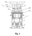
- the cushion 2 of the press 1 comprises a box 21 that rests on a plurality of hydraulic cylinders 3. There is one valve 7 per said cylinder 3.
- the slide 29 of the press 1 which has a reciprocating up and down movement, carries the upper half of the die 18 a , which, together with the lower half of the die 18 b , forms plate 19. Said plate 19 is pressed by the upper half of the die 18 a and the blank holder 20 during the shaping process, the effort of the cushion 2 being transmitted to the blank holder 20 by way of a plurality of pressure pins 30.
- each cylinder 3 has a rod 14 on which the box 21 rests and a piston 15 that defines an upper chamber 4 and a lower chamber 5.
- the position and force of each cylinder 3 in the course of the pressing process is controlled by means of a single control element 7 which regulates the pressure of the lower chamber 5 of each cylinder 3.
- the control element 7 is governed by a control unit 6 by way of a line 26.
- the control unit 6 receives information on the pressure in chambers 4 and 5 of each cylinder 3, on the position of the piston 15 of each cylinder 3, and on the position of slide 29 of the press 1.
- the information on the pressure in the chambers 4 and 5 is provided by the pressure transducers 8 and 9 by way of signals 22 and 23, respectively.
- the position transducers 10 and 11 supply, respectively, information on the position of the cylinder 3 (signal 24) and of the press 1 (signal 23).
- the control element 7 is a valve that regulates the input and output of oil in chamber 5 by offering resistance to its flow.
- the outlet of the control element 7 is connected to the lower chamber 5 and its inlets are connected to a pressure generator set 12 and to a tank 13. Furthermore, the upper chamber 4 is also connected to the pressure generator set 12.
- control unit 6 exchanges status information with the press 1 controller 17 (line 28) and it is communicated with a user interface unit 16 (by way of a line 27). This enables the user to set up the operating and control parameters conveniently, besides performing graphic presentations and storing different working parameters.
- FIG. 2 Although a single cylinder 3 is shown in FIG. 2, a plurality of cylinders 3 is normally used, so that there will be a valve 7, a pair of pressure transducers 8 and 9 and a position transformer 10 per cylinder 3.
- FIG. 3 shows some of the paths R that may be traversed by the cushion 2 in relation to the path P of the press 1 slide 29 during plate 19 pressing.
- These paths R are possible due to the different functions that may be performed by the control system that is the object of the invention. Said functions are, for instance, as follows:
Landscapes
- Engineering & Computer Science (AREA)
- Mechanical Engineering (AREA)
- Shaping Metal By Deep-Drawing, Or The Like (AREA)
- Control Of Presses (AREA)
Claims (2)
- Eine Presse mit einem hydraulischen Polster und einem Steuerungssystem zur Steuerung der Kraft des hydraulischen Polsters (2),
wobei das genannte Polster (2) zumindest einen Hydraulikzylinder (3) mit einer oberen Kammer (4) und einer unteren Kammer (5) aufweist und
das genannte Steuerungssystem eine Steuereinheit (6) und Mess- und Steuerungselements (7,8,9,10,11) umfasst, wobei die Mess- und Steuerungselemente Druckaufnehmer (8,9) umfassen, die mit jedem Zylinder (3) in Verbindung stehen, die Informationen über den Druck in den Kammern (4,5) liefern, wobei das Steuerungssystem auf jeden einzelnen Zylinder (3) einwirkt, wozu ein einziges Steuerungselement (7) pro Zylinder (3) eingesetzt wird, das durch die Steuereinheit (6) geregelt wird, die den Öleinlass und -ablauf in der unteren Kammer (5) eines jeden Zylinders (3) reguliert, wobei die obere Kammer (4) an ein Druckerzeugeraggregat (12) angeschlossen ist,
dadurch gekennzeichnet, dass jeder Zylinder (3) einen Lageaufnehmer (10) umfasst, wobei die Steuereinheit (6) ein Signal (24) von jedem Lageaufnehmer (10) empfängt, um die Lage eines jeden Zylinders (3) zu steuern, so dass sowohl die Lage als auch die Kraft auf dem Polster (2) durch Einwirken auf jeden einzelnen Zylinder (3)gesteuert werden. - Eine Presse nach Anspruch 1, wobei das Steuerungselement (7) ein Ventil ist, das den Öleinfluss und -ablauf in der unteren Kammer (5) regelt, indem es Widerstand gegen seinen Fluss bietet, wobei der Ausgang an die genannte untere Kammer (5) und seine Eingänge an ein Druckerzeugeraggregat (12) und an einen Behälter (13) angeschlossen sind.
Applications Claiming Priority (2)
| Application Number | Priority Date | Filing Date | Title |
|---|---|---|---|
| ES200000793 | 2000-03-30 | ||
| ES200000793A ES2190833B1 (es) | 2000-03-30 | 2000-03-30 | Prensa con cojin hidraulico con sistema de control de fuerza y posicion. |
Publications (3)
| Publication Number | Publication Date |
|---|---|
| EP1138406A2 EP1138406A2 (de) | 2001-10-04 |
| EP1138406A3 EP1138406A3 (de) | 2003-05-21 |
| EP1138406B1 true EP1138406B1 (de) | 2005-07-27 |
Family
ID=8492951
Family Applications (1)
| Application Number | Title | Priority Date | Filing Date |
|---|---|---|---|
| EP01500085A Expired - Lifetime EP1138406B1 (de) | 2000-03-30 | 2001-03-29 | Eine Presse mit einem hydraulischen Ziehkissen und mit einem System zur Steuerung der Presskraft und der Position des Blechhalters des Ziehkissens |
Country Status (4)
| Country | Link |
|---|---|
| EP (1) | EP1138406B1 (de) |
| AT (1) | ATE300370T1 (de) |
| DE (1) | DE60112154T2 (de) |
| ES (2) | ES2190833B1 (de) |
Families Citing this family (4)
| Publication number | Priority date | Publication date | Assignee | Title |
|---|---|---|---|---|
| DE10336279A1 (de) | 2003-08-07 | 2005-03-03 | Bosch Rexroth Ag | Einrichtung zur Steuerung des Ziehvorgangs bei einer Transferpresse |
| EP2712688B1 (de) | 2012-09-28 | 2020-12-02 | Siemens Aktiengesellschaft | Ziehkissenantrieb und Betriebsverfahren eines Ziehkissenantriebes |
| JP6702004B2 (ja) * | 2016-03-04 | 2020-05-27 | 日本製鉄株式会社 | ホットスタンプ成形品の製造方法および製造装置 |
| WO2019049322A1 (ja) | 2017-09-08 | 2019-03-14 | 新日鐵住金株式会社 | ホットスタンプ成形品、その製造方法および製造装置 |
Family Cites Families (4)
| Publication number | Priority date | Publication date | Assignee | Title |
|---|---|---|---|---|
| DD208094A1 (de) * | 1981-10-21 | 1984-03-28 | Gregor Geist | Ziehkissen fuer pressen |
| DE3476524D1 (en) * | 1984-06-29 | 1989-03-09 | Schuler Gmbh L | Drawing device in a press |
| JPS63273524A (ja) * | 1987-05-01 | 1988-11-10 | Ishikawajima Harima Heavy Ind Co Ltd | ダイクッション制御方法 |
| EP0417754B1 (de) * | 1989-09-12 | 1993-09-08 | Maschinenfabrik Müller-Weingarten AG | Mechanische oder hydraulische Presse mit Zieheinrichtung oder Ziehstufe einer Stufenpresse |
-
2000
- 2000-03-30 ES ES200000793A patent/ES2190833B1/es not_active Expired - Fee Related
-
2001
- 2001-03-29 EP EP01500085A patent/EP1138406B1/de not_active Expired - Lifetime
- 2001-03-29 DE DE60112154T patent/DE60112154T2/de not_active Expired - Fee Related
- 2001-03-29 ES ES01500085T patent/ES2244574T3/es not_active Expired - Lifetime
- 2001-03-29 AT AT01500085T patent/ATE300370T1/de not_active IP Right Cessation
Also Published As
| Publication number | Publication date |
|---|---|
| EP1138406A2 (de) | 2001-10-04 |
| ATE300370T1 (de) | 2005-08-15 |
| ES2190833A1 (es) | 2003-08-16 |
| DE60112154T2 (de) | 2006-05-24 |
| ES2244574T3 (es) | 2005-12-16 |
| EP1138406A3 (de) | 2003-05-21 |
| DE60112154D1 (de) | 2005-09-01 |
| ES2190833B1 (es) | 2004-07-01 |
Similar Documents
| Publication | Publication Date | Title |
|---|---|---|
| US2192778A (en) | Drawing press | |
| US5735201A (en) | Apparatus including mutually communicating hydraulic cylinders for even distribution of blank-holding force on pressing machine | |
| DE69313585T2 (de) | Ziehkissen und Verfahren zur Optimierung dessen Zylinderstiftendrucks | |
| US4635466A (en) | Die cushion apparatus for use in a press machine | |
| US7406851B2 (en) | Die cushion controlling apparatus and die cushion controlling method | |
| US10603709B2 (en) | Die cushion device | |
| US4229965A (en) | Hydraulic circuit of a hydromechanical drawing press | |
| JP6185973B2 (ja) | プレス機械のスライドクッション装置 | |
| US3707866A (en) | Machines for forming a workpiece between two ram heads | |
| EP0424122B1 (de) | Gesenkpolstereinrichtung für Presse | |
| EP1138406B1 (de) | Eine Presse mit einem hydraulischen Ziehkissen und mit einem System zur Steuerung der Presskraft und der Position des Blechhalters des Ziehkissens | |
| EP0744230B1 (de) | Verfahren und Vorrichtung zum Formen eines Bleches, wobei die Druckwange von zwischen dem Stempel und der Druckwange angeordneten Stossdämpfern abgesenkt wird, bevor das Blech zwischen dem Stempel und dem Blechgegenhalter gehalten wird | |
| US4370878A (en) | Workpiece ejector system for presses | |
| US10780485B2 (en) | Die cushion device | |
| GB2038222A (en) | Shock damping system/shearing tool assembly for presses | |
| GB2197813A (en) | Controlling or adjusting blank holder force during a drawing process | |
| US5960665A (en) | Drawing device for drawing presses | |
| US4212185A (en) | Hydraulic press system | |
| US6237381B1 (en) | Power press ram force modulation and apparatus for use therewith | |
| EP1445041B1 (de) | Vorrichtung zur Erfassung der Stempelposition in einer Metallblech-Stanzmaschine mit mehreren Stempeln | |
| DE10314302B3 (de) | Hydraulische Antriebsvorrichtung, Verfahren zum Betreiben einer hydraulischen Antriebsvorrichtung | |
| US20020023476A1 (en) | Power press | |
| US1936410A (en) | Metal drawing press | |
| JP3107985B2 (ja) | 油圧プレスの加圧力制御装置 | |
| DE19541693A1 (de) | Einrichtung zur Steuerung und Regelung des Druckes in hydraulischen Ziehkissen von Pressen |
Legal Events
| Date | Code | Title | Description |
|---|---|---|---|
| PUAI | Public reference made under article 153(3) epc to a published international application that has entered the european phase |
Free format text: ORIGINAL CODE: 0009012 |
|
| AK | Designated contracting states |
Kind code of ref document: A2 Designated state(s): AT BE CH CY DE DK ES FI FR GB GR IE IT LI LU MC NL PT SE TR |
|
| AX | Request for extension of the european patent |
Free format text: AL;LT;LV;MK;RO;SI |
|
| PUAL | Search report despatched |
Free format text: ORIGINAL CODE: 0009013 |
|
| AK | Designated contracting states |
Designated state(s): AT BE CH CY DE DK ES FI FR GB GR IE IT LI LU MC NL PT SE TR |
|
| AX | Request for extension of the european patent |
Extension state: AL LT LV MK RO SI |
|
| 17P | Request for examination filed |
Effective date: 20031020 |
|
| AKX | Designation fees paid |
Designated state(s): AT BE CH CY DE DK ES FI FR GB GR IE IT LI LU MC NL PT SE TR |
|
| 17Q | First examination report despatched |
Effective date: 20040305 |
|
| GRAP | Despatch of communication of intention to grant a patent |
Free format text: ORIGINAL CODE: EPIDOSNIGR1 |
|
| RAP1 | Party data changed (applicant data changed or rights of an application transferred) |
Owner name: FAGOR, S.COOP |
|
| GRAS | Grant fee paid |
Free format text: ORIGINAL CODE: EPIDOSNIGR3 |
|
| GRAA | (expected) grant |
Free format text: ORIGINAL CODE: 0009210 |
|
| AK | Designated contracting states |
Kind code of ref document: B1 Designated state(s): AT BE CH CY DE DK ES FI FR GB GR IE IT LI LU MC NL PT SE TR |
|
| PG25 | Lapsed in a contracting state [announced via postgrant information from national office to epo] |
Ref country code: LI Free format text: LAPSE BECAUSE OF FAILURE TO SUBMIT A TRANSLATION OF THE DESCRIPTION OR TO PAY THE FEE WITHIN THE PRESCRIBED TIME-LIMIT Effective date: 20050727 Ref country code: AT Free format text: LAPSE BECAUSE OF FAILURE TO SUBMIT A TRANSLATION OF THE DESCRIPTION OR TO PAY THE FEE WITHIN THE PRESCRIBED TIME-LIMIT Effective date: 20050727 Ref country code: FI Free format text: LAPSE BECAUSE OF FAILURE TO SUBMIT A TRANSLATION OF THE DESCRIPTION OR TO PAY THE FEE WITHIN THE PRESCRIBED TIME-LIMIT Effective date: 20050727 Ref country code: BE Free format text: LAPSE BECAUSE OF FAILURE TO SUBMIT A TRANSLATION OF THE DESCRIPTION OR TO PAY THE FEE WITHIN THE PRESCRIBED TIME-LIMIT Effective date: 20050727 Ref country code: NL Free format text: LAPSE BECAUSE OF FAILURE TO SUBMIT A TRANSLATION OF THE DESCRIPTION OR TO PAY THE FEE WITHIN THE PRESCRIBED TIME-LIMIT Effective date: 20050727 Ref country code: CH Free format text: LAPSE BECAUSE OF FAILURE TO SUBMIT A TRANSLATION OF THE DESCRIPTION OR TO PAY THE FEE WITHIN THE PRESCRIBED TIME-LIMIT Effective date: 20050727 Ref country code: TR Free format text: LAPSE BECAUSE OF FAILURE TO SUBMIT A TRANSLATION OF THE DESCRIPTION OR TO PAY THE FEE WITHIN THE PRESCRIBED TIME-LIMIT Effective date: 20050727 |
|
| REG | Reference to a national code |
Ref country code: GB Ref legal event code: FG4D |
|
| REG | Reference to a national code |
Ref country code: CH Ref legal event code: EP |
|
| REG | Reference to a national code |
Ref country code: IE Ref legal event code: FG4D |
|
| REF | Corresponds to: |
Ref document number: 60112154 Country of ref document: DE Date of ref document: 20050901 Kind code of ref document: P |
|
| PG25 | Lapsed in a contracting state [announced via postgrant information from national office to epo] |
Ref country code: SE Free format text: LAPSE BECAUSE OF FAILURE TO SUBMIT A TRANSLATION OF THE DESCRIPTION OR TO PAY THE FEE WITHIN THE PRESCRIBED TIME-LIMIT Effective date: 20051027 Ref country code: GR Free format text: LAPSE BECAUSE OF FAILURE TO SUBMIT A TRANSLATION OF THE DESCRIPTION OR TO PAY THE FEE WITHIN THE PRESCRIBED TIME-LIMIT Effective date: 20051027 Ref country code: DK Free format text: LAPSE BECAUSE OF FAILURE TO SUBMIT A TRANSLATION OF THE DESCRIPTION OR TO PAY THE FEE WITHIN THE PRESCRIBED TIME-LIMIT Effective date: 20051027 |
|
| REG | Reference to a national code |
Ref country code: ES Ref legal event code: FG2A Ref document number: 2244574 Country of ref document: ES Kind code of ref document: T3 |
|
| PG25 | Lapsed in a contracting state [announced via postgrant information from national office to epo] |
Ref country code: PT Free format text: LAPSE BECAUSE OF FAILURE TO SUBMIT A TRANSLATION OF THE DESCRIPTION OR TO PAY THE FEE WITHIN THE PRESCRIBED TIME-LIMIT Effective date: 20051227 |
|
| REG | Reference to a national code |
Ref country code: CH Ref legal event code: PL |
|
| NLV1 | Nl: lapsed or annulled due to failure to fulfill the requirements of art. 29p and 29m of the patents act | ||
| PG25 | Lapsed in a contracting state [announced via postgrant information from national office to epo] |
Ref country code: IE Free format text: LAPSE BECAUSE OF NON-PAYMENT OF DUE FEES Effective date: 20060329 |
|
| PG25 | Lapsed in a contracting state [announced via postgrant information from national office to epo] |
Ref country code: LU Free format text: LAPSE BECAUSE OF NON-PAYMENT OF DUE FEES Effective date: 20060331 Ref country code: MC Free format text: LAPSE BECAUSE OF NON-PAYMENT OF DUE FEES Effective date: 20060331 |
|
| ET | Fr: translation filed | ||
| PLBE | No opposition filed within time limit |
Free format text: ORIGINAL CODE: 0009261 |
|
| STAA | Information on the status of an ep patent application or granted ep patent |
Free format text: STATUS: NO OPPOSITION FILED WITHIN TIME LIMIT |
|
| 26N | No opposition filed |
Effective date: 20060428 |
|
| REG | Reference to a national code |
Ref country code: IE Ref legal event code: MM4A |
|
| PGFP | Annual fee paid to national office [announced via postgrant information from national office to epo] |
Ref country code: ES Payment date: 20080312 Year of fee payment: 8 |
|
| PGFP | Annual fee paid to national office [announced via postgrant information from national office to epo] |
Ref country code: GB Payment date: 20080320 Year of fee payment: 8 Ref country code: IT Payment date: 20080326 Year of fee payment: 8 |
|
| PGFP | Annual fee paid to national office [announced via postgrant information from national office to epo] |
Ref country code: DE Payment date: 20080321 Year of fee payment: 8 Ref country code: FR Payment date: 20080314 Year of fee payment: 8 |
|
| PG25 | Lapsed in a contracting state [announced via postgrant information from national office to epo] |
Ref country code: CY Free format text: LAPSE BECAUSE OF FAILURE TO SUBMIT A TRANSLATION OF THE DESCRIPTION OR TO PAY THE FEE WITHIN THE PRESCRIBED TIME-LIMIT Effective date: 20050727 |
|
| GBPC | Gb: european patent ceased through non-payment of renewal fee |
Effective date: 20090329 |
|
| REG | Reference to a national code |
Ref country code: FR Ref legal event code: ST Effective date: 20091130 |
|
| PG25 | Lapsed in a contracting state [announced via postgrant information from national office to epo] |
Ref country code: DE Free format text: LAPSE BECAUSE OF NON-PAYMENT OF DUE FEES Effective date: 20091001 |
|
| PG25 | Lapsed in a contracting state [announced via postgrant information from national office to epo] |
Ref country code: GB Free format text: LAPSE BECAUSE OF NON-PAYMENT OF DUE FEES Effective date: 20090329 Ref country code: FR Free format text: LAPSE BECAUSE OF NON-PAYMENT OF DUE FEES Effective date: 20091123 |
|
| REG | Reference to a national code |
Ref country code: ES Ref legal event code: FD2A Effective date: 20090330 |
|
| PG25 | Lapsed in a contracting state [announced via postgrant information from national office to epo] |
Ref country code: ES Free format text: LAPSE BECAUSE OF NON-PAYMENT OF DUE FEES Effective date: 20090330 |
|
| PG25 | Lapsed in a contracting state [announced via postgrant information from national office to epo] |
Ref country code: IT Free format text: LAPSE BECAUSE OF NON-PAYMENT OF DUE FEES Effective date: 20090329 |