EP1138425A1 - Appareil pour couper des tubes - Google Patents
Appareil pour couper des tubes Download PDFInfo
- Publication number
- EP1138425A1 EP1138425A1 EP01104706A EP01104706A EP1138425A1 EP 1138425 A1 EP1138425 A1 EP 1138425A1 EP 01104706 A EP01104706 A EP 01104706A EP 01104706 A EP01104706 A EP 01104706A EP 1138425 A1 EP1138425 A1 EP 1138425A1
- Authority
- EP
- European Patent Office
- Prior art keywords
- gear
- cutting device
- pipe
- transmission gear
- pipe cutting
- Prior art date
- Legal status (The legal status is an assumption and is not a legal conclusion. Google has not performed a legal analysis and makes no representation as to the accuracy of the status listed.)
- Granted
Links
- 238000005520 cutting process Methods 0.000 claims abstract description 33
- 230000005540 biological transmission Effects 0.000 claims abstract description 24
- 238000011144 upstream manufacturing Methods 0.000 claims description 3
- 238000000926 separation method Methods 0.000 description 3
- 230000008878 coupling Effects 0.000 description 1
- 238000010168 coupling process Methods 0.000 description 1
- 238000005859 coupling reaction Methods 0.000 description 1
- 238000003754 machining Methods 0.000 description 1
- 238000000034 method Methods 0.000 description 1
Images


Classifications
-
- B—PERFORMING OPERATIONS; TRANSPORTING
- B23—MACHINE TOOLS; METAL-WORKING NOT OTHERWISE PROVIDED FOR
- B23D—PLANING; SLOTTING; SHEARING; BROACHING; SAWING; FILING; SCRAPING; LIKE OPERATIONS FOR WORKING METAL BY REMOVING MATERIAL, NOT OTHERWISE PROVIDED FOR
- B23D21/00—Machines or devices for shearing or cutting tubes
- B23D21/06—Hand-operated tube-cutters
- B23D21/08—Hand-operated tube-cutters with cutting wheels
-
- B—PERFORMING OPERATIONS; TRANSPORTING
- B23—MACHINE TOOLS; METAL-WORKING NOT OTHERWISE PROVIDED FOR
- B23D—PLANING; SLOTTING; SHEARING; BROACHING; SAWING; FILING; SCRAPING; LIKE OPERATIONS FOR WORKING METAL BY REMOVING MATERIAL, NOT OTHERWISE PROVIDED FOR
- B23D21/00—Machines or devices for shearing or cutting tubes
- B23D21/04—Tube-severing machines with rotating tool-carrier
Definitions
- the invention relates to a pipe cutting device according to the preamble of Claim 1.
- pipe separation devices are known in which the separation device is guided around the pipe to be separated by means of a drive.
- the safety aspects are a disadvantage of the known pipe cutting devices. Especially with large pipe dimensions, both in relation to the Pipe diameter as well as wall thickness, are larger drives as well Tools required to make the device heavier. A manual one Due to ergonomic reasons, actuation can be easier Accidents or damage to tools and machines. Furthermore, it can be disadvantageous that the pipe cutting device in both Swings out directions uncontrollably.
- the transmission gear has a spur gear cooperating with a crown gear.
- the spur gear is a freewheel gear upstream.
- the freewheel gear prevents an incorrect feed direction. It is only possible to work in the desired direction of the tool. With this The desired security has been achieved.
- a worm gear is advantageously connected upstream of the spur gear.
- the worm gear offers a functionally reliable locking function, whereby for example a manual movement of the drive and thus the Tool in the wrong direction is prevented.
- the machining process can on the one hand via an actuating device and on the other hand done mechanically via a drive motor, the Actuating device suitably attached to the transmission gear Hand crank or a handwheel can be.
- the transmission gear is preferably fixed to the workpiece clamping device on the bearing bracket for the rotating body stored in it connected.
- the transmission gear can pivot in the position - or be rotatably connected with respect to the workpiece jig.
- the transmission gear can pivot in the position - or be rotatably connected with respect to the workpiece jig.
- the transmission gear swivel with the actuators in relation to the bearing bracket - and then lockable.
- the transmission gear is advantageously driven by means of a flexible shaft.
- the drive of the transmission gear is not directly involved the transmission gear is coupled, but at the workbench or at the fixed bearing bracket etc. is attached.
- the coupling could the drive to the transmission gear, for example via a flexible shaft or in any other similar way.
- FIG. 1 shows a three-dimensional representation of the pipe cutting device according to the invention
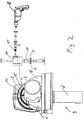
- Figure 2 shows the pipe cutting device with freewheel and worm gear
- Figure 3 is a rear view of the pipe cutting device.
- the drive 6 with the tool 5 is over the axis 2 of the pipe to be separated, clamped in the jaws 16 3 rotatably mounted on the bearing bracket 14.
- the tool 5 is by means of a slide to the workpiece 3 to be separated via a stroke curve in performed in a known manner, such as in DE AS 1 171 241 is described.
- the housing 17 of the transmission 7 is fixed or pivotable (not in shown in the drawing) connected to the bearing bracket 14.
- One here as Hand crank trained actuator 12 is via gear devices connected to the spur gear 9, not shown in Figure 1, for actuation.
- the spur gear 9 engages in the crown gear 8 for the pivotable actuation of the Separator 4 a.
- FIG. 2 The details in this embodiment are shown in FIG. 2, in which the Housing 17 for the transmission gear 7 detached from the bearing bracket 14 for the crown wheel 8 is shown.
- a transmission gear 7 is located next to the spur gear 9 Freewheel gear 10.
- the freewheel gear is used to prevent the wrong one Feed direction of the cutting tool 5.
- a worm gear 11 which acts self-locking for functional safety.
- a manual operation 12 is provided in Figure 1 with the Worm gear 11 .
- Figure 2 is one mechanical drive option, for example a cordless screwdriver 18 shown.
- the cordless screwdriver can be connected directly to the worm gear 11 be connected.
- the connection via a flexible is also not conceivable Shown drive shaft when, for example, for spatial reasons mechanical drive is provided in another location.
- the actual separating device 4 is on the one hand only in the desired direction of rotation via the actuating device 12 in the direction of arrow 19 or on the other hand directly by swiveling the drive 6 in desired direction possible.
- the opposite direction is due the freewheel and the worm gear prevented.
- the separator 4 is desired in the opposite direction to move to arrow 20. This is done by appropriate simultaneous actuation of the Device 12 against arrow 19 and a pivoting of the drive possible against arrow direction 20. Since this is a simultaneity of Movement is required, an uncontrolled force can be exerted on the rotating body 15 do not work, which ensures additional security.
- Pipe cutting device can be used as tools.
- a pipe to be treated is clamped in the clamping device. This is followed by setting the dimensions, i.e. the action group of the Saw blade. Then the drive 6 is switched on.
- the tool delivery takes place automatically via a stroke curve.
- the feed movement can be done manually take place via the actuating device 12 or by motor via a drive 18.
- the feed movement can also be used, for example, in the case of small pipe dimensions by pulling the drive 6. Because of the freewheel gear 10, the manual operation is prevented from running.
- the tool delivery is automatically retracted.
- the saw motor can be switched off.
Landscapes
- Engineering & Computer Science (AREA)
- Mechanical Engineering (AREA)
- Sawing (AREA)
- Turning (AREA)
- Accessories And Tools For Shearing Machines (AREA)
Applications Claiming Priority (2)
| Application Number | Priority Date | Filing Date | Title |
|---|---|---|---|
| DE10014777A DE10014777A1 (de) | 2000-03-27 | 2000-03-27 | Rohrtrennvorrichtung |
| DE10014777 | 2000-03-27 |
Publications (2)
| Publication Number | Publication Date |
|---|---|
| EP1138425A1 true EP1138425A1 (fr) | 2001-10-04 |
| EP1138425B1 EP1138425B1 (fr) | 2005-07-20 |
Family
ID=7636278
Family Applications (1)
| Application Number | Title | Priority Date | Filing Date |
|---|---|---|---|
| EP01104706A Expired - Lifetime EP1138425B1 (fr) | 2000-03-27 | 2001-02-26 | Appareil pour couper des tubes |
Country Status (4)
| Country | Link |
|---|---|
| US (1) | US6568086B2 (fr) |
| EP (1) | EP1138425B1 (fr) |
| AT (1) | ATE299773T1 (fr) |
| DE (2) | DE10014777A1 (fr) |
Cited By (2)
| Publication number | Priority date | Publication date | Assignee | Title |
|---|---|---|---|---|
| WO2009137214A1 (fr) * | 2008-05-06 | 2009-11-12 | Illinois Tool Works Inc. | Dispositif de travail de tube se présentant sous la forme d'un coupe-tube ou d'un dispositif de travail d'extrémité de tube |
| US10442017B2 (en) * | 2016-06-16 | 2019-10-15 | Sonja Maria Bilz | Support peg holder for a pipe cutter |
Families Citing this family (5)
| Publication number | Priority date | Publication date | Assignee | Title |
|---|---|---|---|---|
| DE10352890B4 (de) * | 2003-11-10 | 2007-05-31 | Illinois Tool Works Inc., Glenview | Kreissägevorrichtung zum Abtrennen von Rohren |
| DE102007008355B4 (de) * | 2007-02-20 | 2015-12-24 | Illinois Tool Works Inc. | Rohrtrennvorrichtung |
| DE112008000686B4 (de) | 2007-03-15 | 2016-07-28 | Milwaukee Electric Tool Corp. | Rohrschneider |
| WO2009070357A1 (fr) | 2007-11-28 | 2009-06-04 | Milwaukee Electric Tool Corporation | Coupe-tube |
| CN103111541B (zh) * | 2013-02-21 | 2015-10-28 | 扬州天禾科技实业有限公司 | 齿轮整形自动定位送料装置 |
Citations (3)
| Publication number | Priority date | Publication date | Assignee | Title |
|---|---|---|---|---|
| US4890385A (en) * | 1988-02-29 | 1990-01-02 | Tri Tool Inc. | Automatic feed system for a tube cutter |
| US4953292A (en) * | 1989-09-26 | 1990-09-04 | Tobey Billy D | Hand-holdable tube cutting device |
| US5495672A (en) * | 1994-08-29 | 1996-03-05 | The Pullman Co. | Tube cutter |
Family Cites Families (3)
| Publication number | Priority date | Publication date | Assignee | Title |
|---|---|---|---|---|
| US722843A (en) * | 1902-02-05 | 1903-03-17 | Wilhelm Hoepflinger | Machine for cutting iron bars or tubes. |
| DE921963C (de) * | 1951-06-13 | 1955-01-07 | Wolfram Thevessen | Vorrichtung zum Gewindeschneiden an und Zerschneiden von Rohren |
| DE1171241B (de) | 1959-04-07 | 1964-05-27 | Fischer Ag Georg | Rohrtrennvorrichtung, insbesondere fuer Montagezwecke |
-
2000
- 2000-03-27 DE DE10014777A patent/DE10014777A1/de not_active Withdrawn
-
2001
- 2001-02-26 DE DE50106750T patent/DE50106750D1/de not_active Expired - Lifetime
- 2001-02-26 EP EP01104706A patent/EP1138425B1/fr not_active Expired - Lifetime
- 2001-02-26 AT AT01104706T patent/ATE299773T1/de not_active IP Right Cessation
- 2001-03-26 US US09/817,665 patent/US6568086B2/en not_active Expired - Fee Related
Patent Citations (3)
| Publication number | Priority date | Publication date | Assignee | Title |
|---|---|---|---|---|
| US4890385A (en) * | 1988-02-29 | 1990-01-02 | Tri Tool Inc. | Automatic feed system for a tube cutter |
| US4953292A (en) * | 1989-09-26 | 1990-09-04 | Tobey Billy D | Hand-holdable tube cutting device |
| US5495672A (en) * | 1994-08-29 | 1996-03-05 | The Pullman Co. | Tube cutter |
Cited By (2)
| Publication number | Priority date | Publication date | Assignee | Title |
|---|---|---|---|---|
| WO2009137214A1 (fr) * | 2008-05-06 | 2009-11-12 | Illinois Tool Works Inc. | Dispositif de travail de tube se présentant sous la forme d'un coupe-tube ou d'un dispositif de travail d'extrémité de tube |
| US10442017B2 (en) * | 2016-06-16 | 2019-10-15 | Sonja Maria Bilz | Support peg holder for a pipe cutter |
Also Published As
| Publication number | Publication date |
|---|---|
| ATE299773T1 (de) | 2005-08-15 |
| US6568086B2 (en) | 2003-05-27 |
| EP1138425B1 (fr) | 2005-07-20 |
| DE10014777A1 (de) | 2001-10-04 |
| US20010023540A1 (en) | 2001-09-27 |
| DE50106750D1 (de) | 2005-08-25 |
Similar Documents
| Publication | Publication Date | Title |
|---|---|---|
| DE2524634C2 (de) | Rohrbearbeitungsmaschine | |
| DE19951658A1 (de) | Werkzeughalter | |
| DE2204566A1 (de) | Schneidemaschine und schneidverfahren, insbesondere zum schneiden von rohren | |
| DE4236347C2 (de) | Längsschneideinrichtung | |
| DE69623630T2 (de) | Werkzeug zum bearbeiten von rohrenden | |
| EP0949021B1 (fr) | Dispositif pour le formage de fil ayant un dispositif de freinage de fil | |
| DE69006207T2 (de) | Futter für Gewindeschneidmaschine. | |
| EP1138425B1 (fr) | Appareil pour couper des tubes | |
| DE10352890A1 (de) | Kreissägevorrichtung zum Abtrennen von Rohren | |
| DE1810052B2 (de) | Vorrichtung zum Durchschneiden von kontinuierlich zugeführten Rohren | |
| DE2946307C2 (de) | Tragbares Gerät zum Gewindeschneiden o.dgl. | |
| DE1552250B2 (de) | Formdrehautomat | |
| DE19920099B4 (de) | Positioniervorrichtung für Sägeblätter | |
| DE19612246A1 (de) | Holzbearbeitungsmaschine | |
| EP1393870B1 (fr) | Machine de fendage de bois | |
| EP0438997A2 (fr) | Dispositif de manipulation pour machine | |
| DE202020101282U1 (de) | Schälvorrichtung für Schläuche | |
| DE69008347T2 (de) | Rillenwalzvorrichtung. | |
| DE102019003737B3 (de) | Hand-Werkzeugmaschine | |
| DE2743151A1 (de) | Werkzeug zum schneiden von rohren, insbesondere kunststoffrohren | |
| DE138699C (fr) | ||
| DE8408651U1 (de) | Raeumgeraet | |
| DE1901170C3 (de) | Formdrehautomat zur Bearbeitung draht- oder stangenförmigen Werkstoffs | |
| DE102024124600A1 (de) | Elektrische Bearbeitungsmaschine, insbesondere Zugsäge | |
| DE4035094A1 (de) | Vorrichtung zum verdrillen von bindedraht fuer eine drahtbindemaschine |
Legal Events
| Date | Code | Title | Description |
|---|---|---|---|
| PUAI | Public reference made under article 153(3) epc to a published international application that has entered the european phase |
Free format text: ORIGINAL CODE: 0009012 |
|
| AK | Designated contracting states |
Kind code of ref document: A1 Designated state(s): AT BE CH CY DE DK ES FI FR GB GR IE IT LI LU MC NL PT SE TR |
|
| AX | Request for extension of the european patent |
Free format text: AL;LT;LV;MK;RO;SI |
|
| 17P | Request for examination filed |
Effective date: 20020114 |
|
| AKX | Designation fees paid |
Free format text: AT BE CH CY DE DK ES FI FR GB GR IE IT LI LU MC NL PT SE TR |
|
| 17Q | First examination report despatched |
Effective date: 20040917 |
|
| GRAP | Despatch of communication of intention to grant a patent |
Free format text: ORIGINAL CODE: EPIDOSNIGR1 |
|
| GRAS | Grant fee paid |
Free format text: ORIGINAL CODE: EPIDOSNIGR3 |
|
| GRAA | (expected) grant |
Free format text: ORIGINAL CODE: 0009210 |
|
| AK | Designated contracting states |
Kind code of ref document: B1 Designated state(s): AT BE CH CY DE DK ES FI FR GB GR IE IT LI LU MC NL PT SE TR |
|
| PG25 | Lapsed in a contracting state [announced via postgrant information from national office to epo] |
Ref country code: FI Free format text: LAPSE BECAUSE OF FAILURE TO SUBMIT A TRANSLATION OF THE DESCRIPTION OR TO PAY THE FEE WITHIN THE PRESCRIBED TIME-LIMIT Effective date: 20050720 Ref country code: GB Free format text: LAPSE BECAUSE OF FAILURE TO SUBMIT A TRANSLATION OF THE DESCRIPTION OR TO PAY THE FEE WITHIN THE PRESCRIBED TIME-LIMIT Effective date: 20050720 Ref country code: IE Free format text: LAPSE BECAUSE OF FAILURE TO SUBMIT A TRANSLATION OF THE DESCRIPTION OR TO PAY THE FEE WITHIN THE PRESCRIBED TIME-LIMIT Effective date: 20050720 Ref country code: TR Free format text: LAPSE BECAUSE OF FAILURE TO SUBMIT A TRANSLATION OF THE DESCRIPTION OR TO PAY THE FEE WITHIN THE PRESCRIBED TIME-LIMIT Effective date: 20050720 Ref country code: NL Free format text: LAPSE BECAUSE OF FAILURE TO SUBMIT A TRANSLATION OF THE DESCRIPTION OR TO PAY THE FEE WITHIN THE PRESCRIBED TIME-LIMIT Effective date: 20050720 |
|
| REG | Reference to a national code |
Ref country code: GB Ref legal event code: FG4D Free format text: NOT ENGLISH |
|
| REG | Reference to a national code |
Ref country code: CH Ref legal event code: EP |
|
| REG | Reference to a national code |
Ref country code: IE Ref legal event code: FG4D Free format text: LANGUAGE OF EP DOCUMENT: GERMAN |
|
| REF | Corresponds to: |
Ref document number: 50106750 Country of ref document: DE Date of ref document: 20050825 Kind code of ref document: P |
|
| PG25 | Lapsed in a contracting state [announced via postgrant information from national office to epo] |
Ref country code: GR Free format text: LAPSE BECAUSE OF FAILURE TO SUBMIT A TRANSLATION OF THE DESCRIPTION OR TO PAY THE FEE WITHIN THE PRESCRIBED TIME-LIMIT Effective date: 20051020 Ref country code: DK Free format text: LAPSE BECAUSE OF FAILURE TO SUBMIT A TRANSLATION OF THE DESCRIPTION OR TO PAY THE FEE WITHIN THE PRESCRIBED TIME-LIMIT Effective date: 20051020 Ref country code: SE Free format text: LAPSE BECAUSE OF FAILURE TO SUBMIT A TRANSLATION OF THE DESCRIPTION OR TO PAY THE FEE WITHIN THE PRESCRIBED TIME-LIMIT Effective date: 20051020 |
|
| PG25 | Lapsed in a contracting state [announced via postgrant information from national office to epo] |
Ref country code: ES Free format text: LAPSE BECAUSE OF FAILURE TO SUBMIT A TRANSLATION OF THE DESCRIPTION OR TO PAY THE FEE WITHIN THE PRESCRIBED TIME-LIMIT Effective date: 20051031 |
|
| PG25 | Lapsed in a contracting state [announced via postgrant information from national office to epo] |
Ref country code: PT Free format text: LAPSE BECAUSE OF FAILURE TO SUBMIT A TRANSLATION OF THE DESCRIPTION OR TO PAY THE FEE WITHIN THE PRESCRIBED TIME-LIMIT Effective date: 20051221 |
|
| NLV1 | Nl: lapsed or annulled due to failure to fulfill the requirements of art. 29p and 29m of the patents act | ||
| GBV | Gb: ep patent (uk) treated as always having been void in accordance with gb section 77(7)/1977 [no translation filed] |
Effective date: 20050720 |
|
| PGFP | Annual fee paid to national office [announced via postgrant information from national office to epo] |
Ref country code: FR Payment date: 20060216 Year of fee payment: 6 |
|
| REG | Reference to a national code |
Ref country code: IE Ref legal event code: FD4D |
|
| PG25 | Lapsed in a contracting state [announced via postgrant information from national office to epo] |
Ref country code: LU Free format text: LAPSE BECAUSE OF NON-PAYMENT OF DUE FEES Effective date: 20060228 Ref country code: MC Free format text: LAPSE BECAUSE OF NON-PAYMENT OF DUE FEES Effective date: 20060228 Ref country code: LI Free format text: LAPSE BECAUSE OF NON-PAYMENT OF DUE FEES Effective date: 20060228 Ref country code: BE Free format text: LAPSE BECAUSE OF NON-PAYMENT OF DUE FEES Effective date: 20060228 Ref country code: CH Free format text: LAPSE BECAUSE OF NON-PAYMENT OF DUE FEES Effective date: 20060228 |
|
| PGFP | Annual fee paid to national office [announced via postgrant information from national office to epo] |
Ref country code: IT Payment date: 20060228 Year of fee payment: 6 |
|
| ET | Fr: translation filed | ||
| PLBE | No opposition filed within time limit |
Free format text: ORIGINAL CODE: 0009261 |
|
| STAA | Information on the status of an ep patent application or granted ep patent |
Free format text: STATUS: NO OPPOSITION FILED WITHIN TIME LIMIT |
|
| 26N | No opposition filed |
Effective date: 20060421 |
|
| REG | Reference to a national code |
Ref country code: CH Ref legal event code: PL |
|
| PGFP | Annual fee paid to national office [announced via postgrant information from national office to epo] |
Ref country code: AT Payment date: 20070201 Year of fee payment: 6 |
|
| REG | Reference to a national code |
Ref country code: FR Ref legal event code: TP |
|
| PG25 | Lapsed in a contracting state [announced via postgrant information from national office to epo] |
Ref country code: AT Free format text: LAPSE BECAUSE OF NON-PAYMENT OF DUE FEES Effective date: 20070226 |
|
| REG | Reference to a national code |
Ref country code: FR Ref legal event code: ST Effective date: 20071030 |
|
| BERE | Be: lapsed |
Owner name: GEORG FISCHER ROHRVERBINDUNGSTECHNIK G.M.B.H. Effective date: 20060228 |
|
| PG25 | Lapsed in a contracting state [announced via postgrant information from national office to epo] |
Ref country code: FR Free format text: LAPSE BECAUSE OF NON-PAYMENT OF DUE FEES Effective date: 20070228 |
|
| PG25 | Lapsed in a contracting state [announced via postgrant information from national office to epo] |
Ref country code: CY Free format text: LAPSE BECAUSE OF FAILURE TO SUBMIT A TRANSLATION OF THE DESCRIPTION OR TO PAY THE FEE WITHIN THE PRESCRIBED TIME-LIMIT Effective date: 20050720 |
|
| PG25 | Lapsed in a contracting state [announced via postgrant information from national office to epo] |
Ref country code: IT Free format text: LAPSE BECAUSE OF NON-PAYMENT OF DUE FEES Effective date: 20070226 |
|
| PGFP | Annual fee paid to national office [announced via postgrant information from national office to epo] |
Ref country code: DE Payment date: 20120228 Year of fee payment: 12 |
|
| REG | Reference to a national code |
Ref country code: DE Ref legal event code: R119 Ref document number: 50106750 Country of ref document: DE Effective date: 20130903 |
|
| PG25 | Lapsed in a contracting state [announced via postgrant information from national office to epo] |
Ref country code: DE Free format text: LAPSE BECAUSE OF NON-PAYMENT OF DUE FEES Effective date: 20130903 |