EP1138428B1 - Porte-electrode tubulaire - Google Patents
Porte-electrode tubulaire Download PDFInfo
- Publication number
- EP1138428B1 EP1138428B1 EP00917426A EP00917426A EP1138428B1 EP 1138428 B1 EP1138428 B1 EP 1138428B1 EP 00917426 A EP00917426 A EP 00917426A EP 00917426 A EP00917426 A EP 00917426A EP 1138428 B1 EP1138428 B1 EP 1138428B1
- Authority
- EP
- European Patent Office
- Prior art keywords
- pipe electrode
- hole
- cylinder
- collet
- holder
- Prior art date
- Legal status (The legal status is an assumption and is not a legal conclusion. Google has not performed a legal analysis and makes no representation as to the accuracy of the status listed.)
- Expired - Lifetime
Links
- 239000012530 fluid Substances 0.000 description 5
- 238000003780 insertion Methods 0.000 description 4
- 230000037431 insertion Effects 0.000 description 4
- 238000003754 machining Methods 0.000 description 3
- 229910000952 Be alloy Inorganic materials 0.000 description 2
- 210000000078 claw Anatomy 0.000 description 2
- RYGMFSIKBFXOCR-UHFFFAOYSA-N Copper Chemical compound [Cu] RYGMFSIKBFXOCR-UHFFFAOYSA-N 0.000 description 1
- 229910000881 Cu alloy Inorganic materials 0.000 description 1
- 229910052802 copper Inorganic materials 0.000 description 1
- 239000010949 copper Substances 0.000 description 1
- 239000013013 elastic material Substances 0.000 description 1
- 239000000463 material Substances 0.000 description 1
- 238000000034 method Methods 0.000 description 1
- 230000001629 suppression Effects 0.000 description 1
Images
Classifications
-
- B—PERFORMING OPERATIONS; TRANSPORTING
- B23—MACHINE TOOLS; METAL-WORKING NOT OTHERWISE PROVIDED FOR
- B23H—WORKING OF METAL BY THE ACTION OF A HIGH CONCENTRATION OF ELECTRIC CURRENT ON A WORKPIECE USING AN ELECTRODE WHICH TAKES THE PLACE OF A TOOL; SUCH WORKING COMBINED WITH OTHER FORMS OF WORKING OF METAL
- B23H7/00—Processes or apparatus applicable to both electrical discharge machining and electrochemical machining
- B23H7/26—Apparatus for moving or positioning electrode relatively to workpiece; Mounting of electrode
- B23H7/265—Mounting of one or more thin electrodes
-
- B—PERFORMING OPERATIONS; TRANSPORTING
- B23—MACHINE TOOLS; METAL-WORKING NOT OTHERWISE PROVIDED FOR
- B23H—WORKING OF METAL BY THE ACTION OF A HIGH CONCENTRATION OF ELECTRIC CURRENT ON A WORKPIECE USING AN ELECTRODE WHICH TAKES THE PLACE OF A TOOL; SUCH WORKING COMBINED WITH OTHER FORMS OF WORKING OF METAL
- B23H9/00—Machining specially adapted for treating particular metal objects or for obtaining special effects or results on metal objects
- B23H9/14—Making holes
-
- B—PERFORMING OPERATIONS; TRANSPORTING
- B23—MACHINE TOOLS; METAL-WORKING NOT OTHERWISE PROVIDED FOR
- B23H—WORKING OF METAL BY THE ACTION OF A HIGH CONCENTRATION OF ELECTRIC CURRENT ON A WORKPIECE USING AN ELECTRODE WHICH TAKES THE PLACE OF A TOOL; SUCH WORKING COMBINED WITH OTHER FORMS OF WORKING OF METAL
- B23H2400/00—Moving mechanisms for tool electrodes
- B23H2400/10—Moving mechanisms for tool electrodes for rotating the electrode
-
- Y—GENERAL TAGGING OF NEW TECHNOLOGICAL DEVELOPMENTS; GENERAL TAGGING OF CROSS-SECTIONAL TECHNOLOGIES SPANNING OVER SEVERAL SECTIONS OF THE IPC; TECHNICAL SUBJECTS COVERED BY FORMER USPC CROSS-REFERENCE ART COLLECTIONS [XRACs] AND DIGESTS
- Y10—TECHNICAL SUBJECTS COVERED BY FORMER USPC
- Y10T—TECHNICAL SUBJECTS COVERED BY FORMER US CLASSIFICATION
- Y10T279/00—Chucks or sockets
- Y10T279/17—Socket type
- Y10T279/17111—Fluid-conduit drill holding
Definitions
- the present invention relates to a small hole electric discharge machine for forming ultrafine holes in a workpiece by generating electric discharge between a rotating long thin pipe electrode and the workpiece, and particularly to a pipe electrode holder for holding the pipe electrode, which can be attached to a rotating spindle of the small hole electric discharge machine so that the pipe electrode is arranged coaxially with the rotating spindle.
- a small hole electric discharge machine When forming a start hole in a workpiece in order to pass a wire electrode through, for example, a small hole electric discharge machine is utilized that uses a copper or copper alloy pipe electrode having an external diameter of 0.30 to 0.05 mm.
- the pipe electrode is arranged vertically coaxial with a rotating spindle holder of the small hole electric discharge machine by a pipe electrode holder.
- a pipe electrode holder By causing electric discharge between the pipe electrode and the workpiece, and feeding the pipe electrode downwards, an ultrafine hole is formed in the workpiece.
- dielectric fluid is supplied to the hole being formed in the workpiece by being passed through the pipe electrode.
- the inner diameter of the pipe electrode is normally 0.12 mm when the external diameter is 0.30 mm, 0.07 mm when the external diameter is 0.15 mm, and 0.04 mm when the external diameter is 0.1mm. It is known that these types of small diameter pipe electrodes are severely consumed during machining. The length to which the pipe electrode is consumed is the same or greater than the extent to which the pipe electrode is moved downwards. In order to reduce the frequency of replacing the pipe electrode, the pipe electrode has a length a few hundred times larger than the outer diameter, namely 100 - 500 mm.
- a small hole electric discharge machine has a power supply for supplying current to the pipe electrode, and a fluid supply device for supplying dielectric fluid into the pipe electrode.
- Japanese Patent Laid-open No. 8-290332 discloses a pipe electrode holder including a collet for gripping a pipe electrode.
- the collet is fitted into a through hole of a cylinder, and an upper end of the cylinder is capable of being attached to a lower end of a rotating spindle of the small hole electric discharge machine, while a lower end of the cylinder is screwed into a cap nut.
- An operator first of all inserts the pipe electrode into a through hole of the collet from the lower end of the cylinder.
- the force with which the collet holds the pipe electrode can be adjusted by tightening the cap nut. If the cap nut is tightened, the collet moves upward in the axial direction. In this way, a vertical joint in the collet is closed up to hold the pipe electrode tightly.
- An object of the present invention is to provide a pipe electrode holder capable of moving a collet in an axial direction at an upper side of a cylinder to close a joint in the collet, so that an operator does not bend the pipe electrode.
- Another object of the present invention is to provide a pipe electrode holder having a pipe electrode reliably arranged coaxial with a rotating spindle of a small hole electric discharge machine when the pipe electrode holder is attached to the rotating spindle
- a pipe electrode holder of the present invention for holding a pipe electrode, capable of being coaxially attached to a rotating spindle of a small hole electric discharge machine, comprises a cylinder (1) capable of being fitted into a rotating spindle (7), having a threaded upper end and a through hole (1a), a collet (2), having a hole (2a) through which the pipe electrode (6) passes, fitted into the through hole of the cylinder, for gripping a pipe electrode, and a holder head (5) for screwing into the threaded upper end of the cylinder so as to make the gripping force of the collet adjustable.
- the pipe electrode holder further comprises an elastic seal block (4), having a through hole (4a) through which the pipe electrode passes, fitted into the through hole of the cylinder between the collet and the holder head.
- the pipe electrode holder further comprises a washer (3), having a through hole (3a) through which the pipe electrode passes, fitted into the through hole of the cylinder between the collet and the seal block.
- the collet preferably has a first tapered surface (2d) with a joint, and the washer preferably has a tapered surface (3d) for engaging with the first tapered surface.
- the collet also preferably has a second tapered surface (2c, 2e) having a joint, and a tapered surface (1c, 1h) for engaging with the second tapered surface is formed in the through hole of the cylinder.
- a flange (1f) extending radially and capable of contacting a bottom surface of the rotating spindle is preferably formed in the cylinder.
- a flange (5d) extending radially and capable of contacting a top face of the cylinder is preferably formed on the holder head.
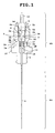
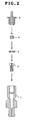
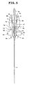
- a pipe electrode holder of the present invention will now be described with reference to Fig. 1 and Fig. 2 .
- a pipe electrode 6 comprises a section 6a having an external diameter of 0.30 - 0.05 mm and a length of 180 mm, and a shank part 6b having an external diameter larger than that of the section 6a and a length of 70 mm.
- the shank part 6b for inserting into a pipe electrode holder has an internal diameter of 1.0 mm so that the pipe electrode is not smashed.
- the pipe electrode holder is comprised of a cylinder 1 , a collet 2 , a washer 3, a seal block 4, and a holder head 5.
- the cylinder 1 has a through hole 1a passing through it.
- a female screw 1b is formed in an upper end of the through hole 1a.
- the internal diameter of the through hole 1a is reduced stepwise from an upper end to a lower end at shoulders 1c and 1d .
- the shoulder 1c has a 45° tapered surface.
- the internal diameter of the through hole 1a further down than the shoulder 1d is slightly larger than the shank part 6b, for example 1.010 mm.
- An annular groove 1e is formed in an outer surface of the cylinder 1, and a flange 1f extending in the radial direction is formed further down than the annular groove 1e.
- a side surface 1g above the annular groove 1e is a tapered surface converging downwards.
- the collet 2 , washer 3 and seal block 4 are sequentially fitted into the through hole 1a from an upper end of the cylinder 1. After that, the holder head 5 capable of adjusting the gripping force of the collet 2 is screwed to the upper end of the cylinder 1 . Assembly of the pipe electrode holder is thus completed.
- the collet 2 is made from a material having good conductivity, such as beryllium alloy, and has a through hole 2a for insertion of the pipe electrode 6 in the center.
- the collet 2 is made up of a slide joint section 2S having four joints 2b formed at equal intervals extending in the radial direction, and a tubular section 2T not containing the joints 2b.
- a 45° tapered surface 2c for engaging with the tapered surface 1c of the cylinder 1 is formed on the slide joint section 2S.
- a 45° tapered surface 2d is also formed on an upper end of the slide joint section 2S.
- the washer 3 has a through hole 3a for insertion of the pipe electrode 6 in its center, and a tapered surface 3b for engaging with the tapered surface 2d of the slide joint section 2S .
- a cylindrical seal block 4 is made of an elastic material such as rubber, and has a through hole 4a for insertion of the pipe electrode 6 in its center.
- a bottom surface of the seal block 4 comes into contact with the top face of the washer 3 .
- a bottom surface of the holder head 5 comes into contact with a top face of the seal block 4.
- the holder head 5 has a through hole 5a for insertion of the pipe electrode 6 in its center.
- a male screw 5b for being screwed into the female screw 1b of the cylinder 1 is formed on a lower end of the holder head 5.
- a protruding section 5c of ⁇ 3 mm extending in the axial direction is formed on the upper end of the holder head 5. Also, a flange 5d having, for example, a hexagonal or rectangular cross section and extending in the radial direction is formed between the male screw 5b and the protruding section 5c.
- the male screw 5b of the holder head 5 is loosened off so that the flange 5d is separated from the top face of the cylinder 1 by a distance of 1 - 2 mm.
- the shank part 6b of the pipe electrode 6 is inserted into the through hole 1a of the cylinder 1 from a lower end of the cylinder 1 .
- a tip end of the shank part 6b of the pipe electrode 6 passes through the through hole 2a of the collet 2 , the through hole 3a of the washer 3 , the through hole 4a of the seal block 4 and the through hole 5a of the holder head 5 , and projects a few mm from the top face of the holder head 5.
- the male screw 5b of the holder head 5 is tightened up until the flange 5d comes into contact with the top face of the cylinder 1 .
- Inclination of the holder head 5 is corrected by the contact of the top face of the cylinder 1 and the flange 5d , and the pipe electrode 6 and the cylinder 1 are arranged coaxially.
- Lowering of the holder head 5 pressurizes the seal block 4 , and the suppression force of the seal block 4 causes the washer 3 and the collet 2 to be moved downwards.
- the tapered surface 3b of the washer 3 slides on the tapered surface 2d of the slide joint section 2S
- the tapered surface 2c of the slide joint section 2S slides on the tapered surface 1c of the cylinder 1 .
- the joints 2b of the collet 2 are closed up so that gripping claws of the collet 2 grip the pipe electrode 6.
- the dimensions of the tapered surface 1c, the collet 2, the washer 3, the seal block 4, the male screw 5b and the flange 5d are designed so that the compressed seal block 4 reliably seals the collet 2 and it is possible for the collet 2 to generate a suitable gripping force. Accordingly, contact between the top face of the cylinder 1 and the flange 5d can always ensure a suitable gripping force. Since the washer 3 is positioned between the seal block 4 and the collet 2 , the compressed seal block 4 is prevented from getting into the joints of the slide joint section 2S .
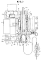
- a hollow spindle 7 of the small hole electric discharge machine is rotatably vertically supported by a bearing 9 .
- the diameter of a through hole 7a of the spindle 7 becomes larger at a lower end side of the spindle 7 so as to accommodate the pipe electrode holder.
- a supply pipe 26 is fitted to an upper end of the spindle 7 using an O-ring 27 in order to supply dielectric fluid to the through hole 7a .
- a timing belt 25 is suspended across a pulley 23b fitted to the spindle 7 and a pulley 23a fitted to an output shaft of a motor 24.
- a beryllium alloy coil spring holder 10 provided with a heat sink fin 10a is fastened to an outer surface of the spindle 7.
- a current feeding brush 22 is pressure welded to the outer surface of the coil spring holder 10.
- a sleeve 11 is provided capable of sliding on the outer surface of the spindle 7.
- a coil spring 12 is held between the coil spring holder 10 and the sleeve 11 , and urges the coil spring 12 downwards.
- a plurality of holes 13 formed in the spindle 7 are arrayed circumferentially at equal intervals around the axis of the spindle 7 .
- a plurality of balls 14 are respectively arranged inside the holes 13.
- a tapered surface 11a of the sleeve 11 presses the balls 14 radially against an inner side.
- a lower end of the sleeve 11 comes into contact with a U-shaped arm 20 , and the arm 20 is attached to one end of a lever 18 by a support bar 19.
- the lever 18 is pivotably supported on a shaft 18a, and an indent 18b is formed in the other end of the lever 18.
- a cylindrical member 17a fitted to a tip end of a piston rod 17 capable of reciprocating inside an air cylinder 16 is fitted into the indent 18b.
- An O-ring case 15 is inserted into the through hole 7a of the spindle 7, and has a hole 15a for accommodating the protruding section 5c of the holder head 5.
- the O-ring 15b is provided to seal up a gap between the O-ring case 15 and the protruding section 5c.
- the arm 20 attached to the lever 18 acts against the spring force of the coil spring 12 to raise the sleeve 11 to an unclamped position.
- the lever 18 , arm 20 and sleeve 11 are as shown by the imaginary line in Fig. 3 .
- the protruding section 5c of the holder head 5 is made to confront the spindle 7, and the pipe electrode holder is fitted into the through hole 7a so as to be arranged coaxial with the spindle 7 .
- the protruding section 5c of the holder head 5 is inserted into the hole 15a.
- the sleeve 11 is released from the arm 20 and is lowered to a clamped position under the spring force of the coil spring 12 .
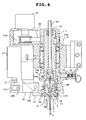
- the pipe electrode holder when the sleeve 11 is in the clamped position is shown in Fig. 4 .
- the balls 14 are pressed radially against an inner side by the tapered surface 11a and engage with an annular groove 1e in the cylinder 1. In this way, the pipe electrode holder is restrained by the balls 14. At this time, the balls 14 are in contact with the tapered surface 1g of the cylinder 1, the tapered surface 11a of the sleeve 11 and a lower surface of the hole 13.
- the pipe electrode holder As the balls 14 are supported at these three contact points, a component of force acting on the balls 14 presses the pipe electrode holder upward. As the flange 1f of the cylinder 1 is pressured to stick fast to the bottom surface of the spindle 7 , the cylinder 1 is reliably arranged coaxially with the spindle 7 .
- current is supplied to the pipe electrode 6 through the brush 22 , the coil spring holder 10 , the spindle 7 , the balls 14 , the cylinder 1 and the collet 2, and dielectric fluid is supplied at a high pressure of 60 - 80 kg/cm 2 from the supply pipe 26 through the through hole 7a of the spindle 7 and the hole 15a of the O-ring case 15 to the inside of the pipe electrode 6. If the sleeve 11 is returned again to the unclamped position, the pipe electrode holder can be lowered down and pulled out.
- the collet 2 in Fig. 5 similarly to the collet 2 in Fig. 1 , comprises a slide joint section 2S having four joints 2b formed at equal intervals extending in the radial direction, and a tube section 2T.
- a 45° tapered surface 2e formed on a lower end of the slide joint section 2S is engaged with a tapered surface 1h converging downwards formed in the through hole 1a .
- a bottom surface of the seal block 4 is in contact with a top face of the tube section 2T not containing the joints 2b, which means that the washer 3 in Fig. 1 is not necessary.
- the gripping force of the collet 2 is adjusted by the holder head 5.
- the seal block 4 is compressed by tightening the male screw 5b of the holder head 5, and the elastic force of the seal block 4 causes the collet 2 to move downwards. As a result, the tapered surface 2e of the collet 2 slides on the tapered surface 1h of the cylinder 1. The joints 2b of the collet 2 are then closed so as to grip the pipe electrode 6 with the gripping claws of the collet 2 .
- the present invention is not intended to be limited to the form disclosed. Various improvements and variations are clearly possible upon reference to the above description. For example, it is possible to form at least one joint 2b in the collet 2 , and it is possible to use a suitable well known collet 2 for gripping an elongated electrode.
- the illustrated embodiments have been selected simply to describe the essence and practical application of the invention. The scope of the invention is defined in the attached claims.
Landscapes
- Engineering & Computer Science (AREA)
- Mechanical Engineering (AREA)
- Chemical & Material Sciences (AREA)
- Chemical Kinetics & Catalysis (AREA)
- Electrochemistry (AREA)
- Physics & Mathematics (AREA)
- Thermal Sciences (AREA)
- Electrical Discharge Machining, Electrochemical Machining, And Combined Machining (AREA)
Claims (6)
- Porte-électrode tubulaire, pour maintenir une électrode tubulaire (6), capable d'être attaché coaxialement à une broche rotative (7) d'une machine de formation de petits trous à décharge électrique, comprenant :un cylindre (1) capable d'être monté dans une broche rotative (7), ayant une extrémité supérieure filetée et un trou traversant (1a) ;une bague de serrage (2) ayant un trou (2a) à travers lequel passe l'électrode tubulaire (6), pour serrer une électrode tubulaire montée dans le trou traversant du cylindre ;et une tête de porte-électrode (5) à visser dans l'extrémité supérieure filetée du cylindre afin de rendre réglable la force de serrage de la bague de serrage.
- Porte-électrode tubulaire selon la revendication 1, le porte-électrode tubulaire comprenant en outre un bloc d'étanchéité élastique (4) ayant un trou traversant (4a) à travers lequel l'électrode tubulaire passe, monté dans le trou traversant du cylindre entre la bague de serrage et la tête du porte-électrode.
- Porte-électrode tubulaire selon la revendication 2, ce porte-électrode tubulaire comprenant en outre une rondelle (3), ayant un trou traversant (3a) à travers lequel passe l'électrode tubulaire, montée dans le trou traversant du cylindre entre la bague de serrage et le bloc d'étanchéité, la bague de serrage ayant une première surface conique (2d) avec un joint, et la rondelle ayant une surface conique (3d) pour s'engager avec la première surface conique.
- Porte-électrode tubulaire selon la revendication 2, la bague de serrage ayant aussi une deuxième surface conique (2c, 2e) avec un joint, et une surface conique (1c, 1h) pour s'engager avec la deuxième surface conique étant formée dans le trou traversant du cylindre.
- Porte-électrode tubulaire selon la revendication 2, une bride (1f) s'étendant radialement et capable de contenir une surface inférieure de la broche rotative étant formée dans le cylindre.
- Porte-électrode tubulaire selon la revendication 2, une bride (5d) s'étendant radialement et capable d'entrer en contact avec une face supérieure du cylindre étant formée sur la tête du porte-électrode.
Applications Claiming Priority (3)
| Application Number | Priority Date | Filing Date | Title |
|---|---|---|---|
| JP11315199A JP3406860B2 (ja) | 1999-04-21 | 1999-04-21 | 放電加工用パイプ電極ホルダ |
| JP11315199 | 1999-04-21 | ||
| PCT/JP2000/002649 WO2000064617A1 (fr) | 1999-04-21 | 2000-04-21 | Porte-electrode tubulaire |
Publications (3)
| Publication Number | Publication Date |
|---|---|
| EP1138428A1 EP1138428A1 (fr) | 2001-10-04 |
| EP1138428A4 EP1138428A4 (fr) | 2005-07-06 |
| EP1138428B1 true EP1138428B1 (fr) | 2008-04-02 |
Family
ID=14604872
Family Applications (1)
| Application Number | Title | Priority Date | Filing Date |
|---|---|---|---|
| EP00917426A Expired - Lifetime EP1138428B1 (fr) | 1999-04-21 | 2000-04-21 | Porte-electrode tubulaire |
Country Status (5)
| Country | Link |
|---|---|
| US (1) | US6448528B1 (fr) |
| EP (1) | EP1138428B1 (fr) |
| JP (1) | JP3406860B2 (fr) |
| DE (1) | DE60038482T2 (fr) |
| WO (1) | WO2000064617A1 (fr) |
Families Citing this family (24)
| Publication number | Priority date | Publication date | Assignee | Title |
|---|---|---|---|---|
| CN100509234C (zh) | 2004-01-23 | 2009-07-08 | 三菱电机株式会社 | 电火花加工设备 |
| CN100411795C (zh) * | 2004-05-13 | 2008-08-20 | 嘉昇机电工业股份有限公司 | 细孔放电加工机自动更换电极装置 |
| US8664559B2 (en) | 2005-02-28 | 2014-03-04 | Mitsubishi Denki Kabushiki Kaisha | Electrical discharge machine |
| TWI259116B (en) * | 2005-06-24 | 2006-08-01 | Tai I Electron Machining Co Lt | Method and device for EDM drill machine for use in clamping and positioning tube electrodes |
| CN100556600C (zh) * | 2005-07-07 | 2009-11-04 | 台一电子机械股份有限公司 | 细孔放电加工电极管夹持时的定位方法及装置 |
| US20070151954A1 (en) * | 2006-01-05 | 2007-07-05 | General Electric Company | Methods and apparatus for fabricating components |
| CN100556601C (zh) * | 2006-07-28 | 2009-11-04 | 台一电子机械股份有限公司 | 细孔放电加工机夹持电极管的方法及装置 |
| US9145313B2 (en) | 2009-07-02 | 2015-09-29 | Avivid Water Technology, Llc | Turboelectric coagulation apparatus |
| US8500989B2 (en) * | 2009-07-02 | 2013-08-06 | Avivid Water Technology, Llc | Turboelectric coagulation apparatus |
| CN102218575B (zh) * | 2011-05-23 | 2016-12-21 | 广东工业大学 | 一种微细电解及微细电火花加工机床的主轴系统 |
| US9050671B2 (en) * | 2011-09-28 | 2015-06-09 | Turbine Engine Components Technologies Corporation | Electrode holder for EDM coupled to a milling machine |
| CN103071872B (zh) * | 2013-01-24 | 2015-02-11 | 苏州群伦精密机电工业有限公司 | 一种放电加工机的旋转轴装置 |
| CN103252547B (zh) * | 2013-05-17 | 2015-07-15 | 哈尔滨汽轮机厂有限责任公司 | 一种电火花加工用内冲液式电极刷 |
| KR101434353B1 (ko) | 2014-03-19 | 2014-08-29 | (주)케이.티.씨 | 미세 전극 척킹장치 |
| JP6465972B2 (ja) * | 2015-06-12 | 2019-02-06 | 株式会社牧野フライス製作所 | 細穴放電加工機 |
| CN109014455B (zh) | 2018-06-22 | 2020-03-06 | 株式会社沙迪克 | 放电加工装置 |
| CN110560805B (zh) * | 2019-08-06 | 2020-11-20 | 沙迪克(厦门)有限公司 | 放电加工装置的放电加工单元 |
| CN110560802B (zh) * | 2019-10-09 | 2024-06-14 | 大连理工大学 | 一种用于大深径比微孔高速电火花加工的装置 |
| CN110899879B (zh) * | 2019-10-30 | 2021-01-01 | 沙迪克(厦门)有限公司 | 放电加工装置的下侧引导单元 |
| EP4067471A4 (fr) * | 2019-11-26 | 2024-06-26 | Yokogawa Electric Corporation | Dispositif de pointe, ensemble contenant de pointe, dispositif d'électrode de pointe et ensemble d'électrodes de pointe |
| US12583771B2 (en) | 2020-07-08 | 2026-03-24 | Avivid Water Technology, Llc | Turboelectric coagulation apparatus including cassette-style anode assembly |
| CN113042833B (zh) * | 2021-03-30 | 2022-02-11 | 合肥工业大学 | 一种薄壁圆筒群孔加工装置及其加工方法 |
| CN115476007A (zh) * | 2022-09-20 | 2022-12-16 | 苏州亚马森机床有限公司 | 气动旋转头 |
| CN116021281B (zh) * | 2023-02-24 | 2025-11-21 | 东台润田精密科技有限公司 | 光伏板端连接器自动组装设备 |
Family Cites Families (12)
| Publication number | Priority date | Publication date | Assignee | Title |
|---|---|---|---|---|
| US4538043A (en) * | 1983-05-23 | 1985-08-27 | Alexander Rayburn G | Water shield for a metal disintegrator device |
| JPS6411735A (en) * | 1987-07-03 | 1989-01-17 | Mitsubishi Electric Corp | Electric discharge machine |
| JPH01205922A (ja) * | 1988-02-08 | 1989-08-18 | Fanuc Ltd | イニシャルホール加工装置 |
| JP2800119B2 (ja) * | 1988-03-24 | 1998-09-21 | 西部電機株式会社 | 電極交換装置付き放電加工機 |
| US5420388A (en) * | 1989-03-29 | 1995-05-30 | Charmilles Technologies | Tool-holder and rapid rotary spindle |
| JP2755439B2 (ja) * | 1989-07-27 | 1998-05-20 | 株式会社放電精密加工研究所 | 放電細穴加工機のシール装置 |
| JPH0441129A (ja) * | 1990-06-01 | 1992-02-12 | Mitsubishi Electric Corp | ワイヤ放電加工機 |
| JP3180870B2 (ja) * | 1994-10-25 | 2001-06-25 | 株式会社日研工作所 | 工具ホルダ |
| JP3050773B2 (ja) * | 1995-04-18 | 2000-06-12 | 株式会社エレニックス | 細穴放電加工機に対する電極、電極ガイド交換方法及び同方法に使用する交換装置、電極ホルダ、細穴放電加工機 |
| DE29715782U1 (de) * | 1997-09-03 | 1997-12-11 | Abacus Automatisierungstechnik GmbH, 49080 Osnabrück | Elektrodenwechsler für Funkenerosionsmaschinen, insbesondere funkenerosive Bohrmaschinen |
| US5977503A (en) * | 1997-11-03 | 1999-11-02 | Leach Thomas S. | Attachment device for electrical discharge machine |
| JP2000094219A (ja) * | 1998-09-28 | 2000-04-04 | Sodick Co Ltd | 放電加工用極細パイプ電極及び電極装置 |
-
1999
- 1999-04-21 JP JP11315199A patent/JP3406860B2/ja not_active Expired - Fee Related
-
2000
- 2000-04-21 DE DE60038482T patent/DE60038482T2/de not_active Expired - Lifetime
- 2000-04-21 US US09/720,093 patent/US6448528B1/en not_active Expired - Lifetime
- 2000-04-21 WO PCT/JP2000/002649 patent/WO2000064617A1/fr not_active Ceased
- 2000-04-21 EP EP00917426A patent/EP1138428B1/fr not_active Expired - Lifetime
Also Published As
| Publication number | Publication date |
|---|---|
| JP2000301417A (ja) | 2000-10-31 |
| EP1138428A4 (fr) | 2005-07-06 |
| EP1138428A1 (fr) | 2001-10-04 |
| US6448528B1 (en) | 2002-09-10 |
| DE60038482T2 (de) | 2009-04-09 |
| WO2000064617A1 (fr) | 2000-11-02 |
| DE60038482D1 (de) | 2008-05-15 |
| JP3406860B2 (ja) | 2003-05-19 |
Similar Documents
| Publication | Publication Date | Title |
|---|---|---|
| US6448528B1 (en) | Tubular electrode holder | |
| US2385665A (en) | Electrical device | |
| KR20140039214A (ko) | 홀더 장치 | |
| CN1494975A (zh) | 具有可替换的焊头的焊接加热器筒及利用该焊接加热器筒的烙铁 | |
| US2490302A (en) | Means for removing embedded material | |
| KR900017046A (ko) | 증기발생기 튜브로부터의 폐쇄 플러그 추출 방법 및 장치 | |
| US4138909A (en) | Bolt extractor | |
| US5561336A (en) | Device for supplying electric current to a rotating part and its application in EDM | |
| US4777342A (en) | Plasma cutting torch with improved electrode holders | |
| CN218891283U (zh) | 电极治具 | |
| US6037558A (en) | Integrated low inertia projection welding head and cylinder | |
| KR101871664B1 (ko) | 일체형 용접용 토치 | |
| EP0156152A2 (fr) | Guide d'électrode à étanchéité intrinsèque | |
| US2718581A (en) | Mechanism for disintegrating metals by an electric arc | |
| JP6033203B2 (ja) | 電極棒使用の熱加工トーチ | |
| US2606988A (en) | Arc welding electrode holder | |
| US5003146A (en) | Universal fitting for metal disintegration electrodes | |
| US2829240A (en) | Holders for welding electrodes | |
| US4461948A (en) | Collet system for arc welding torches | |
| US7053329B2 (en) | System and method for securing a welding electrode to a welding torch | |
| KR100258846B1 (ko) | 공작기계용 작업물 송급장치 | |
| GB2247204A (en) | Flaw of dielectric fluid in electrical discharge machining | |
| CN214867933U (zh) | 一种焊枪清理头及便捷式焊枪清理装置 | |
| SU1632687A1 (ru) | Электрододержатель дл ручной дуговой сварки | |
| CN219042016U (zh) | 一种用于旋转工件加热的装置 |
Legal Events
| Date | Code | Title | Description |
|---|---|---|---|
| PUAI | Public reference made under article 153(3) epc to a published international application that has entered the european phase |
Free format text: ORIGINAL CODE: 0009012 |
|
| 17P | Request for examination filed |
Effective date: 20001117 |
|
| AK | Designated contracting states |
Kind code of ref document: A1 Designated state(s): AT BE CH CY DE DK ES FI FR GB GR IE IT LI LU MC NL PT SE |
|
| RBV | Designated contracting states (corrected) |
Designated state(s): DE GB |
|
| A4 | Supplementary search report drawn up and despatched |
Effective date: 20050524 |
|
| GRAP | Despatch of communication of intention to grant a patent |
Free format text: ORIGINAL CODE: EPIDOSNIGR1 |
|
| GRAS | Grant fee paid |
Free format text: ORIGINAL CODE: EPIDOSNIGR3 |
|
| GRAA | (expected) grant |
Free format text: ORIGINAL CODE: 0009210 |
|
| AK | Designated contracting states |
Kind code of ref document: B1 Designated state(s): DE GB |
|
| REG | Reference to a national code |
Ref country code: GB Ref legal event code: FG4D |
|
| REF | Corresponds to: |
Ref document number: 60038482 Country of ref document: DE Date of ref document: 20080515 Kind code of ref document: P |
|
| PLBE | No opposition filed within time limit |
Free format text: ORIGINAL CODE: 0009261 |
|
| STAA | Information on the status of an ep patent application or granted ep patent |
Free format text: STATUS: NO OPPOSITION FILED WITHIN TIME LIMIT |
|
| 26N | No opposition filed |
Effective date: 20090106 |
|
| PGFP | Annual fee paid to national office [announced via postgrant information from national office to epo] |
Ref country code: DE Payment date: 20180420 Year of fee payment: 19 |
|
| PGFP | Annual fee paid to national office [announced via postgrant information from national office to epo] |
Ref country code: GB Payment date: 20180418 Year of fee payment: 19 |
|
| REG | Reference to a national code |
Ref country code: DE Ref legal event code: R119 Ref document number: 60038482 Country of ref document: DE |
|
| GBPC | Gb: european patent ceased through non-payment of renewal fee |
Effective date: 20190421 |
|
| PG25 | Lapsed in a contracting state [announced via postgrant information from national office to epo] |
Ref country code: DE Free format text: LAPSE BECAUSE OF NON-PAYMENT OF DUE FEES Effective date: 20191101 Ref country code: GB Free format text: LAPSE BECAUSE OF NON-PAYMENT OF DUE FEES Effective date: 20190421 |