EP1138435A2 - Machine-outil avec codeur tournant - Google Patents
Machine-outil avec codeur tournant Download PDFInfo
- Publication number
- EP1138435A2 EP1138435A2 EP01105181A EP01105181A EP1138435A2 EP 1138435 A2 EP1138435 A2 EP 1138435A2 EP 01105181 A EP01105181 A EP 01105181A EP 01105181 A EP01105181 A EP 01105181A EP 1138435 A2 EP1138435 A2 EP 1138435A2
- Authority
- EP
- European Patent Office
- Prior art keywords
- machine tool
- spindle
- magnetic field
- bearing
- field sensor
- Prior art date
- Legal status (The legal status is an assumption and is not a legal conclusion. Google has not performed a legal analysis and makes no representation as to the accuracy of the status listed.)
- Withdrawn
Links
Images
Classifications
-
- B—PERFORMING OPERATIONS; TRANSPORTING
- B23—MACHINE TOOLS; METAL-WORKING NOT OTHERWISE PROVIDED FOR
- B23Q—DETAILS, COMPONENTS, OR ACCESSORIES FOR MACHINE TOOLS, e.g. ARRANGEMENTS FOR COPYING OR CONTROLLING; MACHINE TOOLS IN GENERAL CHARACTERISED BY THE CONSTRUCTION OF PARTICULAR DETAILS OR COMPONENTS; COMBINATIONS OR ASSOCIATIONS OF METAL-WORKING MACHINES, NOT DIRECTED TO A PARTICULAR RESULT
- B23Q17/00—Arrangements for observing, indicating or measuring on machine tools
- B23Q17/22—Arrangements for observing, indicating or measuring on machine tools for indicating or measuring existing or desired position of tool or work
-
- B—PERFORMING OPERATIONS; TRANSPORTING
- B23—MACHINE TOOLS; METAL-WORKING NOT OTHERWISE PROVIDED FOR
- B23Q—DETAILS, COMPONENTS, OR ACCESSORIES FOR MACHINE TOOLS, e.g. ARRANGEMENTS FOR COPYING OR CONTROLLING; MACHINE TOOLS IN GENERAL CHARACTERISED BY THE CONSTRUCTION OF PARTICULAR DETAILS OR COMPONENTS; COMBINATIONS OR ASSOCIATIONS OF METAL-WORKING MACHINES, NOT DIRECTED TO A PARTICULAR RESULT
- B23Q11/00—Accessories fitted to machine tools for keeping tools or parts of the machine in good working condition or for cooling work; Safety devices specially combined with or arranged in, or specially adapted for use in connection with, machine tools
- B23Q11/08—Protective coverings for parts of machine tools; Splash guards
-
- B—PERFORMING OPERATIONS; TRANSPORTING
- B23—MACHINE TOOLS; METAL-WORKING NOT OTHERWISE PROVIDED FOR
- B23Q—DETAILS, COMPONENTS, OR ACCESSORIES FOR MACHINE TOOLS, e.g. ARRANGEMENTS FOR COPYING OR CONTROLLING; MACHINE TOOLS IN GENERAL CHARACTERISED BY THE CONSTRUCTION OF PARTICULAR DETAILS OR COMPONENTS; COMBINATIONS OR ASSOCIATIONS OF METAL-WORKING MACHINES, NOT DIRECTED TO A PARTICULAR RESULT
- B23Q17/00—Arrangements for observing, indicating or measuring on machine tools
- B23Q17/10—Arrangements for observing, indicating or measuring on machine tools for indicating or measuring cutting speed or number of revolutions
-
- G—PHYSICS
- G01—MEASURING; TESTING
- G01D—MEASURING NOT SPECIALLY ADAPTED FOR A SPECIFIC VARIABLE; ARRANGEMENTS FOR MEASURING TWO OR MORE VARIABLES NOT COVERED IN A SINGLE OTHER SUBCLASS; TARIFF METERING APPARATUS; MEASURING OR TESTING NOT OTHERWISE PROVIDED FOR
- G01D5/00—Mechanical means for transferring the output of a sensing member; Means for converting the output of a sensing member to another variable where the form or nature of the sensing member does not constrain the means for converting; Transducers not specially adapted for a specific variable
- G01D5/26—Mechanical means for transferring the output of a sensing member; Means for converting the output of a sensing member to another variable where the form or nature of the sensing member does not constrain the means for converting; Transducers not specially adapted for a specific variable characterised by optical transfer means, i.e. using infrared, visible, or ultraviolet light
- G01D5/32—Mechanical means for transferring the output of a sensing member; Means for converting the output of a sensing member to another variable where the form or nature of the sensing member does not constrain the means for converting; Transducers not specially adapted for a specific variable characterised by optical transfer means, i.e. using infrared, visible, or ultraviolet light with attenuation or whole or partial obturation of beams of light
- G01D5/34—Mechanical means for transferring the output of a sensing member; Means for converting the output of a sensing member to another variable where the form or nature of the sensing member does not constrain the means for converting; Transducers not specially adapted for a specific variable characterised by optical transfer means, i.e. using infrared, visible, or ultraviolet light with attenuation or whole or partial obturation of beams of light the beams of light being detected by photocells
- G01D5/347—Mechanical means for transferring the output of a sensing member; Means for converting the output of a sensing member to another variable where the form or nature of the sensing member does not constrain the means for converting; Transducers not specially adapted for a specific variable characterised by optical transfer means, i.e. using infrared, visible, or ultraviolet light with attenuation or whole or partial obturation of beams of light the beams of light being detected by photocells using displacement encoding scales
- G01D5/3473—Circular or rotary encoders
- G01D5/34738—Axles; Driving or coupling means
Definitions
- the invention relates to a machine tool with a machine bed and at least one spindle or shaft in a bed-fixed bearing arrangement is rotatably mounted and coupled to an encoder system.
- measuring systems which are highly precise in the speed or angle of rotation of a spindle or shaft can measure, are also very sensitive to environmental influences.
- parts of the machine tool there are the parts of the machine tool, their position or movement to be detected, exposed to high mechanical loads, which uncontrolled and unwanted deflections and vibrations can.
- the signals from the measuring systems are also through Pollution particles such as finest chips affected in each cutting machine tool are available.
- the invention has for its object a machine tool Specify above type in which the encoder system is optimal is protected against external influences in order to achieve highly precise measurement results receive.
- the solution according to the invention has two major advantages.
- it is Bearing arrangement of a spindle or shaft on a machine tool basically hermetically sealed, otherwise the individual bearings will go through Coolant, finest metal shavings or other dirt particles in would be ruined in no time.
- This hermetic seal of the bearing assembly guarantees optimal protection of the encoder system against Pollution.
- the other is the influence of radial forces on the spindle or shaft within the bearing arrangement least so that here also under maximum load disturbances of the measurement results due to radial forces can be largely excluded.
- a per se is particularly suitable for installation in the bearing arrangement
- Known encoder system which is rotatably coupled to the spindle Measuring gear and a magnetic field sensor associated therewith.
- the measuring gear is connected to a spacer sleeve is clamped between roller bearing rings of the bearing assembly.
- the measuring gear be integrally formed with the spacer sleeve, whereby Tolerances in the assembly of the measuring gear relative to the spindle are reduced can be and thereby the accuracy of the encoder system is increased.
- the magnetic field sensor itself is preferably in a recess in the Warehouse arranged and appropriately so that it is radial is adjustable with respect to the spindle axis.
- the recess is through a Cover hermetically sealed.
- the magnetic field sensor remains for Adjustment or maintenance work easily accessible.
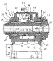
- the bearing arrangement shown generally designated 10 in the figure has a bearing housing 12 which at its lower end with one not closer shown machine bed 14 is connected and a continuous cylindrical Bearing bore 16 has.
- a hollow spindle is in the cylindrical bearing bore 16 18 stored with the help of roller bearings 20, which are in pairs near the end of the Bearing bore 16 arranged and are designed so that the spindle 18 in can absorb axial forces in both axial directions.
- the one on the right in the figure outer bearing 20 lies with its inner ring 22 on a collar 24 of the spindle and with its outer bearing ring 26 on an annular flange 28, which is made of the bearing bore 16 protruding end of the spindle 18 and the Bearing bore 16 closes tightly.
- the inner bearing rings 22 of the roller bearings 20 and the inner spacer sleeve 30 are by one on the Spindle 18 seated clamping ring 34 axially clamped.
- the outer bearing rings 26 the roller bearing 20 and the outer spacer sleeve 32 are in the same way an annular flange 36 clamped on the left end of the figure in the figure Bearing housing 12 is screwed on.
- the clamping ring 34 and the ring flange 36 interlock so that they form a labyrinth seal 38. So far described bearing arrangement is known per se.
- a measuring gear 40 is formed in one piece with the inner spacer sleeve 30, which consists of a soft magnetic steel and in a known manner is the yardstick of a magnetic gear encoder that is highly precise Measurement of the angle of rotation or the speed of the spindle enables.
- the Measuring gear 40 is associated with a magnetic field sensor 42, which is in a recess or pocket 44 is arranged in the bearing housing 12. The order is made by means of a sliding guide 46 such that the magnetic field sensor 42 is radial with respect to the spindle axis at a predetermined distance from the Scope of the measuring gear 40 can be adjusted.
- the recess 44 can be hermetically sealed by a cover 48. Through the cover 48 are the supply and signal lines 50 for the magnetic field sensor 42 passed and connected to a terminal head 52 through which the Magnetic field sensor 42 can be connected to an evaluation and display unit can.
- Magnetic field sensor 42 magnetic field sensitive resistors.
- One in the Magnetic field sensor 42 containing magnet generates a magnetic field that the magnetic field-sensitive resistors.
- the magnetic flux through the Magnetic field sensitive resistors change depending on the Resistance of passing measuring gear periodically depending on whether a Tooth or a tooth gap the magnetic field sensitive resistors opposite.
- the measuring system is known as such and therefore does not need to be explained in more detail.
- the measuring gear 40 is axial lies at a point where it is formed in one piece with the spacer sleeve 30, ensures an optimal concentricity which is very important for the measuring process. Out for this reason there are differences in distance during a spindle revolution extremely low between the magnetic field sensor and the measuring gear. This in turn enables a powerful and exact measurement signal. It is also located the encoder system or measuring system 40, 42 in a room that is also under the harsh working conditions of a machine tool free of Impurities can be kept, especially free of metal chips could interfere with the magnetic measuring system.
Landscapes
- Engineering & Computer Science (AREA)
- Mechanical Engineering (AREA)
- Physics & Mathematics (AREA)
- General Physics & Mathematics (AREA)
- Machine Tool Sensing Apparatuses (AREA)
Applications Claiming Priority (2)
| Application Number | Priority Date | Filing Date | Title |
|---|---|---|---|
| DE2000115419 DE10015419A1 (de) | 2000-03-28 | 2000-03-28 | Werkzeugmaschine mit Drehgebersystem |
| DE10015419 | 2000-03-28 |
Publications (2)
| Publication Number | Publication Date |
|---|---|
| EP1138435A2 true EP1138435A2 (fr) | 2001-10-04 |
| EP1138435A3 EP1138435A3 (fr) | 2002-07-03 |
Family
ID=7636719
Family Applications (1)
| Application Number | Title | Priority Date | Filing Date |
|---|---|---|---|
| EP01105181A Withdrawn EP1138435A3 (fr) | 2000-03-28 | 2001-03-02 | Machine-outil avec codeur tournant |
Country Status (2)
| Country | Link |
|---|---|
| EP (1) | EP1138435A3 (fr) |
| DE (1) | DE10015419A1 (fr) |
Cited By (2)
| Publication number | Priority date | Publication date | Assignee | Title |
|---|---|---|---|---|
| WO2006010900A1 (fr) * | 2004-07-28 | 2006-02-02 | Gsi Group Limited | Capteurs de vitesse de broche d'usinage |
| EP2269768A3 (fr) * | 2009-06-29 | 2011-04-13 | Maschinenfabrik Berthold Hermle AG | Broche d'outils pour une machine combinée de fraisage/tournage dotée d'un outil fixe ou rotatif |
Family Cites Families (2)
| Publication number | Priority date | Publication date | Assignee | Title |
|---|---|---|---|---|
| DE3765236D1 (de) * | 1986-12-22 | 1990-10-31 | Siemens Ag | Winkellagegeber mit fotoelektrisch abtastbarer geberscheibe und zweifach gelagerter geberwelle. |
| JP2720681B2 (ja) * | 1992-01-06 | 1998-03-04 | 株式会社村田製作所 | 移動体の移動検出装置 |
-
2000
- 2000-03-28 DE DE2000115419 patent/DE10015419A1/de not_active Withdrawn
-
2001
- 2001-03-02 EP EP01105181A patent/EP1138435A3/fr not_active Withdrawn
Cited By (3)
| Publication number | Priority date | Publication date | Assignee | Title |
|---|---|---|---|---|
| WO2006010900A1 (fr) * | 2004-07-28 | 2006-02-02 | Gsi Group Limited | Capteurs de vitesse de broche d'usinage |
| EP1935561A1 (fr) * | 2004-07-28 | 2008-06-25 | GSI Group Limited | Usinage de sondes à vitesse axiale |
| EP2269768A3 (fr) * | 2009-06-29 | 2011-04-13 | Maschinenfabrik Berthold Hermle AG | Broche d'outils pour une machine combinée de fraisage/tournage dotée d'un outil fixe ou rotatif |
Also Published As
| Publication number | Publication date |
|---|---|
| DE10015419A1 (de) | 2001-10-04 |
| EP1138435A3 (fr) | 2002-07-03 |
Similar Documents
| Publication | Publication Date | Title |
|---|---|---|
| DE4219318C2 (de) | Verfahren und Vorrichtung zum Bestimmen des Kontaktwinkels von Kugellagern | |
| DE102007050111B4 (de) | Verfahren und Anlage-Sensorvorrichtung zu einer Anlagemessung bei einer Werkzeugmaschine | |
| DE4243623A1 (en) | Revolution rate detector, esp. for vehicle bearings - contains pulse transducer ring, press seated ring with sensor element in aperture, and housing filled with setting resin for shock resistance | |
| DE4030229C2 (de) | Berührungsloser Winkelgeber | |
| EP0272544A1 (fr) | Détecteur de position angulaire à disque tournant palpable par voie photoélectrique et axe de rotation à double roulement | |
| WO2021069014A1 (fr) | Appareil de détection de position d'angle de rotation d'un arbre rotatif et agencement de direction d'un véhicule | |
| EP0711618A1 (fr) | Procédé d'usinage d'un essieu et équipement pour la mise en oeuvre du procédé | |
| EP4051918B1 (fr) | Banc d'essai | |
| DE19640895B4 (de) | Wälzlager mit einer integrierten Drehzahlmeßeinrichtung | |
| DE1402955A1 (de) | Unterflur-Profildrehmaschine fuer die Bearbeitung der Umrisse nicht ausgebundener Radsaetze | |
| DE102014203517A1 (de) | Wälzlager mit einer integrierten Winkelmesseinrichtung | |
| DE10329293A1 (de) | Einrichtung zur Erfassung einer Drehbewegung in einer Fahrzeug-Lenkeinrichtung | |
| DE3905251C2 (de) | Vorrichtung zum Ermitteln des in einer Welle übertragenen Drehmoments | |
| DE102015219167A1 (de) | Wälzlageranordnung | |
| EP1293027B1 (fr) | Moteur electrique et arbre de commande a moteur electrique integre | |
| EP1138435A2 (fr) | Machine-outil avec codeur tournant | |
| DE29512250U1 (de) | Vorrichtung zur Überprüfung der Genauigkeit einer Kreisbahn einer Arbeitsspindel | |
| DE9305385U1 (de) | Anordnung zur berührungsfreien Erfassung der Drehzahl oder Position eines drehbaren Geberteils | |
| DE921718C (de) | Fuehlhebelmessgeraet | |
| DE4103561C2 (de) | Drehstellungsgeber für die Erfassung einer Rotorposition | |
| EP1064120A1 (fr) | Procede pour l'usinage de surfaces planes d'un frein a disque pour des vehicules automobiles | |
| DE102009056355A1 (de) | Wälzlager mit einer Maßverkörperung | |
| DE3922860A1 (de) | Messeinrichtung zur bestimmung des drehmoments | |
| DE4415620C2 (de) | Falzklappenzylinder | |
| DE102017205947A1 (de) | Drehzahlsensorvorrichtung für ein Fahrzeug, Fahrzeug |
Legal Events
| Date | Code | Title | Description |
|---|---|---|---|
| PUAI | Public reference made under article 153(3) epc to a published international application that has entered the european phase |
Free format text: ORIGINAL CODE: 0009012 |
|
| AK | Designated contracting states |
Kind code of ref document: A2 Designated state(s): AT BE CH CY DE DK ES FI FR GB GR IE IT LI LU MC NL PT SE TR |
|
| AX | Request for extension of the european patent |
Free format text: AL;LT;LV;MK;RO;SI |
|
| PUAL | Search report despatched |
Free format text: ORIGINAL CODE: 0009013 |
|
| AK | Designated contracting states |
Kind code of ref document: A3 Designated state(s): AT BE CH CY DE DK ES FI FR GB GR IE IT LI LU MC NL PT SE TR |
|
| AX | Request for extension of the european patent |
Free format text: AL;LT;LV;MK;RO;SI |
|
| RIC1 | Information provided on ipc code assigned before grant |
Free format text: 7B 23Q 17/00 A, 7G 01B 21/22 B, 7B 23Q 17/10 B, 7B 23Q 1/70 B |
|
| 17P | Request for examination filed |
Effective date: 20020829 |
|
| 17Q | First examination report despatched |
Effective date: 20021129 |
|
| AKX | Designation fees paid |
Designated state(s): AT BE CH CY DE DK ES FI FR GB GR IE IT LI LU MC NL PT SE TR |
|
| STAA | Information on the status of an ep patent application or granted ep patent |
Free format text: STATUS: THE APPLICATION IS DEEMED TO BE WITHDRAWN |
|
| 18D | Application deemed to be withdrawn |
Effective date: 20030331 |