EP1138900A2 - Moteur à combustion à injection directe et procédé de commande de combustion au démarrage - Google Patents
Moteur à combustion à injection directe et procédé de commande de combustion au démarrage Download PDFInfo
- Publication number
- EP1138900A2 EP1138900A2 EP01106467A EP01106467A EP1138900A2 EP 1138900 A2 EP1138900 A2 EP 1138900A2 EP 01106467 A EP01106467 A EP 01106467A EP 01106467 A EP01106467 A EP 01106467A EP 1138900 A2 EP1138900 A2 EP 1138900A2
- Authority
- EP
- European Patent Office
- Prior art keywords
- fuel
- catalyst
- cylinder
- type internal
- internal combustion
- Prior art date
- Legal status (The legal status is an assumption and is not a legal conclusion. Google has not performed a legal analysis and makes no representation as to the accuracy of the status listed.)
- Withdrawn
Links
- 238000002485 combustion reaction Methods 0.000 title claims abstract description 168
- 238000002347 injection Methods 0.000 title claims abstract description 125
- 239000007924 injection Substances 0.000 title claims abstract description 125
- 238000000034 method Methods 0.000 title claims description 43
- 239000000446 fuel Substances 0.000 claims abstract description 152
- 239000003054 catalyst Substances 0.000 claims abstract description 103
- 230000003213 activating effect Effects 0.000 claims abstract description 17
- 238000004140 cleaning Methods 0.000 claims abstract 3
- 239000007789 gas Substances 0.000 claims description 37
- 230000006835 compression Effects 0.000 claims description 20
- 238000007906 compression Methods 0.000 claims description 20
- QVGXLLKOCUKJST-UHFFFAOYSA-N atomic oxygen Chemical compound [O] QVGXLLKOCUKJST-UHFFFAOYSA-N 0.000 claims description 19
- 229910052760 oxygen Inorganic materials 0.000 claims description 19
- 239000001301 oxygen Substances 0.000 claims description 19
- 239000007921 spray Substances 0.000 claims description 15
- XLYOFNOQVPJJNP-UHFFFAOYSA-N water Substances O XLYOFNOQVPJJNP-UHFFFAOYSA-N 0.000 claims description 12
- 230000004913 activation Effects 0.000 claims description 3
- 239000000203 mixture Substances 0.000 claims description 3
- 239000000498 cooling water Substances 0.000 claims description 2
- 239000000779 smoke Substances 0.000 description 12
- 230000000630 rising effect Effects 0.000 description 5
- 230000009467 reduction Effects 0.000 description 4
- 238000011144 upstream manufacturing Methods 0.000 description 4
- 238000010586 diagram Methods 0.000 description 3
- 238000013459 approach Methods 0.000 description 2
- 238000006243 chemical reaction Methods 0.000 description 2
- 230000006872 improvement Effects 0.000 description 2
- 230000007246 mechanism Effects 0.000 description 2
- 230000004044 response Effects 0.000 description 2
- 230000008901 benefit Effects 0.000 description 1
- 238000007796 conventional method Methods 0.000 description 1
- 230000003111 delayed effect Effects 0.000 description 1
- 238000009792 diffusion process Methods 0.000 description 1
- 230000000694 effects Effects 0.000 description 1
- 230000002708 enhancing effect Effects 0.000 description 1
- 239000007788 liquid Substances 0.000 description 1
- 230000003647 oxidation Effects 0.000 description 1
- 238000007254 oxidation reaction Methods 0.000 description 1
- 230000035515 penetration Effects 0.000 description 1
- 238000010792 warming Methods 0.000 description 1
Images





Classifications
-
- F—MECHANICAL ENGINEERING; LIGHTING; HEATING; WEAPONS; BLASTING
- F02—COMBUSTION ENGINES; HOT-GAS OR COMBUSTION-PRODUCT ENGINE PLANTS
- F02D—CONTROLLING COMBUSTION ENGINES
- F02D41/00—Electrical control of supply of combustible mixture or its constituents
- F02D41/02—Circuit arrangements for generating control signals
- F02D41/04—Introducing corrections for particular operating conditions
- F02D41/06—Introducing corrections for particular operating conditions for engine starting or warming up
- F02D41/062—Introducing corrections for particular operating conditions for engine starting or warming up for starting
- F02D41/064—Introducing corrections for particular operating conditions for engine starting or warming up for starting at cold start
-
- F—MECHANICAL ENGINEERING; LIGHTING; HEATING; WEAPONS; BLASTING
- F02—COMBUSTION ENGINES; HOT-GAS OR COMBUSTION-PRODUCT ENGINE PLANTS
- F02B—INTERNAL-COMBUSTION PISTON ENGINES; COMBUSTION ENGINES IN GENERAL
- F02B17/00—Engines characterised by means for effecting stratification of charge in cylinders
- F02B17/005—Engines characterised by means for effecting stratification of charge in cylinders having direct injection in the combustion chamber
-
- F—MECHANICAL ENGINEERING; LIGHTING; HEATING; WEAPONS; BLASTING
- F02—COMBUSTION ENGINES; HOT-GAS OR COMBUSTION-PRODUCT ENGINE PLANTS
- F02B—INTERNAL-COMBUSTION PISTON ENGINES; COMBUSTION ENGINES IN GENERAL
- F02B31/00—Modifying induction systems for imparting a rotation to the charge in the cylinder
- F02B31/08—Modifying induction systems for imparting a rotation to the charge in the cylinder having multiple air inlets
- F02B31/085—Modifying induction systems for imparting a rotation to the charge in the cylinder having multiple air inlets having two inlet valves
-
- F—MECHANICAL ENGINEERING; LIGHTING; HEATING; WEAPONS; BLASTING
- F02—COMBUSTION ENGINES; HOT-GAS OR COMBUSTION-PRODUCT ENGINE PLANTS
- F02D—CONTROLLING COMBUSTION ENGINES
- F02D41/00—Electrical control of supply of combustible mixture or its constituents
- F02D41/02—Circuit arrangements for generating control signals
- F02D41/021—Introducing corrections for particular conditions exterior to the engine
- F02D41/0235—Introducing corrections for particular conditions exterior to the engine in relation with the state of the exhaust gas treating apparatus
- F02D41/024—Introducing corrections for particular conditions exterior to the engine in relation with the state of the exhaust gas treating apparatus to increase temperature of the exhaust gas treating apparatus
- F02D41/0245—Introducing corrections for particular conditions exterior to the engine in relation with the state of the exhaust gas treating apparatus to increase temperature of the exhaust gas treating apparatus by increasing temperature of the exhaust gas leaving the engine
-
- F—MECHANICAL ENGINEERING; LIGHTING; HEATING; WEAPONS; BLASTING
- F02—COMBUSTION ENGINES; HOT-GAS OR COMBUSTION-PRODUCT ENGINE PLANTS
- F02D—CONTROLLING COMBUSTION ENGINES
- F02D41/00—Electrical control of supply of combustible mixture or its constituents
- F02D41/02—Circuit arrangements for generating control signals
- F02D41/021—Introducing corrections for particular conditions exterior to the engine
- F02D41/0235—Introducing corrections for particular conditions exterior to the engine in relation with the state of the exhaust gas treating apparatus
- F02D41/024—Introducing corrections for particular conditions exterior to the engine in relation with the state of the exhaust gas treating apparatus to increase temperature of the exhaust gas treating apparatus
- F02D41/025—Introducing corrections for particular conditions exterior to the engine in relation with the state of the exhaust gas treating apparatus to increase temperature of the exhaust gas treating apparatus by changing the composition of the exhaust gas, e.g. for exothermic reaction on exhaust gas treating apparatus
-
- F—MECHANICAL ENGINEERING; LIGHTING; HEATING; WEAPONS; BLASTING
- F02—COMBUSTION ENGINES; HOT-GAS OR COMBUSTION-PRODUCT ENGINE PLANTS
- F02M—SUPPLYING COMBUSTION ENGINES IN GENERAL WITH COMBUSTIBLE MIXTURES OR CONSTITUENTS THEREOF
- F02M61/00—Fuel-injectors not provided for in groups F02M39/00 - F02M57/00 or F02M67/00
- F02M61/16—Details not provided for in, or of interest apart from, the apparatus of groups F02M61/02 - F02M61/14
- F02M61/18—Injection nozzles, e.g. having valve seats; Details of valve member seated ends, not otherwise provided for
- F02M61/1806—Injection nozzles, e.g. having valve seats; Details of valve member seated ends, not otherwise provided for characterised by the arrangement of discharge orifices, e.g. orientation or size
-
- F—MECHANICAL ENGINEERING; LIGHTING; HEATING; WEAPONS; BLASTING
- F02—COMBUSTION ENGINES; HOT-GAS OR COMBUSTION-PRODUCT ENGINE PLANTS
- F02M—SUPPLYING COMBUSTION ENGINES IN GENERAL WITH COMBUSTIBLE MIXTURES OR CONSTITUENTS THEREOF
- F02M69/00—Low-pressure fuel-injection apparatus ; Apparatus with both continuous and intermittent injection; Apparatus injecting different types of fuel
- F02M69/04—Injectors peculiar thereto
- F02M69/047—Injectors peculiar thereto injectors with air chambers, e.g. communicating with atmosphere for aerating the nozzles
-
- F—MECHANICAL ENGINEERING; LIGHTING; HEATING; WEAPONS; BLASTING
- F02—COMBUSTION ENGINES; HOT-GAS OR COMBUSTION-PRODUCT ENGINE PLANTS
- F02B—INTERNAL-COMBUSTION PISTON ENGINES; COMBUSTION ENGINES IN GENERAL
- F02B75/00—Other engines
- F02B75/12—Other methods of operation
- F02B2075/125—Direct injection in the combustion chamber for spark ignition engines, i.e. not in pre-combustion chamber
-
- F—MECHANICAL ENGINEERING; LIGHTING; HEATING; WEAPONS; BLASTING
- F02—COMBUSTION ENGINES; HOT-GAS OR COMBUSTION-PRODUCT ENGINE PLANTS
- F02B—INTERNAL-COMBUSTION PISTON ENGINES; COMBUSTION ENGINES IN GENERAL
- F02B2275/00—Other engines, components or details, not provided for in other groups of this subclass
- F02B2275/48—Tumble motion in gas movement in cylinder
-
- F—MECHANICAL ENGINEERING; LIGHTING; HEATING; WEAPONS; BLASTING
- F02—COMBUSTION ENGINES; HOT-GAS OR COMBUSTION-PRODUCT ENGINE PLANTS
- F02D—CONTROLLING COMBUSTION ENGINES
- F02D2200/00—Input parameters for engine control
- F02D2200/02—Input parameters for engine control the parameters being related to the engine
- F02D2200/08—Exhaust gas treatment apparatus parameters
- F02D2200/0802—Temperature of the exhaust gas treatment apparatus
-
- F—MECHANICAL ENGINEERING; LIGHTING; HEATING; WEAPONS; BLASTING
- F02—COMBUSTION ENGINES; HOT-GAS OR COMBUSTION-PRODUCT ENGINE PLANTS
- F02D—CONTROLLING COMBUSTION ENGINES
- F02D41/00—Electrical control of supply of combustible mixture or its constituents
- F02D41/02—Circuit arrangements for generating control signals
- F02D41/14—Introducing closed-loop corrections
- F02D41/1438—Introducing closed-loop corrections using means for determining characteristics of the combustion gases; Sensors therefor
- F02D41/1444—Introducing closed-loop corrections using means for determining characteristics of the combustion gases; Sensors therefor characterised by the characteristics of the combustion gases
- F02D41/1446—Introducing closed-loop corrections using means for determining characteristics of the combustion gases; Sensors therefor characterised by the characteristics of the combustion gases the characteristics being exhaust temperatures
-
- F—MECHANICAL ENGINEERING; LIGHTING; HEATING; WEAPONS; BLASTING
- F02—COMBUSTION ENGINES; HOT-GAS OR COMBUSTION-PRODUCT ENGINE PLANTS
- F02D—CONTROLLING COMBUSTION ENGINES
- F02D41/00—Electrical control of supply of combustible mixture or its constituents
- F02D41/02—Circuit arrangements for generating control signals
- F02D41/14—Introducing closed-loop corrections
- F02D41/1438—Introducing closed-loop corrections using means for determining characteristics of the combustion gases; Sensors therefor
- F02D41/1444—Introducing closed-loop corrections using means for determining characteristics of the combustion gases; Sensors therefor characterised by the characteristics of the combustion gases
- F02D41/1454—Introducing closed-loop corrections using means for determining characteristics of the combustion gases; Sensors therefor characterised by the characteristics of the combustion gases the characteristics being an oxygen content or concentration or the air-fuel ratio
-
- F—MECHANICAL ENGINEERING; LIGHTING; HEATING; WEAPONS; BLASTING
- F02—COMBUSTION ENGINES; HOT-GAS OR COMBUSTION-PRODUCT ENGINE PLANTS
- F02D—CONTROLLING COMBUSTION ENGINES
- F02D41/00—Electrical control of supply of combustible mixture or its constituents
- F02D41/30—Controlling fuel injection
- F02D41/38—Controlling fuel injection of the high pressure type
- F02D41/40—Controlling fuel injection of the high pressure type with means for controlling injection timing or duration
- F02D41/402—Multiple injections
- F02D41/405—Multiple injections with post injections
-
- F—MECHANICAL ENGINEERING; LIGHTING; HEATING; WEAPONS; BLASTING
- F02—COMBUSTION ENGINES; HOT-GAS OR COMBUSTION-PRODUCT ENGINE PLANTS
- F02F—CYLINDERS, PISTONS OR CASINGS, FOR COMBUSTION ENGINES; ARRANGEMENTS OF SEALINGS IN COMBUSTION ENGINES
- F02F1/00—Cylinders; Cylinder heads
- F02F1/24—Cylinder heads
- F02F2001/244—Arrangement of valve stems in cylinder heads
- F02F2001/245—Arrangement of valve stems in cylinder heads the valve stems being orientated at an angle with the cylinder axis
-
- Y—GENERAL TAGGING OF NEW TECHNOLOGICAL DEVELOPMENTS; GENERAL TAGGING OF CROSS-SECTIONAL TECHNOLOGIES SPANNING OVER SEVERAL SECTIONS OF THE IPC; TECHNICAL SUBJECTS COVERED BY FORMER USPC CROSS-REFERENCE ART COLLECTIONS [XRACs] AND DIGESTS
- Y02—TECHNOLOGIES OR APPLICATIONS FOR MITIGATION OR ADAPTATION AGAINST CLIMATE CHANGE
- Y02T—CLIMATE CHANGE MITIGATION TECHNOLOGIES RELATED TO TRANSPORTATION
- Y02T10/00—Road transport of goods or passengers
- Y02T10/10—Internal combustion engine [ICE] based vehicles
- Y02T10/12—Improving ICE efficiencies
Definitions
- the present invention relates to a method for activating a catalyst rapidly when a cylinder injection type internal combustion engine, in which fuel is directly injected into a combustion chamber, is started.
- JP-A-8-100638 A conventional technique for activating a catalyst rapidly in the cylinder injection type internal combustion engine is disclosed in JP-A-8-100638 specification. According to this technique, additional fuel injection occurs within a period from an early stage to a middle stage in an expansion stroke, and flame propagation from the main combustion causes the added fuel to be ignited to rise the exhaust gas temperature, thereby warming up the catalyst.
- JP-A-11-294157 specification
- additional fuel is injected during the expansion stroke
- the exhaust gas dwells in a volume portion provided in an exhaust manifold, and unburned additional fuel is re-combusted in the volume portion, thereby rising the exhaust gas temperature with reduced unburned HC to warm up the catalyst.
- the additionally injected fuel is discharged from the combustion chamber while being burned. If the additional fuel injection occurs near a TDC, that is, during the early stage in the expansion stroke, the unburned HC discharged from the combustion chamber tends to be reduced. Accordingly, the exhaust gas temperature becomes high. In such a case, however, the added fuel is ignited immediately after being ejected from a fuel injection valve and is burned by taking in oxygen, so that a large amount of smoke is produced. Besides, in case of injecting the additional fuel during the middle stage in the expansion stroke, there remains no flame due to the main combustion, and therefore it is difficult to surely ignite and burn the added fuel.
- the unburned HC is increased and the exhaust gas temperature is insufficiently risen, so that the time required to activate the catalyst is increased.
- the method in which additional fuel is injected during the expansion stroke, and unburned additional fuel is re-combusted in the volume portion provided in the exhaust manifold it is possible to reduce the unburned HC and supply the exhaust gas at high temperature to the catalyst.
- the re-combustion does not occur in the volume portion when the temperature in the volume portion does not reach a predetermined value. That is, it takes a certain amount of time for the volume portion to reach the predetermined temperature, and the unburned HC discharged from the combustion chamber during the time period is emitted as-is into the atmosphere.
- the present invention is provided in view of the above-mentioned problems. It is an object of the present invention to reduce the unburned HC until a catalyst is activated and to further reduce the time required for activating the catalyst.
- the cylinder injection type internal combustion engine and the combustion control method at starting thereof essentially comprise a fuel injection valve for directly injecting fuel into a cylinder, and a catalyst to be activated by an HC component exhausted into an exhaust pipe.
- the engine and the method are characterized in that there are at least two combustion control patterns for activating rapidly the catalyst, and the combustion control patterns are switched over in dependence upon the temperature of the catalyst.
- the engine preferably comprises means for selecting the combustion control method on the basis of the water temperature, and if the water temperature is lower than a predetermined value, the fuel injection for the main combustion occurs during an intake stroke, and if the water temperature is higher than the predetermined value, the fuel injection for the main combustion occurs during a compression stroke.
- the fuel injection occurs during the compression stroke, that is, stratified combustion is conducted at the time of starting.
- the cylinder injection type internal combustion engine which comprises a fuel injection valve for directly injecting fuel into a cylinder and a catalyst to be activated by an HC component in the exhaust gas, has at least two combustion control patterns for activating rapidly the catalyst, and implements a second combustion control pattern when the temperature of the catalyst reaches a predetermined value, the second combustion control pattern being a double injections control for injecting the fuel during the compression stroke and during the expansion stroke.
- a first fuel injection occurs during the compression stroke
- a second fuel injection occurs during the early stage in the expansion stroke
- the second fuel injection occurs during the middle stage in the expansion stroke or later.
- the fuel injection valve capable of separately controlling and injecting the air and the fuel is employed.
- the fuel injection valve capable of producing a fuel spray which is resistant to deformation caused by pressure changes in the cylinder is employed.
- the fuel is injected into the cylinder by dividing the second fuel injection into a plurality of injections.
- an amount of the additional fuel is changed in dependence on the concentration of oxygen in the exhaust gas.
- the unburned HC discharged at the time of starting can be reduced, as well as the time required for activating the catalyst can be reduced.
- FIG. 1 is a schematic perspective view of a cylinder injection type internal combustion engine according to an embodiment of the present invention, in which each cylinder of an internal combustion engine 1 is defined by a cylinder block 2 located at a lower portion of the engine and a cylinder head 3 located above the cylinder block 2.
- a piston 4 is arranged in the cylinder for slide movement upward and downward, and a space is provided above the piston 4 for a combustion chamber 5.
- the cylinder head 3 has a form of a pent-roof, to which two intake pipes 6 and two exhaust pipes 7 open to the combustion chamber 5 are connected.
- the intake pipes 6 have their respective intake valves 8 arranged at the connections to the cylinder head 3, and the exhaust pipes 7 have their respective exhaust valves 9 arranged at the connections to the cylinder head 3.
- the piston 4 is shown to have a flat top face as a typical example, the present invention is not limited thereto.
- a fuel injection valve 10 for directly injecting the fuel into the cylinder of the engine is disposed, which is positioned with its nozzle hole directed toward the combustion chamber 5.
- the fuel injection valve 10 is a high-pressure swirl type fuel injection valve whose nozzle hole has a configuration that gives the sprayed fuel a swirling force to form a conical-shaped spray with a predetermined spray angle.
- an ignition plug 11 is disposed at a center of a ceiling of the cylinder head 3.
- the intake valves 8 and exhaust valves 9 are moved upward and downward by a camshaft (not shown) disposed at an upper portion of the cylinder head 3, and open and close communicating valve holes of the intake valves 6 and exhaust valves 7 provided on the cylinder head 3.
- the piston 4 is linked with a crankshaft (not shown), which is rotatably supported at the lower portion of the cylinder block 2, via a connecting rod 12, and rotationally drives the crankshaft as the engine operates to move the piston 4 upward and downward in the cylinder.
- Fig. 2 is a diagram showing a system configuration of a cylinder injection type internal combustion engine according to an embodiment of the present invention.
- an exhaust emission control device 13 is provided on the downstream side of the exhaust pipe 7, and an oxygen concentration sensor 14 for detecting the concentration of oxygen in the exhaust gas is provided in the exhaust pipe 7 on the upstream side of the exhaust emission control device.
- a catalyst temperature sensor 15 is provided in the exhaust emission control device 13.
- a three way catalyst 13a and NOx catalyst 13b are provided in the exhaust emission control device 13.
- exhaust gas temperature sensors may be provided in the exhaust pipes 7 on the upstream side and downstream side of the three way catalyst 13a and NOx catalyst 13b, and the temperatures of the catalysts may be estimated on the basis of the exhaust gas temperatures detected before and after the respective catalysts.
- An ECU 16 to which a number of revolution of the engine, air quantity, water temperature, and accelerator position are inputted, comprises means for estimating catalyst temperature and means for controlling combustion at the time of starting, in particular, a fuel injection control section and an ignition timing control section.
- the fuel injection control section comprises a main fuel injection control section for providing an engine power and an additional fuel injection control section for activating the catalysts 13a and 13b, and the timing for injecting fuel and amount of the injected fuel is set in response to the operation conditions.
- a combustion control method at the time of starting according to an embodiment of the present invention will be described with reference to Fig. 3.
- a first combustion control for activating the catalyst occurs.
- the first combustion control since the catalyst is insufficiently activated, the combustion must occur in such a manner that the unburned HC is not exhausted from the combustion chamber as much as possible.
- Tc about 250°C - 300°C
- the second combustion control is terminated when the temperature of the catalyst reaches an upper limit value Te of the active catalyst region.
- Te The relation between the temperature of the catalyst and the clean-up rate is shown in Fig. 4. When the temperature of the catalyst ranges between about 200°C and 250°C, the clean-up rate is almost 0, and it is difficult to clean up the unburned HC.
- the important point to reduce the catalyst activation time is to raise the temperature of the catalyst to 200°C to 250°C or more as fast as possible while reducing the unburned HC to be exhausted from the engine. Since the clean-up rate approaches 100% when the temperature of the catalyst becomes about 500°C, Te is desirably set at about 500°C.
- the first combustion control may be started on the basis of a timer operated after starting rather than on the temperature of the catalyst.
- Fig. 5 shows a flowchart of a control according to the embodiment of the present invention.
- step 101 the temperature of the catalyst Ct is measured with the catalyst temperature sensor 15 provided in the exhaust pipe. If it is determined that Ct ⁇ Ts in step 102, the first combustion control does not occur, and the temperature of the catalyst Ct is measured again in step 101.
- the first combustion control is started in step 103. The first combustion control continues until it is determined that the temperature of the catalyst Ct becomes equal to or more than Tc (Ct ⁇ Tc) in step 104.
- step 104 the second combustion control is started in step 105.
- the second combustion control continues in step 105 until it is determined that the temperature of the catalyst Ct becomes equal to or more than Tc (Ct ⁇ Te).
- the combustion control of the present invention is terminated.
- the fuel is injected toward a cavity provided above the top face of the piston, and the injected fuel is guided by the cavity and carried to the ignition plug.
- the fuel since the fuel is impinged on the piston, the fuel is adhered to the top face of the piston in the form of a liquid film.
- the fuel adhered to the wall is insufficiently evaporated, thereby giving rise to a problem that an stable combustion region is reduced.
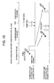
- the first combustion control pattern is selected in accordance with the water temperature at the time of starting as shown in Fig. 6. If the water temperature at the time of starting is equal to or higher than Tw (within a stratified combustion possible region), for the first combustion control pattern, the first fuel injection occurs during the compression stroke and the second fuel injection (injection of the additional fuel) occurs during the expansion stroke to raise the exhaust gas temperature by the afterburning of the additional fuel, thereby raising the temperature of the catalyst. On the other hand, if the water temperature at the time of starting is lower than Tw, the first fuel injection occurs during the intake stroke as shown in Fig. 15, and the ignition timing in addition to the uniform lean burn is retarded so as to approach the TDC, thereby providing the same effect.
- Tw stratified combustion possible region
- FIG. 7 A method for controlling fuel injection according to a typical embodiment of the present invention is shown in Fig. 7.
- the first fuel injection occurs during the compression stroke in both cases where the temperature of the catalyst is higher and lower than Tc
- the subsequent second fuel injection occurs during the early stage in the expansion stroke until the temperature of the catalyst reaches Tc, and occurs during the middle stage in the expansion stroke or later after the temperature of the catalyst reaches Tc.
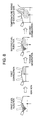
- a combustion mechanism will be described with reference to Fig. 8 in which the first fuel injection occurs during the compression stroke, and the second fuel injection occurs during the early stage in the expansion stroke.
- the first fuel injected during the compression stroke burns by the subsequent ignition.
- the second fuel injected during the early stage in the expansion stroke is ignited by the flame propagation of the first combustion.
- the temperature of the interior of the combustion chamber is extremely high when the second fuel injection occurs, so that the second injected fuel is insufficiently mixed with the residual oxygen in the combustion chamber and burns while taking in oxygen immediately after the injection.
- This is referred to as a diffusion combustion, and in such a combustion, a large amount of smoke is produced due to incomplete oxidation.
- Characteristics of the exhaust gas temperature, unburned HC, and smoke for varied timing of the second fuel injection are shown in Fig. 9. As the injection timing is delayed from 40 degATDC, the exhaust gas temperature is continuously reduced, and the unburned HC is continuously increased. Around 70 degATDC, there remains no flame of the main combustion, so that it is considered that the second injected fuel is difficult to be ignited. In addition, the smoke is rapidly increased before 40 degATDC.
- Fig. 10 is an illustration showing an optimum status of the second injected fuel injected during the early stage in the expansion stroke.
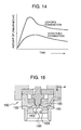
- (a) in Fig. 10 shows the case where a fuel injection valve capable of controlling the air and fuel separately is applied.
- the first fuel is injected during the compression stroke, and an air-fuel mixture concentratedly formed around the ignition plug is ignited by the ignition plug.
- the first fuel mentioned here may be the fuel only or mixture of the air and fuel.
- the application of the above-described fuel injection valve becomes effective in the second fuel injection. Since the second injected fuel which is injected during the early stage in the expansion stroke can be supplied to the combustion chamber in the form of the air and fuel mixed in advance, the combustion by the second injected fuel can be a premixed combustion.
- the injection valve 160 comprises a nozzle hole 163 located downstream from a valve element 161 and a valve seat 162, and a mixing chamber 164 for mixing the fuel with the air located downstream from the nozzle hole 163.
- FIG. 10 shows the case where a fuel injection valve capable of producing a fuel spray which is resistant to deformation caused by pressure changes is used.
- a fuel injection valve capable of producing a fuel spray which is resistant to deformation caused by pressure changes is used.
- an utilization rate of the residual oxygen in the combustion chamber can be increased and the unburned HC can be reduced without reduction in size of the fuel spray, so that as in the case of (a), the catalyst can be activated by the temperature rising of the exhaust gas while reducing the unburned HC and smoke.
- FIG. 17C An example of the injection valve 170 is shown in Fig. 17C.
- the injection valve 170 has a tip portion of a nozzle hole 171 cut stepwise 172 in the center of the nozzle hole 171 and mounted in such a manner that the cut side 173 faces the plug.
- An engine having the injection valve 170 configured in such a manner mounted thereon is shown in Fig. 17A.
- the fuel spray is deflected toward the plug as shown, and penetration is short and an amount of the fuel is small on the side of the piston.
- the cross-section of the fuel spray taken along the line XVIIB-XVIIB is shown in Fig. 17B.
- the center line is the line representing the cut face produced by cutting the nozzle hole stepwise 172.
- Such a spray has an advantage that it is resistant to deformation even if the pressure in the combustion chamber is high because the pressure is the same inside and outside the spray.
- Fig. 11 is an optimum fuel injection method in which the second fuel injection occurs during the early stage in the expansion stroke. More specifically, the method is a method in which the second injected fuel in the first combustion control before the temperature of the catalyst reaches Tc is divided and injected two or more times. By dividing and injecting the second injected fuel two or more times, the utilization rate of the residual oxygen is increased as described with reference to (b) of Fig. 10, so that the catalyst can be activated by the temperature rising of the exhaust gas while reducing the unburned HC and smoke.
- the second combustion control mentioned here refers to the method in which the second fuel injection occurs during the middle stage in the expansion stroke or later as shown in Fig. 11.
- the temperature of the catalyst has reached 250°C to 300°C when the second combustion control is started.
- the unburned HC after that begins reaction in the catalyst, and the calorific value is largely affected by the amount of the residual oxygen. If the amount of the residual oxygen in the exhaust gas isn't enough for the amount of the unburned HC exhausted from the combustion chamber, the unburned HC burns incompletely in the catalyst, and is discharged to the exhaust pipe on the downstream side of the catalyst.
- the pulse width of the second fuel injection is set on the basis of the concentration of oxygen in the exhaust gas.
- the pulse width of the second fuel injection is increased as the concentration of oxygen in the exhaust gas becomes higher.
- the fuel injection valve capable of separately controlling the air and the fuel as described with reference to (a) of Fig. 10 is preferably applied to supply only the air to the combustion chamber during the exhaust stroke, thereby ensuring the amount of oxygen in the exhaust gas corresponding to the amount of fuel required for activating the catalyst.
- the configuration and combustion control method as described above enable the time required for activating the catalyst to be substantially reduced in comparison with a conventional configuration and method.
- the catalyst is not activated, and therefore, the unburned HC exhausted from the combustion chamber is discharged into the atmosphere without being cleaned up.
- an optimum cylinder injection type internal combustion engine for providing the reduction of the unburned HC to be exhausted from the combustion chamber during the operation period from the cranking to the start of the first combustion control.
- Fig. 13 is a schematic perspective view of an optimum cylinder injection type internal combustion engine according to an embodiment of the present invention.
- This engine has essentially the same configuration as that shown in Fig. 1, except that distributor plates 17, each of which divides the intake flow path of the intake pipe 6 into two parts, that is, upper and lower parts, are provided in the respective intake pipes 6 on the upstream side of the intake valves 8, and flow dividing valves 18 are disposed upstream from the distributor plates 17.
- the flow dividing valve 18 is arranged in such a manner that the position of a valve element is changed within an angle range of 90° from a vertical position to a horizontal position by rotation of a valve stem.
- the velocity of a tumble flow 19 generated in the combustion chamber 5 is adjusted by opening and closing the flow dividing valve 18.
- a curved groove is formed on the top face of the piston 4 for rectifying the tumble flow 19 and enhancing the preservability thereof.
- the fuel injected from the fuel injection valve 10 is carried to the vicinity of the ignition plug by the tumble flow 19 generated in advance in the combustion chamber, and the stratified combustion can be provided at the time of cranking.
- an amount of the exhausted unburned HC can be substantially reduced compared with the uniform combustion.
- an amount of the air taken into the combustion chamber is small, so that the fuel injection valve which injects a part of the fuel spray toward the ignition plug is preferably used.
- the present invention provides a substantial reduction of the time required for activating the catalyst by switching over the combustion control based on the temperature of the catalyst between the first combustion control for raising the exhaust gas temperature while reducing the unburned HC and smoke and the second combustion control for supplying the unburned HC to the catalyst to burn the unburned HC in the catalyst.
- the stratified combustion can be provided at the time of starting, so that the unburned HC to be exhausted during the operation period from the cranking to the combustion control for the catalyst activation can be reduced.
Landscapes
- Engineering & Computer Science (AREA)
- Chemical & Material Sciences (AREA)
- Combustion & Propulsion (AREA)
- Mechanical Engineering (AREA)
- General Engineering & Computer Science (AREA)
- Electrical Control Of Air Or Fuel Supplied To Internal-Combustion Engine (AREA)
- Exhaust Gas After Treatment (AREA)
- Combustion Methods Of Internal-Combustion Engines (AREA)
- Fuel-Injection Apparatus (AREA)
- Combined Controls Of Internal Combustion Engines (AREA)
Applications Claiming Priority (2)
| Application Number | Priority Date | Filing Date | Title |
|---|---|---|---|
| JP2000097819 | 2000-03-30 | ||
| JP2000097819A JP2001280184A (ja) | 2000-03-30 | 2000-03-30 | 筒内噴射式内燃機関及び筒内噴射式内燃機関における始動時の燃焼制御方法 |
Publications (2)
| Publication Number | Publication Date |
|---|---|
| EP1138900A2 true EP1138900A2 (fr) | 2001-10-04 |
| EP1138900A3 EP1138900A3 (fr) | 2004-07-21 |
Family
ID=18612391
Family Applications (1)
| Application Number | Title | Priority Date | Filing Date |
|---|---|---|---|
| EP01106467A Withdrawn EP1138900A3 (fr) | 2000-03-30 | 2001-03-23 | Moteur à combustion à injection directe et procédé de commande de combustion au démarrage |
Country Status (3)
| Country | Link |
|---|---|
| US (1) | US20010027643A1 (fr) |
| EP (1) | EP1138900A3 (fr) |
| JP (1) | JP2001280184A (fr) |
Cited By (6)
| Publication number | Priority date | Publication date | Assignee | Title |
|---|---|---|---|---|
| EP1452712A1 (fr) * | 2003-02-21 | 2004-09-01 | Toyota Jidosha Kabushiki Kaisha | Contrôle de moteur diesel pour réaliser un échauffement rapide de catalyseur |
| FR2873163A1 (fr) * | 2004-07-15 | 2006-01-20 | Peugeot Citroen Automobiles Sa | Systeme de controle du fonctionnement d'un moteur diesel de vehicule automobile associe a un catalyseur d'oxydation |
| EP2163741A4 (fr) * | 2007-06-26 | 2015-06-03 | Isuzu Motors Ltd | Système de purification de no<sb>x</sb>et procédé pour commander un système de purification de no<sb>x</sb> |
| EP2857647A4 (fr) * | 2012-06-01 | 2016-01-13 | Toyota Motor Co Ltd | Dispositif de purification de gaz d'échappement pour moteur à combustion interne |
| EP3115586A4 (fr) * | 2014-03-05 | 2018-04-11 | Yanmar Co., Ltd. | Dispositif de commande d'injection de carburant pour moteur à combustion interne |
| CN111819356A (zh) * | 2018-01-23 | 2020-10-23 | 瓦锡兰芬兰有限公司 | 燃料喷射装置和操作活塞发动机的方法 |
Families Citing this family (8)
| Publication number | Priority date | Publication date | Assignee | Title |
|---|---|---|---|---|
| JP4632032B2 (ja) * | 2005-02-03 | 2011-02-16 | 三菱自動車工業株式会社 | 筒内噴射型火花点火式内燃機関 |
| JP4935904B2 (ja) * | 2007-07-04 | 2012-05-23 | トヨタ自動車株式会社 | 内燃機関の排気浄化システム |
| DE102008030898B4 (de) * | 2008-06-30 | 2010-07-01 | Ford Global Technologies, LLC, Dearborn | Steuereinrichtung für ein Kraftfahrzeug mit Verbrennungsmotor und Stopp-Start-Einrichtung |
| DE102010029728B4 (de) * | 2009-09-10 | 2022-06-02 | Robert Bosch Gmbh | Verfahren zur Steuerung einer Einspritzung von Kraftstoff in einen Verbrennungsmotor, Steuergerät zum Steuern einer Einspritzung in einem Verbrennungsmotor sowie Verfahren zum Auswählen eines Einspritzventils für ein Motorsystem |
| US9371790B2 (en) * | 2012-01-19 | 2016-06-21 | Ford Global Technologies, Llc | Methods and systems for controlling fuel injection |
| JP5787029B2 (ja) * | 2012-03-19 | 2015-09-30 | 日産自動車株式会社 | 内燃機関の点火時期制御装置 |
| GB2533376A (en) * | 2014-12-18 | 2016-06-22 | Gm Global Tech Operations Llc | A method of operating an internal combustion engine |
| WO2016166860A1 (fr) * | 2015-04-16 | 2016-10-20 | 日産自動車株式会社 | Dispositif et procédé de commande de moteur |
Family Cites Families (2)
| Publication number | Priority date | Publication date | Assignee | Title |
|---|---|---|---|---|
| US5482017A (en) * | 1995-02-03 | 1996-01-09 | Ford Motor Company | Reduction of cold-start emissions and catalyst warm-up time with direct fuel injection |
| AUPP070497A0 (en) * | 1997-12-03 | 1998-01-08 | Orbital Engine Company (Australia) Proprietary Limited | Improved method of fuelling an engine |
-
2000
- 2000-03-30 JP JP2000097819A patent/JP2001280184A/ja active Pending
-
2001
- 2001-02-28 US US09/794,208 patent/US20010027643A1/en not_active Abandoned
- 2001-03-23 EP EP01106467A patent/EP1138900A3/fr not_active Withdrawn
Cited By (12)
| Publication number | Priority date | Publication date | Assignee | Title |
|---|---|---|---|---|
| EP1452712A1 (fr) * | 2003-02-21 | 2004-09-01 | Toyota Jidosha Kabushiki Kaisha | Contrôle de moteur diesel pour réaliser un échauffement rapide de catalyseur |
| US6804952B2 (en) | 2003-02-21 | 2004-10-19 | Toyota Jidosha Kabushiki Kaisha | Catalyst warm up control for diesel engine |
| FR2873163A1 (fr) * | 2004-07-15 | 2006-01-20 | Peugeot Citroen Automobiles Sa | Systeme de controle du fonctionnement d'un moteur diesel de vehicule automobile associe a un catalyseur d'oxydation |
| WO2006016080A1 (fr) * | 2004-07-15 | 2006-02-16 | Peugeot Citroen Automobiles Sa | Systeme de controle du fonctionnement d'un moteur diesel de vehicule automobile associe a un catalyseur d'oxydation |
| US7823377B2 (en) | 2004-07-15 | 2010-11-02 | Peugeot Citroen Automobiles Sa | System for controlling the function of a diesel engine in a motor vehicle connected to an oxidation catalyst |
| EP2163741A4 (fr) * | 2007-06-26 | 2015-06-03 | Isuzu Motors Ltd | Système de purification de no<sb>x</sb>et procédé pour commander un système de purification de no<sb>x</sb> |
| EP2857647A4 (fr) * | 2012-06-01 | 2016-01-13 | Toyota Motor Co Ltd | Dispositif de purification de gaz d'échappement pour moteur à combustion interne |
| US9745877B2 (en) | 2012-06-01 | 2017-08-29 | Toyota Jidosha Kabushiki Kaisha | Exhaust gas purification apparatus for an internal combustion engine |
| EP3115586A4 (fr) * | 2014-03-05 | 2018-04-11 | Yanmar Co., Ltd. | Dispositif de commande d'injection de carburant pour moteur à combustion interne |
| US10612487B2 (en) | 2014-03-05 | 2020-04-07 | Yanmar Co., Ltd. | Fuel injection control device for internal combustion engine |
| CN111819356A (zh) * | 2018-01-23 | 2020-10-23 | 瓦锡兰芬兰有限公司 | 燃料喷射装置和操作活塞发动机的方法 |
| CN111819356B (zh) * | 2018-01-23 | 2022-02-25 | 瓦锡兰芬兰有限公司 | 燃料喷射装置和操作活塞发动机的方法 |
Also Published As
| Publication number | Publication date |
|---|---|
| US20010027643A1 (en) | 2001-10-11 |
| EP1138900A3 (fr) | 2004-07-21 |
| JP2001280184A (ja) | 2001-10-10 |
Similar Documents
| Publication | Publication Date | Title |
|---|---|---|
| JP3964387B2 (ja) | 圧縮着火式内燃機関の制御装置 | |
| JP4427744B2 (ja) | 直接燃料噴射式内燃機関の運転方法 | |
| KR101942876B1 (ko) | 내연기관의 시동 방법 | |
| JP4099396B2 (ja) | スパーク点火直噴内燃機関の排ガス温度を上昇させる方法 | |
| CN100398793C (zh) | 具有气体燃料喷射的内燃机 | |
| JP4689723B2 (ja) | 火花点火内燃機関の冷間運転のための方法 | |
| EP1138900A2 (fr) | Moteur à combustion à injection directe et procédé de commande de combustion au démarrage | |
| CN101405497A (zh) | 内燃机的燃料喷射控制装置和燃料喷射控制方法 | |
| CN107429625A (zh) | 直喷发动机的燃料喷射控制装置 | |
| JP3952710B2 (ja) | 圧縮自己着火式内燃機関 | |
| JP3257430B2 (ja) | 排気昇温装置 | |
| JP2005299530A (ja) | ディーゼルエンジン | |
| CN114233465B (zh) | 氨燃料燃烧系统、发动机及燃烧控制方法 | |
| JP3873560B2 (ja) | 内燃機関の燃焼制御装置 | |
| JP2004522899A (ja) | 内燃機関への流体の噴射を制御する方法 | |
| JP3912500B2 (ja) | 内燃機関 | |
| JP3743499B2 (ja) | 排気昇温装置 | |
| JP4010822B2 (ja) | 予混合圧縮自着火エンジン及びその起動運転方法 | |
| JP2002097960A (ja) | 内燃機関における燃焼方法 | |
| JP4967691B2 (ja) | ガソリンエンジンの制御装置 | |
| JP4618181B2 (ja) | 予混合圧縮自己着火型のガソリン内燃機関 | |
| JP2006183667A (ja) | 筒内噴射式内燃機関及び筒内噴射式内燃機関における始動時の燃焼制御方法 | |
| JP4609227B2 (ja) | 内燃機関 | |
| JP4572827B2 (ja) | 内燃機関の燃焼制御装置 | |
| JP4320345B2 (ja) | 直噴形エンジンの制御装置 |
Legal Events
| Date | Code | Title | Description |
|---|---|---|---|
| PUAI | Public reference made under article 153(3) epc to a published international application that has entered the european phase |
Free format text: ORIGINAL CODE: 0009012 |
|
| AK | Designated contracting states |
Kind code of ref document: A2 Designated state(s): AT BE CH CY DE DK ES FI FR GB GR IE IT LI LU MC NL PT SE TR |
|
| AX | Request for extension of the european patent |
Free format text: AL;LT;LV;MK;RO;SI |
|
| RIC1 | Information provided on ipc code assigned before grant |
Ipc: 7F 02D 41/30 B Ipc: 7F 02D 41/40 B Ipc: 7F 02D 37/02 B Ipc: 7F 02D 41/02 A |
|
| PUAL | Search report despatched |
Free format text: ORIGINAL CODE: 0009013 |
|
| AK | Designated contracting states |
Kind code of ref document: A3 Designated state(s): AT BE CH CY DE DK ES FI FR GB GR IE IT LI LU MC NL PT SE TR |
|
| AX | Request for extension of the european patent |
Extension state: AL LT LV MK RO SI |
|
| 17P | Request for examination filed |
Effective date: 20041112 |
|
| AKX | Designation fees paid |
Designated state(s): DE FR GB IT |
|
| STAA | Information on the status of an ep patent application or granted ep patent |
Free format text: STATUS: THE APPLICATION IS DEEMED TO BE WITHDRAWN |
|
| 18D | Application deemed to be withdrawn |
Effective date: 20051019 |