EP1138963A1 - Dispositif de maintien d'une gaine de commande à distance par câble - Google Patents
Dispositif de maintien d'une gaine de commande à distance par câble Download PDFInfo
- Publication number
- EP1138963A1 EP1138963A1 EP01107104A EP01107104A EP1138963A1 EP 1138963 A1 EP1138963 A1 EP 1138963A1 EP 01107104 A EP01107104 A EP 01107104A EP 01107104 A EP01107104 A EP 01107104A EP 1138963 A1 EP1138963 A1 EP 1138963A1
- Authority
- EP
- European Patent Office
- Prior art keywords
- cover
- base
- wall
- end piece
- support
- Prior art date
- Legal status (The legal status is an assumption and is not a legal conclusion. Google has not performed a legal analysis and makes no representation as to the accuracy of the status listed.)
- Granted
Links
- 238000000465 moulding Methods 0.000 claims abstract description 7
- 230000004323 axial length Effects 0.000 claims description 2
- 239000012815 thermoplastic material Substances 0.000 claims description 2
- 239000007787 solid Substances 0.000 abstract 1
- 238000010438 heat treatment Methods 0.000 description 4
- -1 polyethylene Polymers 0.000 description 4
- 238000004378 air conditioning Methods 0.000 description 3
- 238000009434 installation Methods 0.000 description 3
- 239000004033 plastic Substances 0.000 description 3
- 229920003023 plastic Polymers 0.000 description 3
- 239000004698 Polyethylene Substances 0.000 description 2
- 239000004743 Polypropylene Substances 0.000 description 2
- 239000004676 acrylonitrile butadiene styrene Substances 0.000 description 2
- 239000000463 material Substances 0.000 description 2
- 210000000056 organ Anatomy 0.000 description 2
- 229920000573 polyethylene Polymers 0.000 description 2
- 229920001155 polypropylene Polymers 0.000 description 2
- 229910000831 Steel Inorganic materials 0.000 description 1
- 229920000122 acrylonitrile butadiene styrene Polymers 0.000 description 1
- 230000000694 effects Effects 0.000 description 1
- 238000012423 maintenance Methods 0.000 description 1
- 238000000034 method Methods 0.000 description 1
- 239000011295 pitch Substances 0.000 description 1
- 239000010959 steel Substances 0.000 description 1
- 229920001169 thermoplastic Polymers 0.000 description 1
- 239000004416 thermosoftening plastic Substances 0.000 description 1
Images


Classifications
-
- F—MECHANICAL ENGINEERING; LIGHTING; HEATING; WEAPONS; BLASTING
- F16—ENGINEERING ELEMENTS AND UNITS; GENERAL MEASURES FOR PRODUCING AND MAINTAINING EFFECTIVE FUNCTIONING OF MACHINES OR INSTALLATIONS; THERMAL INSULATION IN GENERAL
- F16C—SHAFTS; FLEXIBLE SHAFTS; ELEMENTS OR CRANKSHAFT MECHANISMS; ROTARY BODIES OTHER THAN GEARING ELEMENTS; BEARINGS
- F16C1/00—Flexible shafts; Mechanical means for transmitting movement in a flexible sheathing
- F16C1/10—Means for transmitting linear movement in a flexible sheathing, e.g. "Bowden-mechanisms"
- F16C1/102—Arrangements to mount end fittings of the sheathings to support walls or brackets
- F16C1/105—Arrangements to mount end fittings of the sheathings to support walls or brackets to a slot in the bracket
-
- F—MECHANICAL ENGINEERING; LIGHTING; HEATING; WEAPONS; BLASTING
- F16—ENGINEERING ELEMENTS AND UNITS; GENERAL MEASURES FOR PRODUCING AND MAINTAINING EFFECTIVE FUNCTIONING OF MACHINES OR INSTALLATIONS; THERMAL INSULATION IN GENERAL
- F16C—SHAFTS; FLEXIBLE SHAFTS; ELEMENTS OR CRANKSHAFT MECHANISMS; ROTARY BODIES OTHER THAN GEARING ELEMENTS; BEARINGS
- F16C1/00—Flexible shafts; Mechanical means for transmitting movement in a flexible sheathing
- F16C1/10—Means for transmitting linear movement in a flexible sheathing, e.g. "Bowden-mechanisms"
- F16C1/22—Adjusting; Compensating length
- F16C1/226—Adjusting; Compensating length by adjusting the effective length of the sheathing
-
- F—MECHANICAL ENGINEERING; LIGHTING; HEATING; WEAPONS; BLASTING
- F16—ENGINEERING ELEMENTS AND UNITS; GENERAL MEASURES FOR PRODUCING AND MAINTAINING EFFECTIVE FUNCTIONING OF MACHINES OR INSTALLATIONS; THERMAL INSULATION IN GENERAL
- F16C—SHAFTS; FLEXIBLE SHAFTS; ELEMENTS OR CRANKSHAFT MECHANISMS; ROTARY BODIES OTHER THAN GEARING ELEMENTS; BEARINGS
- F16C1/00—Flexible shafts; Mechanical means for transmitting movement in a flexible sheathing
- F16C1/26—Construction of guiding-sheathings or guiding-tubes
- F16C1/262—End fittings; Attachment thereof to the sheathing or tube
-
- F—MECHANICAL ENGINEERING; LIGHTING; HEATING; WEAPONS; BLASTING
- F16—ENGINEERING ELEMENTS AND UNITS; GENERAL MEASURES FOR PRODUCING AND MAINTAINING EFFECTIVE FUNCTIONING OF MACHINES OR INSTALLATIONS; THERMAL INSULATION IN GENERAL
- F16B—DEVICES FOR FASTENING OR SECURING CONSTRUCTIONAL ELEMENTS OR MACHINE PARTS TOGETHER, e.g. NAILS, BOLTS, CIRCLIPS, CLAMPS, CLIPS OR WEDGES; JOINTS OR JOINTING
- F16B2200/00—Constructional details of connections not covered for in other groups of this subclass
- F16B2200/69—Redundant disconnection blocking means
-
- Y—GENERAL TAGGING OF NEW TECHNOLOGICAL DEVELOPMENTS; GENERAL TAGGING OF CROSS-SECTIONAL TECHNOLOGIES SPANNING OVER SEVERAL SECTIONS OF THE IPC; TECHNICAL SUBJECTS COVERED BY FORMER USPC CROSS-REFERENCE ART COLLECTIONS [XRACs] AND DIGESTS
- Y10—TECHNICAL SUBJECTS COVERED BY FORMER USPC
- Y10T—TECHNICAL SUBJECTS COVERED BY FORMER US CLASSIFICATION
- Y10T403/00—Joints and connections
- Y10T403/59—Manually releaseable latch type
-
- Y—GENERAL TAGGING OF NEW TECHNOLOGICAL DEVELOPMENTS; GENERAL TAGGING OF CROSS-SECTIONAL TECHNOLOGIES SPANNING OVER SEVERAL SECTIONS OF THE IPC; TECHNICAL SUBJECTS COVERED BY FORMER USPC CROSS-REFERENCE ART COLLECTIONS [XRACs] AND DIGESTS
- Y10—TECHNICAL SUBJECTS COVERED BY FORMER USPC
- Y10T—TECHNICAL SUBJECTS COVERED BY FORMER US CLASSIFICATION
- Y10T74/00—Machine element or mechanism
- Y10T74/20—Control lever and linkage systems
- Y10T74/20396—Hand operated
- Y10T74/20402—Flexible transmitter [e.g., Bowden cable]
- Y10T74/2045—Flexible transmitter [e.g., Bowden cable] and sheath support, connector, or anchor
Definitions
- the invention relates to mechanical remote controls by cable, in particular for vehicle equipment automobiles.
- It relates more particularly to a holding device a mechanical remote control cable duct, in which the sheath is provided with an end cap which is suitable for being maintained on a support.
- Such a remote control usually includes a sheath crossed by a cable which is movable in the sheath in axial direction. Cable has two ends which are subject respectively to an actuator and a mobile organ.
- the actuator is a rotary member of a control panel, while that the movable member is a component forming part of a vehicle heating and / or air conditioning system automobile.
- the sheath is provided with at least one of its ends, an end cap which is intended to be attached to a support, for example to a control unit. It is also possible that this end cap is located side of the movable member.
- the end piece is generally obtained by overmolding on the sheath and is intended to be secured to the support so that the corresponding end of the sheath is immobilized in a predefined position.
- the sheath is maintained on the support via an additional part such as a screw, clip, etc.
- the object of the invention is in particular to overcome the drawbacks cited above.
- It aims in particular to provide a device which allows to maintain such a control sheath by means of quick fixing, which requires no additional parts, nor special tools, and which also do not risk cause torsion of the sheath.
- the invention provides a device for maintaining the type defined above, which includes a fastener molding with the support and consisting of a base of the support to delimit a housing for receiving the nozzle and a cover connected to the base by a film hinge, so that this cover is clean to pivot between an open position for the introduction of tip and a locking position to trap the nozzle, and in which, in the locked position of the cover, the end cap is held in the housing by being immobilized axially and free in rotation.
- the invention provides a fastener made from a single piece with the support and essentially comprising a base from the support and a cover capable of pivot through a film hinge.
- This hinge allows you to let the sheath position during assembly by turning on itself because the end piece and the sheath are free to rotate.
- Such a hinge is produced by local thinning material between the base and the cover to provide a deformable area.
- the cover is suitable for pivoting relative to the base, while being monobloc with the latter.
- the cover is suitable for pivoting over an angular interval approximately 90 ° between the open position and the locking.
- the device of the invention advantageously comprises locking means for locking the cover on the base.
- these locking means include a tab integral with the cover and clean to be housed in an opening in the base in the locking position.
- the cover is provided internally a retaining stop located near the film hinge and suitable for coming into abutment behind an abutment flange formed at inside the base, when the cover is in position closing.
- the cover includes a shaped internal wall suitable for define a part of a cradle for receiving the nozzle.
- the base defines another part of this receiving cradle.
- the base includes a first wall to which the cover and a second wall opposite the first wall and suitable for cooperating with the cover for locking.
- this second wall is capable of flex elastically when locking the cover.
- the base comprises further two spaced side walls disposed between the first wall and the second wall to define a structure quadrangular.
- the two aforementioned side walls advantageously define an internal spacing which corresponds to the length axial of the nozzle.
- the two side walls form stops limiting movement axial of the nozzle.
- the tip can have different shapes. He can thus have a general form of revolution, in particular a general cylindrical shape, or even include a external thread.
- the support is advantageously formed by molding a thermoplastic material, in particular of the polyethylene type, polypropylene, ABS, etc.
- the attachment of the invention is defined so as to meet the pullout constraints imposed by the manufacturer.
- the need to resist tearing is due to the fact that in case of uncoupling of the sheath attachment and its mounting bracket, it becomes difficult to order a mobile organ. This is the case in particular in the order shutters of a heating and / or air conditioning installation of motor vehicle.
- the support is part of an equipment control box of motor vehicle.
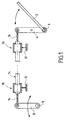
- Figure 1 shows an order remote mechanical by cable applied to the control of a equipment, in the example a shutter 2, which is integral in rotation of a lever 4 pivotally mounted about an axis 6.
- the lever 4 is controlled in rotation from an actuator 8, such as a rotary control member, rotatably mounted around an axis 9 and carried by a control unit (not shown).
- this control box is housed in a dashboard of a motor vehicle and component 2 is provided for management an air flow in a heating installation and / or vehicle interior air conditioning.
- the mechanical control of FIG. 1 comprises a sheath 14 crossed by a control cable 16, usually a single-strand or multi-strand cable made of steel, and this sheath is held by two holding devices 10, also called fasteners, according to the invention.
- the cable comprises a first end 11 forming a tip and secured to the actuator 8 and a second end 13 forming a nozzle and subject to the flap 2.
- the sheath 16 is held in the vicinity of its ends by two substantially identical holding devices 10 provided on the vehicle, i.e. respectively on the control unit and on the heating system and / or air conditioner.
- FIG. 2 shows one of the two aforementioned holding devices.
- This device includes a fastener 10 coming from molding with a support 12 (shown partially) consisting for example of a housing, such as the aforementioned control unit.
- the sheath 14 has a tip 18, in the example of shape general circular cylindrical, which is molded externally and which is intended to cooperate with the fastener 10.
- the fastener 10 is intended to hold this sheath in a position determined relative to the support 12 so as to immobilize it axially, while leaving it free rotation.
- This fastener 10 came from molding with the support 12, the assembly being made of a material suitable plastic, usually a thermoplastic, in particular of the polyethylene, polypropylene, ABS type, etc.
- the fastener 10 essentially consists of a base 20 from the support and a cover 22 connected to the base by a film hinge 24 so that the cover can pivot relative to the base around an articulation of axis X-X.
- the thickness is, for example, between 1/10 and 2/10 mm thick.
- the cover is suitable for pivot relative to the base between an open position as shown in Figure 2 to allow introduction of the nozzle between the base and the cover, and a position closing or locking in which the cover is folded down towards the base to jointly define a housing, of a shape adapted to that of the end piece, for keep the latter imprisoned, that is to say immobilized axially and free to rotate.
- the base 20 has a shape structure general quadrangular defining a kind of "chimney".
- the base 20 comprises a first wall 26 which is erected at from the support 12 and to which the cover 22 is connected by the film hinge 24.
- the cover 26 comprises, at opposite the film hinge 24, a shaped tab 28 chamfer, the function of which will be explained later.
- the base 20 further comprises a second opposite wall 30 to the first wall 26 and extending substantially parallel to this one.
- This second wall also stands at from support 12 but at a height greater than that of the wall 26.
- the wall 30 is hollowed out so as to define an opening or internal slot 32 delimited in particular by a rim 34 intended to cooperate with the tongue 28 to jointly form means for locking the cover relative to the base, as we will see later.
- the wall 30 is liable to flex relative to the support 12 so as to move away from the wall 26 in the direction arrow F ( Figures 4 and 9), as discussed below.
- the base 20 further comprises two spaced side walls 36 which are each arranged between the first wall 26 and the second wall 30 to define the quadrangular structure cited above.
- each of the walls 36 are each connected to the wall 26 but do not attach to the wall 30, to allow it to falter.
- each of the walls 36 has a longitudinal slot 38 which makes it possible to decouple the wall 30 side walls 36.
- the walls 36 are arranged opposite and provide between they have a spacing E (FIG. 5) which is substantially equal, by greater value, to the axial length L of the end piece 18. This accommodates the end piece between the two walls 36 for immobilize it in the axial direction, while leaving it free to rotate, even after closing the cover 22.
- each of the side walls 36 comprises a U-shaped recess 40 for receiving the sheath 14, on either side of the nozzle.
- the base 26 contributes to defining a housing, again called cradle, for receiving the tip of the sheath.
- the cover 22 (FIG. 4) comprises a branch 42 which constitutes the cover proper and which is extended by the tongue 28 and a branch 44 which extends in a general direction perpendicular to branch 42 towards the interior.
- This branch 44 is shaped to define on one side, and together with the branch 42, a housing 46 in the form of U for receiving the nozzle ( Figures 4 and 9). So in this position of opening the cover, the end piece 18 can to be received in this internal shaped wall 46, which defines part of a cradle for receiving the nozzle.
- the branch 44 defines a retaining stop 48 directed inward and located near the film hinge 24.
- This stop is suitable for bearing behind a stop flange 50 formed inside the base, on the side inside the wall 26.
- the stop 48 is able to cooperate with the stop flange 50 after pivoting of the cover.
- the cover thus passes through a multiplicity of positions intermediaries, one of which is shown in Figure 6.
- the cover has pivoted about 45 ° from the previous position. He has took with him the tip which is thus partly trapped between the cover 22 and the wall 30.
- the tip 18 of the sheath is trapped in the housing delimited by the base and the lid. It is held axially between the walls lateral 36 of the base and radially by the internal wall 46 of the cover as well as through the U-shaped recesses 40 of the walls 36 which surround the sheath on either side of the mouthpiece.
- the nozzle can be easily placed in the cover, in open position, then immobilized after pivoting of the cover relative to the base, up to the locking position, while keeping the possibility for the sheath to rotate on itself. So the device maintenance of the invention provides a pivot through which the end piece of the sheath and the sheath can rotate freely in avoiding any risk of twisting the sheath.
- the stop 48 comes in cooperation with the stop flange 50 which ensures security. Indeed, if the film hinge was damaged accidentally, the stopper and the stopper flange would cooperate between them to prevent the cover from coming off of the wall 26.
- such a fastener is intended to be actuated during a first assembly and possibly on occasion repair, so the film hinge is not intended to operate more than once.
- the tip has a generally cylindrical shape of revolution.
- the tip 18 is consisting of a simple cylinder.
- the tip 18 has an external thread 52 forming a thread.
- a similar end piece 18 'comprising a thread 52' in so that the screw pitches 52 and 52 'are reversed.
- the tip 18 has streaks 54, which provides an adjustment.
- the tip 18 has a shape of revolution and it includes a slot ring finger 56.
- the invention finds a preferential application to cable remote controls for equipment motor vehicles.
Landscapes
- Engineering & Computer Science (AREA)
- General Engineering & Computer Science (AREA)
- Health & Medical Sciences (AREA)
- Oral & Maxillofacial Surgery (AREA)
- Mechanical Engineering (AREA)
- Flexible Shafts (AREA)
- Connection Of Plates (AREA)
- Closures For Containers (AREA)
- Details Of Indoor Wiring (AREA)
- Supports For Pipes And Cables (AREA)
- Air Bags (AREA)
Abstract
Description
- la figure 1 représente une commande mécanique à distance par câble appliquée à la commande d'un équipement et comprenant une gaine maintenue par deux dispositifs de maintien selon l'invention ;
- la figure 2 est une vue en coupe d'un dispositif de maintien d'une gaine de commande à distance par câble, la gaine étant représentée avant introduction dans le dispositif ;
- la figure 3 est une vue de dessus correspondant à la figure 2 dans une phase ultérieure où le couvercle est en position d'ouverture ;
- la figure 4 est une vue en coupe selon la ligne IV-IV de la figure 3 ;
- la figure 5 est une vue en coupe selon la ligne V-V de la figure 4 ;
- la figure 6 est une vue analogue à la figure 4 dans une phase ultérieure, entre la position d'ouverture et une position de verrouillage du couvercle ;
- la figure 7 est une vue analogue à la figure 6 dans laquelle le couvercle est en position de verrouillage ;
- la figure 8 est une vue en coupe selon la ligne VIII-VIII de la figure 7 ;
- la figure 9 est une vue de côté correspondant à la figure 4 ; et
- les figures 10 à 13 sont des vues en coupe analogues à la figure 5 et correspondant à des embouts de formes différentes.
Claims (15)
- Dispositif de maintien d'une gaine de commande mécanique à distance par câble, ladite gaine étant munie d'un embout d'extrémité propre à être maintenue sur un support,
caractérisé en ce qu'il comprend une attache (10) venue de moulage avec le support (12) et constituée d'une embase (20) issue du support pour délimiter un logement de réception de l'embout et d'un couvercle (22) relié à l'embase par une charnière-film (24), de sorte que le couvercle est propre à pivoter entre une position d'ouverture pour l'introduction de l'embout et une position de verrouillage pour emprisonner l'embout, et en ce que, dans la position de verrouillage du couvercle, l'embout d'extrémité est maintenu dans le logement en étant immobilisé axialement et libre en rotation. - Dispositif selon la revendication 1, caractérisé en ce que le couvercle (22) est propre à pivoter sur un intervalle angulaire d'environ 90° entre la position d'ouverture et la position de verrouillage.
- Dispositif selon l'une des revendications 1 et 2, caractérisé en ce qu'il comprend des moyens de verrouillage (28, 34) pour verrouiller le couvercle (22) sur l'embase (20).
- Dispositif selon la revendication 3, caractérisé en ce que les moyens de verrouillage comprennent une languette (28) solidaire du couvercle (22) et propre à venir se loger dans une ouverture (32) de l'embase (20) dans la position de verrouillage.
- Dispositif selon l'une des revendications 1 à 4, caractérisé en ce que le couvercle (22) est muni intérieurement d'une butée de retenue (48) située proche de la charnière-film (24) et propre à venir en appui derrière un rebord de butée (50) formé à l'intérieur de l'embase (20), lorsque le couvercle est en position de verrouillage.
- Dispositif selon l'une des revendications 1 à 5, caractérisé en ce que le couvercle (22) comprend une paroi interne conformée (46) propre à définir une partie d'un berceau de réception de l'embout.
- Dispositif selon la revendication 6, caractérisé en ce que l'embase (20) définit une autre partie du berceau de réception de l'embout.
- Dispositif selon l'une des revendications 1 à 7, caractérisé en ce que l'embase (20) comprend une première paroi (26) à laquelle est reliée le couvercle (22) et une deuxième paroi (30) opposée à la première paroi et propre à coopérer avec le couvercle pour le verrouillage.
- Dispositif selon la revendication 8, caractérisé en ce que la deuxième paroi (30) est susceptible de fléchir élastiquement lors du verrouillage du couvercle.
- Dispositif selon l'une des revendications 8 et 9, caractérisé en ce que l'embase (20) comprend en outre deux parois latérales (36) espacées et disposées entre la première paroi (26) et la deuxième paroi (36) pour définir une structure quadrangulaire.
- Dispositif selon la revendication 10, caractérisé en ce que les deux parois latérales (36) de l'embase (20) définissent un espacement interne (E) qui correspond à la longueur axiale (L) de l'embout (18).
- Dispositif selon l'une des revendications 1 à 11, caractérisé en ce que l'embout (18) a une forme générale de révolution, en particulier une forme générale cylindrique.
- Dispositif selon l'une des revendications 1 à 11, caractérisé en ce que l'embout (18) comporte un filetage externe (52).
- Dispositif selon l'une des revendications 1 à 13, caractérisé en ce que le support (12) est formé par moulage d'une matière thermoplastique, en particulier .
- Dispositif selon l'une des revendications 1 à 14, caractérisé en ce que le support (12) fait partie d'un boítier de commande d'un équipement de véhicule automobile.
Applications Claiming Priority (2)
| Application Number | Priority Date | Filing Date | Title |
|---|---|---|---|
| FR0004150 | 2000-03-31 | ||
| FR0004150A FR2807120B1 (fr) | 2000-03-31 | 2000-03-31 | Dispositif de maintien d'une gaine de commande a distance par cable |
Publications (3)
| Publication Number | Publication Date |
|---|---|
| EP1138963A1 true EP1138963A1 (fr) | 2001-10-04 |
| EP1138963B1 EP1138963B1 (fr) | 2005-11-02 |
| EP1138963B8 EP1138963B8 (fr) | 2006-01-11 |
Family
ID=8848743
Family Applications (1)
| Application Number | Title | Priority Date | Filing Date |
|---|---|---|---|
| EP01107104A Expired - Lifetime EP1138963B8 (fr) | 2000-03-31 | 2001-03-22 | Dispositif de maintien d'une gaine de commande à distance par câble |
Country Status (6)
| Country | Link |
|---|---|
| US (1) | US6575051B2 (fr) |
| EP (1) | EP1138963B8 (fr) |
| JP (1) | JP2001317532A (fr) |
| DE (1) | DE60114493T2 (fr) |
| ES (1) | ES2250244T3 (fr) |
| FR (1) | FR2807120B1 (fr) |
Families Citing this family (9)
| Publication number | Priority date | Publication date | Assignee | Title |
|---|---|---|---|---|
| DE10156647B4 (de) * | 2001-11-17 | 2012-09-13 | Volkswagen Ag | Anschlußarmatur für einen Bowdenzugmantel |
| DE102004023867B3 (de) * | 2004-05-12 | 2005-11-24 | Küster Automotive Control Systems GmbH | Befestigungselement für einen Betätigungszug bzw. eine Schlauchfassung eines Betätigungszuges |
| GB2427904A (en) * | 2005-06-30 | 2007-01-10 | Hi Lex Cable System Company Lt | A mechanism for anchoring a Bowden cable |
| US20080105795A1 (en) * | 2006-11-03 | 2008-05-08 | Magna International Inc. | Cable retention feature |
| ATE522401T1 (de) * | 2009-04-03 | 2011-09-15 | Sika Technology Ag | Element zur abdichtung oder verstärkung eines hohlraumes und verfahren zur einbringung eines durchdringungselementes in ein solches element |
| FR2982304B1 (fr) | 2011-11-03 | 2013-12-06 | A Raymond Et Cie | Couvercle et bloc moteur pourvu dudit couvercle |
| US9109617B2 (en) | 2012-12-12 | 2015-08-18 | Newfrey Llc | Self-closing positive engagement clip |
| KR101439043B1 (ko) | 2013-07-24 | 2014-09-05 | 현대자동차주식회사 | 케이블 이완 방지 기구 및 이를 구비한 연료 도어 장치 |
| DE102015004766A1 (de) * | 2015-04-16 | 2016-10-20 | Klekert Aktiengesellschaft | Bowdenzuganbindung für ein Kraftfahrzeugschloss |
Citations (6)
| Publication number | Priority date | Publication date | Assignee | Title |
|---|---|---|---|---|
| FR2429922A1 (fr) * | 1978-06-26 | 1980-01-25 | Ferodo Sa | Dispositif de fixation d'une transmission par cable |
| US4452097A (en) * | 1981-07-16 | 1984-06-05 | Brose Fahrzeugteile Gmbh & Co. Kommanditgesellschaft | Tubular window drive mechanism particularly for motor vehicles |
| US4478381A (en) * | 1981-07-04 | 1984-10-23 | A. Raymond | Pipe clamp |
| DE4010992A1 (de) * | 1990-04-05 | 1991-10-10 | Kuester & Co Gmbh | Vorrichtung zur laengeneinstellung eines bowdenzugschlauches |
| US5590567A (en) * | 1995-03-14 | 1997-01-07 | Delco Electronics Corporation | Snap retainer and retainer system |
| DE29705650U1 (de) * | 1997-03-29 | 1997-06-12 | Behr Gmbh & Co, 70469 Stuttgart | Befestigungsvorrichtung für einen Bowdenzug |
Family Cites Families (11)
| Publication number | Priority date | Publication date | Assignee | Title |
|---|---|---|---|---|
| US3809371A (en) * | 1973-06-29 | 1974-05-07 | Master Fence Fittings Inc | Tension band |
| FR2247925A5 (fr) * | 1973-10-10 | 1975-05-09 | Itw De France | |
| US4386752A (en) * | 1981-03-13 | 1983-06-07 | General Motors Corporation | Hinged collar clip |
| JPS6030817A (ja) * | 1983-07-29 | 1985-02-16 | Toyota Motor Corp | ワイヤケ−ブルの取付け方法 |
| US4623102A (en) * | 1983-12-14 | 1986-11-18 | Apple Adhesives, Inc. | Article clamp |
| US4922783A (en) * | 1988-08-23 | 1990-05-08 | Wallace Dennis W | Cable clamping apparatus |
| US5260866A (en) * | 1991-09-17 | 1993-11-09 | Andersen Consulting | Expert configurator |
| US5855093A (en) * | 1993-06-30 | 1999-01-05 | Kuster & Co. | Cable-driven window lift |
| US5390876A (en) * | 1993-11-19 | 1995-02-21 | Sumitomo Denso Kabushiki Kaisha | Holder for fixing wiring harness and the like to automobile body |
| US5494245A (en) * | 1994-05-04 | 1996-02-27 | Yazaki Corporation | Wiring harness retainer clip |
| IT1286286B1 (it) * | 1996-03-29 | 1998-07-08 | Roltra Morse Spa | Dispositivo di fissaggio per un tirante di azionamento. |
-
2000
- 2000-03-31 FR FR0004150A patent/FR2807120B1/fr not_active Expired - Lifetime
-
2001
- 2001-03-22 EP EP01107104A patent/EP1138963B8/fr not_active Expired - Lifetime
- 2001-03-22 ES ES01107104T patent/ES2250244T3/es not_active Expired - Lifetime
- 2001-03-22 DE DE60114493T patent/DE60114493T2/de not_active Expired - Lifetime
- 2001-03-29 US US09/820,285 patent/US6575051B2/en not_active Expired - Lifetime
- 2001-04-02 JP JP2001103682A patent/JP2001317532A/ja active Pending
Patent Citations (6)
| Publication number | Priority date | Publication date | Assignee | Title |
|---|---|---|---|---|
| FR2429922A1 (fr) * | 1978-06-26 | 1980-01-25 | Ferodo Sa | Dispositif de fixation d'une transmission par cable |
| US4478381A (en) * | 1981-07-04 | 1984-10-23 | A. Raymond | Pipe clamp |
| US4452097A (en) * | 1981-07-16 | 1984-06-05 | Brose Fahrzeugteile Gmbh & Co. Kommanditgesellschaft | Tubular window drive mechanism particularly for motor vehicles |
| DE4010992A1 (de) * | 1990-04-05 | 1991-10-10 | Kuester & Co Gmbh | Vorrichtung zur laengeneinstellung eines bowdenzugschlauches |
| US5590567A (en) * | 1995-03-14 | 1997-01-07 | Delco Electronics Corporation | Snap retainer and retainer system |
| DE29705650U1 (de) * | 1997-03-29 | 1997-06-12 | Behr Gmbh & Co, 70469 Stuttgart | Befestigungsvorrichtung für einen Bowdenzug |
Also Published As
| Publication number | Publication date |
|---|---|
| FR2807120A1 (fr) | 2001-10-05 |
| ES2250244T3 (es) | 2006-04-16 |
| DE60114493D1 (de) | 2005-12-08 |
| US20010035066A1 (en) | 2001-11-01 |
| EP1138963B1 (fr) | 2005-11-02 |
| FR2807120B1 (fr) | 2002-06-21 |
| JP2001317532A (ja) | 2001-11-16 |
| US6575051B2 (en) | 2003-06-10 |
| EP1138963B8 (fr) | 2006-01-11 |
| DE60114493T2 (de) | 2006-08-03 |
Similar Documents
| Publication | Publication Date | Title |
|---|---|---|
| EP1147934B1 (fr) | Réservoir à carburant de véhicule automobile | |
| WO2009053640A1 (fr) | Agencement pour le montage d'un echangeur thermique sur un element de structure vertical formant une face avant technique de vehicule automobile | |
| EP1138963B1 (fr) | Dispositif de maintien d'une gaine de commande à distance par câble | |
| FR2904269A1 (fr) | Tubulure de remplissage du seservoir de carburant d'un vehicule automobile. | |
| EP2882056A1 (fr) | Cadre de montage pour l'encastrement d'une boîte électrique dans une paroi et ensemble comprenant un tel cadre de montage et une boîte électrique | |
| FR2746866A1 (fr) | Systeme et organe de fixation, notamment pour fixer des accessoires a des pieces de finition d'automobiles | |
| EP0497688B1 (fr) | Pare-soleil recouvert d'un revêtement et muni d'un bras de support | |
| EP0673806B1 (fr) | Dispositif de montage d'un pare-chocs sur la carrosserie d'un vehicule automobile. | |
| EP1021659B1 (fr) | Dispositif de commande a distance par cable pour equipement de vehicule automobile | |
| FR2760818A1 (fr) | Projecteur avec reflecteur reglable pour vehicule | |
| EP0798186B1 (fr) | Bras d'essuie-glace, notamment pour véhicule automobile | |
| EP2411250B1 (fr) | Dispositif antivol pour colonne de direction et procedes associes de montage d'un etrier de maintien | |
| FR2739816A1 (fr) | Projecteur pour vehicules | |
| EP3628877B1 (fr) | Dispositif d'ecrou encage pour un montage sur un montant creux | |
| FR2737691A1 (fr) | Retroviseur exterieur de vehicules automobiles | |
| EP2496864A1 (fr) | Levier de vitesse comportant un pommeau fixe de facon demontable sur la tige du levier | |
| EP1258389B1 (fr) | Dispositif d'obturation d'un orifice traversant une paroi et destiné à la fixation d'un objet, tel qu'un siège de véhicule automobile | |
| EP4334152A1 (fr) | Volet extrude pour dispositif d'obturation d'entree d'air de face avant de vehicule automobile | |
| EP3375675B1 (fr) | Capot, dispositif de connexion pour le montage d'un balai d'essuie-glace sur un bras d'essuie-glace et système d'essuyage correspondants | |
| EP2022921B1 (fr) | Dispositif de fixation d'une pièce à un support, tel qu'une vitre, du type à ècrou et vis | |
| FR2917452A1 (fr) | Systeme de liaison entre l'axe d'un volet roulant et une platine supportant l'axe | |
| EP0972675B1 (fr) | Elément de fixation intermédiaire pour le montage d'un élément sur une partie d'appui d'un projecteur de véhicule automobile | |
| EP1026044B1 (fr) | Ensemble de traversée de cloison | |
| FR2971565A1 (fr) | Systeme de fixation reglable formant entretoise. | |
| FR2889114A1 (fr) | Aerateur, notamment pour automobile, comprenant des ailettes de reglage pivotantes montees sur un corps rotatif |
Legal Events
| Date | Code | Title | Description |
|---|---|---|---|
| PUAI | Public reference made under article 153(3) epc to a published international application that has entered the european phase |
Free format text: ORIGINAL CODE: 0009012 |
|
| AK | Designated contracting states |
Kind code of ref document: A1 Designated state(s): AT BE CH CY DE DK ES FI FR GB GR IE IT LI LU MC NL PT SE TR |
|
| AX | Request for extension of the european patent |
Free format text: AL;LT;LV;MK;RO;SI |
|
| 17P | Request for examination filed |
Effective date: 20020305 |
|
| AKX | Designation fees paid |
Free format text: AT BE CH CY DE DK ES FI FR GB GR IE IT LI LU MC NL PT SE TR |
|
| GRAP | Despatch of communication of intention to grant a patent |
Free format text: ORIGINAL CODE: EPIDOSNIGR1 |
|
| RBV | Designated contracting states (corrected) |
Designated state(s): DE ES GB IT |
|
| GRAS | Grant fee paid |
Free format text: ORIGINAL CODE: EPIDOSNIGR3 |
|
| RAP1 | Party data changed (applicant data changed or rights of an application transferred) |
Owner name: VALEO CLIMATISATION |
|
| GRAA | (expected) grant |
Free format text: ORIGINAL CODE: 0009210 |
|
| AK | Designated contracting states |
Kind code of ref document: B1 Designated state(s): DE ES GB IT |
|
| PG25 | Lapsed in a contracting state [announced via postgrant information from national office to epo] |
Ref country code: GB Free format text: LAPSE BECAUSE OF FAILURE TO SUBMIT A TRANSLATION OF THE DESCRIPTION OR TO PAY THE FEE WITHIN THE PRESCRIBED TIME-LIMIT Effective date: 20051102 |
|
| REG | Reference to a national code |
Ref country code: GB Ref legal event code: FG4D Free format text: NOT ENGLISH |
|
| RAP2 | Party data changed (patent owner data changed or rights of a patent transferred) |
Owner name: VALEO SYSTEMES THERMIQUES |
|
| REF | Corresponds to: |
Ref document number: 60114493 Country of ref document: DE Date of ref document: 20051208 Kind code of ref document: P |
|
| REG | Reference to a national code |
Ref country code: ES Ref legal event code: FG2A Ref document number: 2250244 Country of ref document: ES Kind code of ref document: T3 |
|
| GBV | Gb: ep patent (uk) treated as always having been void in accordance with gb section 77(7)/1977 [no translation filed] |
Effective date: 20051102 |
|
| PLBE | No opposition filed within time limit |
Free format text: ORIGINAL CODE: 0009261 |
|
| STAA | Information on the status of an ep patent application or granted ep patent |
Free format text: STATUS: NO OPPOSITION FILED WITHIN TIME LIMIT |
|
| 26N | No opposition filed |
Effective date: 20060803 |
|
| PGFP | Annual fee paid to national office [announced via postgrant information from national office to epo] |
Ref country code: DE Payment date: 20170316 Year of fee payment: 17 |
|
| PGFP | Annual fee paid to national office [announced via postgrant information from national office to epo] |
Ref country code: IT Payment date: 20170315 Year of fee payment: 17 |
|
| PGFP | Annual fee paid to national office [announced via postgrant information from national office to epo] |
Ref country code: ES Payment date: 20170331 Year of fee payment: 17 |
|
| REG | Reference to a national code |
Ref country code: DE Ref legal event code: R119 Ref document number: 60114493 Country of ref document: DE |
|
| PG25 | Lapsed in a contracting state [announced via postgrant information from national office to epo] |
Ref country code: DE Free format text: LAPSE BECAUSE OF NON-PAYMENT OF DUE FEES Effective date: 20181002 |
|
| PG25 | Lapsed in a contracting state [announced via postgrant information from national office to epo] |
Ref country code: IT Free format text: LAPSE BECAUSE OF NON-PAYMENT OF DUE FEES Effective date: 20180322 |
|
| REG | Reference to a national code |
Ref country code: ES Ref legal event code: FD2A Effective date: 20190911 |
|
| PG25 | Lapsed in a contracting state [announced via postgrant information from national office to epo] |
Ref country code: ES Free format text: LAPSE BECAUSE OF NON-PAYMENT OF DUE FEES Effective date: 20180323 |