EP1138964A2 - Rouleau,en particulier rouleau en plastique - Google Patents
Rouleau,en particulier rouleau en plastique Download PDFInfo
- Publication number
- EP1138964A2 EP1138964A2 EP00128772A EP00128772A EP1138964A2 EP 1138964 A2 EP1138964 A2 EP 1138964A2 EP 00128772 A EP00128772 A EP 00128772A EP 00128772 A EP00128772 A EP 00128772A EP 1138964 A2 EP1138964 A2 EP 1138964A2
- Authority
- EP
- European Patent Office
- Prior art keywords
- rib
- roller
- barrel jacket
- ribs
- roll according
- Prior art date
- Legal status (The legal status is an assumption and is not a legal conclusion. Google has not performed a legal analysis and makes no representation as to the accuracy of the status listed.)
- Granted
Links
- 238000010521 absorption reaction Methods 0.000 description 5
- 230000005540 biological transmission Effects 0.000 description 4
- 238000001746 injection moulding Methods 0.000 description 3
- 239000000725 suspension Substances 0.000 description 3
- 229910000831 Steel Inorganic materials 0.000 description 2
- 230000008901 benefit Effects 0.000 description 2
- 238000009826 distribution Methods 0.000 description 2
- 239000000155 melt Substances 0.000 description 2
- 239000010959 steel Substances 0.000 description 2
- 230000007704 transition Effects 0.000 description 2
- TVEXGJYMHHTVKP-UHFFFAOYSA-N 6-oxabicyclo[3.2.1]oct-3-en-7-one Chemical compound C1C2C(=O)OC1C=CC2 TVEXGJYMHHTVKP-UHFFFAOYSA-N 0.000 description 1
- 230000009471 action Effects 0.000 description 1
- 230000015572 biosynthetic process Effects 0.000 description 1
- 230000000694 effects Effects 0.000 description 1
- 230000007774 longterm Effects 0.000 description 1
- 238000004519 manufacturing process Methods 0.000 description 1
- 238000005457 optimization Methods 0.000 description 1
- 238000005192 partition Methods 0.000 description 1
- 230000009467 reduction Effects 0.000 description 1
- 238000003860 storage Methods 0.000 description 1
Images

Classifications
-
- B—PERFORMING OPERATIONS; TRANSPORTING
- B65—CONVEYING; PACKING; STORING; HANDLING THIN OR FILAMENTARY MATERIAL
- B65G—TRANSPORT OR STORAGE DEVICES, e.g. CONVEYORS FOR LOADING OR TIPPING, SHOP CONVEYOR SYSTEMS OR PNEUMATIC TUBE CONVEYORS
- B65G1/00—Storing articles, individually or in orderly arrangement, in warehouses or magazines
- B65G1/02—Storage devices
- B65G1/023—Arrangements of article supporting rollers on racks
-
- B—PERFORMING OPERATIONS; TRANSPORTING
- B65—CONVEYING; PACKING; STORING; HANDLING THIN OR FILAMENTARY MATERIAL
- B65G—TRANSPORT OR STORAGE DEVICES, e.g. CONVEYORS FOR LOADING OR TIPPING, SHOP CONVEYOR SYSTEMS OR PNEUMATIC TUBE CONVEYORS
- B65G39/00—Rollers, e.g. drive rollers, or arrangements thereof incorporated in roller-ways or other types of mechanical conveyors
- B65G39/02—Adaptations of individual rollers and supports therefor
Definitions
- the invention relates to a role, in particular made of plastic, the inner, branched Stiffening ribs between the roller axis and the roller sleeve having.
- rollers or roller strips or roller conveyor strips formed from these usually come in flow racks for containers loaded with goods, e.g. Storage and / or transport boxes or boxes, for use.
- the shelf owns usual in several floors one above the other and in each floor to several juxtaposed, inclined raceways for the containers. Every career consists of roller conveyor strips that are spaced and in a row one behind the other
- Roller conveyor strips that are spaced and in a row one behind the other
- Have freely rotatable rollers or rollers which are usually used as cylindrical rollers or are designed as a flanged roller and are usually used in a mostly galvanized sheet steel profile to store.
- the rollers made of steel, preferably plastic, are the adapted to each load case and serve as support and guide elements for containers or boxes.
- roles are in manifold execution known, especially made of all-plastic Rollers that provide a force absorbing stiffening connection between the axle and have the barrel jacket.
- it is known to be straight in the interior of the roll casing running or additionally branched stiffening ribs made of plastic to arrange, with the aim of deformation of the barrel of the role, in particular in case of long-term stress, to avoid and thus the concentricity to ensure the role.
- a disadvantage of this stiffening design is the high risk of pressure the plastic roller in the event of a sudden impact load. This is particularly evident in one-piece rolls with plastic axes, the Impact on the barrel jacket is guided through the inner ribs to the axis and the axis may break.
- the invention has for its object a role of the type mentioned to create, which avoids these disadvantages and withstands high loads.
- the branched internal ribbing is provided with additional joints between one to the Barrel-connected connecting rib and one each from a central rib left and right fork ribs are formed.
- Central rib one to the right and one branching to the left
- fork rib which then each with a connecting rib the barrel jacket is connected.
- a preferred embodiment of the invention provides that the connecting rib to a tangent to the barrel jacket at a right angle runs.
- an increased force absorption of the connecting rib or ribs reached under loads on the barrel jacket.
- the right angle allows Arrangement on the barrel jacket an even distribution of the melt in the manufacturing process, which is preferably done by injection molding, whereby the barrel jacket undergoes a completely circular formation, which in particular the concentricity improved and thus to a smoother run the container to be conveyed leads.
- Another embodiment of the invention provides that two to each other diametrically arranged connecting ribs an imaginary line through the center of the roller describe. This ensures that a transmitted from the barrel jacket Force transmission via the connecting ribs, the fork ribs and the central rib centered on the center of the roll. This has the advantage that the roller axis evenly loaded and thus an axle break, especially in heavy Impacts on the barrel jacket is prevented.
- the Angular distances from connecting rib to connecting rib are approximately the same. Below that is both the angular distance between two connecting ribs Joint rib unit as well as the angular distance between two in the circumferential direction to understand spaced joint rib units. Because of the same Angular distances between the connecting ribs is one of these at each Force occurring point is recorded proportionally and over the subsequently attached ribs passed on or from the joints in the connection area the connecting ribs to the fork ribs absorbed. On the one hand this improves the concentricity of the roller barrel and on the other hand the even distribution of the melt during injection molding supported.
- the connecting rib and fork rib each include an internal angle ⁇ > 90 °.
- the Inner angle defines the enclosed area between the connecting rib and the fork rib.
- the invention provides that the connecting rib and fork rib under an outside angle ß> 180 ° are arranged.
- the inner angle ⁇ > 90 ° in combination with the outer angle ⁇ > 180 ° enables consequently, on the one hand, a greatly improved force absorption under loads overall Tread area of the role and the other much improved Concentricity of the roller barrel jacket, as it causes deformation Loads on the barrel jacket are extensively cushioned.
- the stiffening rib arrangement or the joint rib units consistently of one axial end face to the other axial end face of the roller, whereby a known medium stiffening surface with conventional rollers, which the Connects the tread over its entire circumference with the roller axis. A more extensive, shock-absorbing spring effect is thus achieved, since none medium stiffening surface or partition is more needed.
- Another embodiment of the invention is characterized by one each stiffening rib arrangement consisting of several joint rib units at each barrel jacket end, which are offset against each other.
- the individual joint rib units are based on the center of the roll and each to the barrel jacket ends - including the axial, open one Front side of the role is to be understood - extending towards and preferably 45 ° to each other produced twisted arranged.
- the one Barrel end up to the middle of the roller arranged joint rib units and of these supported barrel jacket areas on the other, opposite, in turn, a barrel jacket end that starts from the center of the roller and has no ribs Support area is opposite.
- this makes the spring action the ribs increased and thus the force absorption in the most varied Stress cases intensified.
- the offset against each other Rib arrangement ensures the greatest possible rigidity of the entire ribbing achieved and associated with it created an even more resilient plastic roller.
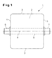
- a roller 1 shown in FIG. 1 belongs, for example, to one that is not shown here Roller track strip, the one behind the other in a row and in a row, has freely rotatable rollers.
- the roller 1, preferably made of plastic by injection molding, has one Roll body 2, which is formed with a barrel jacket 3.
- the reel body 2 has both its left barrel jacket end 4 and its right barrel jacket end 5 projecting journal 6, 7 one the center of the role 8 forming roller axis 9 (see FIGS. 2 and 3).
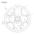
- the roller 1 is with a branched internal ribbing between the roller axis 9 and the barrel jacket 3.
- the ribbing is with Joints 10 executed, each between a tied to the barrel jacket 3 Connection rib 11 and one starting from a central rib 12 Fork rib 13 are formed.
- the connecting ribs 11 run approximately at a right angle to one Tangent 15 applied to the barrel jacket 3, which results in increased force absorption the connecting ribs 11 or the joint rib units 14 under loads of the barrel jacket 3 is reached.
- the connecting ribs 11 are arranged in such a way on the barrel jacket 3 that each two diametrically opposed ribs 11 an imaginary line 16 describe by the role center 8. This is done by the barrel jacket 3 transmitted force transmission centered on the roller center 8. Furthermore are the connecting ribs 11 at the same angular distances x, y on the barrel jacket 3 arranged. Because of the same angular distances x, y between the connecting ribs 11 of these one occurs at each point of the tread 3 Force absorbed proportionally and passed on via the following ribs or absorbed by the joints 10.
- the connecting ribs 11 and the fork ribs 13 are below the joints 10 an inner angle ⁇ > 90 ° connected to each other. This is the connection ribs 11 further spread outwards and thus support a larger area A. of the barrel jacket 3.
- the through the connecting ribs 11 and the fork ribs 13th of the joints 10 defined external angle ⁇ > 180 ° affects the between the joint rib units 14 lying free, unsupported surface B of the barrel jacket 3 and thus the desired resilient orientation of the connecting ribs 11 and the articulated ribs 13 under load.
Landscapes
- Engineering & Computer Science (AREA)
- Mechanical Engineering (AREA)
- Rolls And Other Rotary Bodies (AREA)
- Shaping Of Tube Ends By Bending Or Straightening (AREA)
- Lining Or Joining Of Plastics Or The Like (AREA)
Applications Claiming Priority (2)
| Application Number | Priority Date | Filing Date | Title |
|---|---|---|---|
| DE20006025U DE20006025U1 (de) | 2000-03-31 | 2000-03-31 | Rolle, insbesondere Kunststoffrolle |
| DE20006025U | 2000-03-31 |
Publications (3)
| Publication Number | Publication Date |
|---|---|
| EP1138964A2 true EP1138964A2 (fr) | 2001-10-04 |
| EP1138964A3 EP1138964A3 (fr) | 2002-10-09 |
| EP1138964B1 EP1138964B1 (fr) | 2005-08-03 |
Family
ID=7939671
Family Applications (1)
| Application Number | Title | Priority Date | Filing Date |
|---|---|---|---|
| EP00128772A Expired - Lifetime EP1138964B1 (fr) | 2000-03-31 | 2000-12-30 | Rouleau,en particulier rouleau en plastique |
Country Status (4)
| Country | Link |
|---|---|
| EP (1) | EP1138964B1 (fr) |
| AT (1) | ATE301251T1 (fr) |
| DE (2) | DE20006025U1 (fr) |
| ES (1) | ES2246795T3 (fr) |
Family Cites Families (5)
| Publication number | Priority date | Publication date | Assignee | Title |
|---|---|---|---|---|
| DE2430215C3 (de) | 1974-06-24 | 1978-11-16 | Fried. Krupp Gmbh, 4300 Essen | Verfahrbarer Lagerrahmen für schwere Maschinen oder Anlagen |
| DE8129856U1 (de) | 1981-10-13 | 1984-10-04 | Rubber- En Kunststoffabriek Enbi B.V., Nuth | Rolle, insbesondere transportrolle |
| DE9319394U1 (de) * | 1993-12-17 | 1994-02-10 | Bayerische Motoren Werke AG, 80809 München | Spannrolle für einen Riementrieb |
| ES2140811T3 (es) * | 1995-04-03 | 2000-03-01 | Baeltix Maskinfabrikken As | Conjunto de elementos modulares para la construccion de una polea de transmision para transportador de correas. |
| EP0928276B1 (fr) * | 1996-08-08 | 2001-11-14 | Flow Handling (Proprietary) Limited | Poulie folle |
-
2000
- 2000-03-31 DE DE20006025U patent/DE20006025U1/de not_active Expired - Lifetime
- 2000-12-30 ES ES00128772T patent/ES2246795T3/es not_active Expired - Lifetime
- 2000-12-30 DE DE50010870T patent/DE50010870D1/de not_active Expired - Lifetime
- 2000-12-30 EP EP00128772A patent/EP1138964B1/fr not_active Expired - Lifetime
- 2000-12-30 AT AT00128772T patent/ATE301251T1/de not_active IP Right Cessation
Also Published As
| Publication number | Publication date |
|---|---|
| DE50010870D1 (de) | 2005-09-08 |
| EP1138964B1 (fr) | 2005-08-03 |
| DE20006025U1 (de) | 2000-12-28 |
| ES2246795T3 (es) | 2006-03-01 |
| EP1138964A3 (fr) | 2002-10-09 |
| ATE301251T1 (de) | 2005-08-15 |
Similar Documents
| Publication | Publication Date | Title |
|---|---|---|
| DE10113510B4 (de) | Walzenkäfig, direkt wirkende Führungseinrichtung und Walzenschraube, die den Walzenkäfig verwendet | |
| DE3341970C2 (fr) | ||
| EP0472167A2 (fr) | Palier à contact de roulement pour mouvement linéaire, soit des rouleaux guidés sur rails | |
| DE3540099A1 (de) | Lineares gleitrollenlager | |
| DE3702238C2 (fr) | ||
| WO2012139701A1 (fr) | Palier oscillant | |
| DE4222175C2 (de) | Wälzlagerkäfig | |
| DE3153202C2 (de) | Linear-Rollenlager | |
| DD141340A5 (de) | Kugelbuchse fuer laengskugelfuehrungen | |
| DE19511999B4 (de) | Ausziehführung für Schubladen u. dgl. | |
| DE29917291U1 (de) | Wälzlager | |
| EP2530344B1 (fr) | Élément de roulement d'une articulation de trépied ainsi qu'articulation de trépied comprenant un tel élément de roulement | |
| DE102009034020A1 (de) | Wälzlager | |
| EP1138964B1 (fr) | Rouleau,en particulier rouleau en plastique | |
| DE102012222530A1 (de) | Wälzlager mit einem profilierten Wälzkörper | |
| AT517790B1 (de) | Gegossene achse für walze einer faserbahnmaschine und mit einer gegossenen achse ausgestattete walze | |
| DE102008004046A1 (de) | Käfig für Wälzkörper | |
| DE3430122A1 (de) | Federelement aus kunststoff | |
| EP1588066A1 (fr) | Cage de roulement | |
| DE19820039A1 (de) | Gelenkkette | |
| DE202012004522U1 (de) | Drehbarer Transportroller | |
| EP1106543B1 (fr) | Rouleau, notamment rouleau en matière plastique | |
| DE69807315T2 (de) | Verfahren zur herstellung einer kalenderwalze mit einem elastischen bezug und nach diesem verfahren hergestellte kalenderwalze | |
| EP0379885A1 (fr) | Rails de guidage télescopiques pour élévateur incliné ou d'échafaudage | |
| EP1516128B1 (fr) | Palier a roulement lineaire |
Legal Events
| Date | Code | Title | Description |
|---|---|---|---|
| PUAI | Public reference made under article 153(3) epc to a published international application that has entered the european phase |
Free format text: ORIGINAL CODE: 0009012 |
|
| AK | Designated contracting states |
Kind code of ref document: A2 Designated state(s): AT BE CH CY DE DK ES FI FR GB GR IE IT LI LU MC NL PT SE TR |
|
| AX | Request for extension of the european patent |
Free format text: AL;LT;LV;MK;RO;SI |
|
| PUAL | Search report despatched |
Free format text: ORIGINAL CODE: 0009013 |
|
| AK | Designated contracting states |
Kind code of ref document: A3 Designated state(s): AT BE CH CY DE DK ES FI FR GB GR IE IT LI LU MC NL PT SE TR |
|
| AX | Request for extension of the european patent |
Free format text: AL;LT;LV;MK;RO;SI |
|
| 17P | Request for examination filed |
Effective date: 20030308 |
|
| AKX | Designation fees paid |
Designated state(s): AT BE CH CY DE DK ES FI FR GB GR IE IT LI LU MC NL PT SE TR |
|
| GRAP | Despatch of communication of intention to grant a patent |
Free format text: ORIGINAL CODE: EPIDOSNIGR1 |
|
| GRAS | Grant fee paid |
Free format text: ORIGINAL CODE: EPIDOSNIGR3 |
|
| GRAA | (expected) grant |
Free format text: ORIGINAL CODE: 0009210 |
|
| AK | Designated contracting states |
Kind code of ref document: B1 Designated state(s): AT BE CH CY DE DK ES FI FR GB GR IE IT LI LU MC NL PT SE TR |
|
| PG25 | Lapsed in a contracting state [announced via postgrant information from national office to epo] |
Ref country code: IE Free format text: LAPSE BECAUSE OF FAILURE TO SUBMIT A TRANSLATION OF THE DESCRIPTION OR TO PAY THE FEE WITHIN THE PRESCRIBED TIME-LIMIT Effective date: 20050803 Ref country code: FI Free format text: LAPSE BECAUSE OF FAILURE TO SUBMIT A TRANSLATION OF THE DESCRIPTION OR TO PAY THE FEE WITHIN THE PRESCRIBED TIME-LIMIT Effective date: 20050803 Ref country code: TR Free format text: LAPSE BECAUSE OF FAILURE TO SUBMIT A TRANSLATION OF THE DESCRIPTION OR TO PAY THE FEE WITHIN THE PRESCRIBED TIME-LIMIT Effective date: 20050803 |
|
| REG | Reference to a national code |
Ref country code: GB Ref legal event code: FG4D Free format text: NOT ENGLISH |
|
| REG | Reference to a national code |
Ref country code: CH Ref legal event code: EP |
|
| REG | Reference to a national code |
Ref country code: IE Ref legal event code: FG4D Free format text: LANGUAGE OF EP DOCUMENT: GERMAN |
|
| REF | Corresponds to: |
Ref document number: 50010870 Country of ref document: DE Date of ref document: 20050908 Kind code of ref document: P |
|
| REG | Reference to a national code |
Ref country code: CH Ref legal event code: NV Representative=s name: SCHMAUDER & PARTNER AG PATENTANWALTSBUERO |
|
| PG25 | Lapsed in a contracting state [announced via postgrant information from national office to epo] |
Ref country code: SE Free format text: LAPSE BECAUSE OF FAILURE TO SUBMIT A TRANSLATION OF THE DESCRIPTION OR TO PAY THE FEE WITHIN THE PRESCRIBED TIME-LIMIT Effective date: 20051103 Ref country code: GR Free format text: LAPSE BECAUSE OF FAILURE TO SUBMIT A TRANSLATION OF THE DESCRIPTION OR TO PAY THE FEE WITHIN THE PRESCRIBED TIME-LIMIT Effective date: 20051103 Ref country code: DK Free format text: LAPSE BECAUSE OF FAILURE TO SUBMIT A TRANSLATION OF THE DESCRIPTION OR TO PAY THE FEE WITHIN THE PRESCRIBED TIME-LIMIT Effective date: 20051103 |
|
| GBT | Gb: translation of ep patent filed (gb section 77(6)(a)/1977) | ||
| PGFP | Annual fee paid to national office [announced via postgrant information from national office to epo] |
Ref country code: NL Payment date: 20051214 Year of fee payment: 6 |
|
| PGFP | Annual fee paid to national office [announced via postgrant information from national office to epo] |
Ref country code: CH Payment date: 20051215 Year of fee payment: 6 |
|
| PGFP | Annual fee paid to national office [announced via postgrant information from national office to epo] |
Ref country code: ES Payment date: 20051216 Year of fee payment: 6 |
|
| PGFP | Annual fee paid to national office [announced via postgrant information from national office to epo] |
Ref country code: FR Payment date: 20051219 Year of fee payment: 6 |
|
| PGFP | Annual fee paid to national office [announced via postgrant information from national office to epo] |
Ref country code: AT Payment date: 20051220 Year of fee payment: 6 |
|
| PGFP | Annual fee paid to national office [announced via postgrant information from national office to epo] |
Ref country code: GB Payment date: 20051222 Year of fee payment: 6 |
|
| PG25 | Lapsed in a contracting state [announced via postgrant information from national office to epo] |
Ref country code: CY Free format text: LAPSE BECAUSE OF FAILURE TO SUBMIT A TRANSLATION OF THE DESCRIPTION OR TO PAY THE FEE WITHIN THE PRESCRIBED TIME-LIMIT Effective date: 20051230 |
|
| PG25 | Lapsed in a contracting state [announced via postgrant information from national office to epo] |
Ref country code: MC Free format text: LAPSE BECAUSE OF NON-PAYMENT OF DUE FEES Effective date: 20051231 Ref country code: LU Free format text: LAPSE BECAUSE OF NON-PAYMENT OF DUE FEES Effective date: 20051231 |
|
| PG25 | Lapsed in a contracting state [announced via postgrant information from national office to epo] |
Ref country code: PT Free format text: LAPSE BECAUSE OF FAILURE TO SUBMIT A TRANSLATION OF THE DESCRIPTION OR TO PAY THE FEE WITHIN THE PRESCRIBED TIME-LIMIT Effective date: 20060103 |
|
| PGFP | Annual fee paid to national office [announced via postgrant information from national office to epo] |
Ref country code: BE Payment date: 20060116 Year of fee payment: 6 |
|
| REG | Reference to a national code |
Ref country code: ES Ref legal event code: FG2A Ref document number: 2246795 Country of ref document: ES Kind code of ref document: T3 |
|
| REG | Reference to a national code |
Ref country code: IE Ref legal event code: FD4D |
|
| ET | Fr: translation filed | ||
| PLBE | No opposition filed within time limit |
Free format text: ORIGINAL CODE: 0009261 |
|
| STAA | Information on the status of an ep patent application or granted ep patent |
Free format text: STATUS: NO OPPOSITION FILED WITHIN TIME LIMIT |
|
| 26N | No opposition filed |
Effective date: 20060504 |
|
| PG25 | Lapsed in a contracting state [announced via postgrant information from national office to epo] |
Ref country code: BE Free format text: LAPSE BECAUSE OF NON-PAYMENT OF DUE FEES Effective date: 20061231 Ref country code: LI Free format text: LAPSE BECAUSE OF NON-PAYMENT OF DUE FEES Effective date: 20061231 Ref country code: CH Free format text: LAPSE BECAUSE OF NON-PAYMENT OF DUE FEES Effective date: 20061231 |
|
| PGFP | Annual fee paid to national office [announced via postgrant information from national office to epo] |
Ref country code: IT Payment date: 20061231 Year of fee payment: 7 |
|
| PG25 | Lapsed in a contracting state [announced via postgrant information from national office to epo] |
Ref country code: NL Free format text: LAPSE BECAUSE OF NON-PAYMENT OF DUE FEES Effective date: 20070701 |
|
| REG | Reference to a national code |
Ref country code: CH Ref legal event code: PL |
|
| GBPC | Gb: european patent ceased through non-payment of renewal fee |
Effective date: 20061230 |
|
| NLV4 | Nl: lapsed or anulled due to non-payment of the annual fee |
Effective date: 20070701 |
|
| REG | Reference to a national code |
Ref country code: FR Ref legal event code: ST Effective date: 20070831 |
|
| PG25 | Lapsed in a contracting state [announced via postgrant information from national office to epo] |
Ref country code: AT Free format text: LAPSE BECAUSE OF NON-PAYMENT OF DUE FEES Effective date: 20061230 Ref country code: GB Free format text: LAPSE BECAUSE OF NON-PAYMENT OF DUE FEES Effective date: 20061230 |
|
| BERE | Be: lapsed |
Owner name: FRITZ *SCHAFER G.M.B.H. Effective date: 20061231 |
|
| REG | Reference to a national code |
Ref country code: ES Ref legal event code: FD2A Effective date: 20070102 |
|
| PG25 | Lapsed in a contracting state [announced via postgrant information from national office to epo] |
Ref country code: ES Free format text: LAPSE BECAUSE OF NON-PAYMENT OF DUE FEES Effective date: 20070102 Ref country code: FR Free format text: LAPSE BECAUSE OF NON-PAYMENT OF DUE FEES Effective date: 20070102 |
|
| PG25 | Lapsed in a contracting state [announced via postgrant information from national office to epo] |
Ref country code: IT Free format text: LAPSE BECAUSE OF NON-PAYMENT OF DUE FEES Effective date: 20071230 |
|
| PGFP | Annual fee paid to national office [announced via postgrant information from national office to epo] |
Ref country code: DE Payment date: 20191210 Year of fee payment: 20 |
|
| REG | Reference to a national code |
Ref country code: DE Ref legal event code: R071 Ref document number: 50010870 Country of ref document: DE |