EP1138969A1 - Einrichtung zur übertragung einer Drehbewegung mit einer Einweckupplung - Google Patents
Einrichtung zur übertragung einer Drehbewegung mit einer Einweckupplung Download PDFInfo
- Publication number
- EP1138969A1 EP1138969A1 EP01302845A EP01302845A EP1138969A1 EP 1138969 A1 EP1138969 A1 EP 1138969A1 EP 01302845 A EP01302845 A EP 01302845A EP 01302845 A EP01302845 A EP 01302845A EP 1138969 A1 EP1138969 A1 EP 1138969A1
- Authority
- EP
- European Patent Office
- Prior art keywords
- clutch
- peripheral surface
- diameter side
- side member
- axial direction
- Prior art date
- Legal status (The legal status is an assumption and is not a legal conclusion. Google has not performed a legal analysis and makes no representation as to the accuracy of the status listed.)
- Granted
Links
Images




Classifications
-
- F—MECHANICAL ENGINEERING; LIGHTING; HEATING; WEAPONS; BLASTING
- F16—ENGINEERING ELEMENTS AND UNITS; GENERAL MEASURES FOR PRODUCING AND MAINTAINING EFFECTIVE FUNCTIONING OF MACHINES OR INSTALLATIONS; THERMAL INSULATION IN GENERAL
- F16H—GEARING
- F16H55/00—Elements with teeth or friction surfaces for conveying motion; Worms, pulleys or sheaves for gearing mechanisms
- F16H55/32—Friction members
- F16H55/36—Pulleys
-
- F—MECHANICAL ENGINEERING; LIGHTING; HEATING; WEAPONS; BLASTING
- F16—ENGINEERING ELEMENTS AND UNITS; GENERAL MEASURES FOR PRODUCING AND MAINTAINING EFFECTIVE FUNCTIONING OF MACHINES OR INSTALLATIONS; THERMAL INSULATION IN GENERAL
- F16D—COUPLINGS FOR TRANSMITTING ROTATION; CLUTCHES; BRAKES
- F16D41/00—Freewheels or freewheel clutches
- F16D41/06—Freewheels or freewheel clutches with intermediate wedging coupling members between an inner and an outer surface
- F16D41/064—Freewheels or freewheel clutches with intermediate wedging coupling members between an inner and an outer surface the intermediate members wedging by rolling and having a circular cross-section, e.g. balls
- F16D41/066—Freewheels or freewheel clutches with intermediate wedging coupling members between an inner and an outer surface the intermediate members wedging by rolling and having a circular cross-section, e.g. balls all members having the same size and only one of the two surfaces being cylindrical
- F16D41/067—Freewheels or freewheel clutches with intermediate wedging coupling members between an inner and an outer surface the intermediate members wedging by rolling and having a circular cross-section, e.g. balls all members having the same size and only one of the two surfaces being cylindrical and the members being distributed by a separate cage encircling the axis of rotation
Definitions
- the present invention relates to an improvement in a rotation transmitting device incorporating a one-way clutch therein which can be used typically as a driven pulley fixed to an end of a rotary shaft of an alternator which serves as a power generator in a car, or a pinion fixed to an end of a rotary shaft for constituting a starter motor of a starting system of a car.
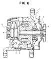
- Fig. 6 illustrates an alternator 1 which is described in the above application.
- a rotary shaft 3 is rotatably supported by a pair of rolling bearings 4 and 4 inside a housing 2.
- a rotor 5 and a rectifier 6 are provided in a middle part of this rotary shaft 3.
- a driven pulley 7 is fixed to an end portion (the right end portion in Fig. 6) of this rotary shaft 3 which is protruded outward from the housing 2.
- an endless belt is wound around this driven pulley 7 so that the rotary shaft 3 is driven to rotate freely by means of a crank shaft of the engine.
- Figs. 7 to 9 illustrate a pulley device incorporating a one-way clutch conventionally known by being described in either of the above publications.
- This pulley device incorporating a one-way clutch therein comprises a sleeve 8 which serves as an inner diameter side member and can be fitted and fixed onto the rotary shaft 3 of the alternator 1 (see Fig. 6).
- a driven pulley 7a which serves as an outer diameter side member in a cylindrical form to be concentric with this sleeve 8.
- a pair of support bearings 9, 9 and a roller clutch 10 serving as the one-way clutch are provided between the outer peripheral surface of the sleeve 8 and the inner peripheral surface of the driven pulley 7a.
- the sleeve 8 is formed to be cylindrical as a whole, and is fitted and fixed onto an end portion of the rotary shaft 3 of the alternator 1 to be rotatable with this rotary shaft 3.
- a threaded hole portion 11 is formed in a middle part on the inner peripheral surface of the sleeve 8, and this threaded hole portion and a male screw portion which is formed on the outer peripheral surface at the tip end portion of the rotary shaft 3 are arranged to be thread-engaged with each other.
- a latch hole portion 12 having a hexagonal cross section is also formed at the tip end portion on the inner peripheral surface of the sleeve 8 (the left end portion in Fig. 7).
- the tip end portion of a tool such as a hexagonal wrench can be latched by this latch hole portion 12.
- the base portion (the right end portion in Fig. 7) of the inner peripheral surface of the sleeve 8 serves as a circular hole portion 13 which can be fitted on a portion near the middle part of the tip end portion of the rotary shaft 3 with no play.
- a spline engagement, non-circular fitting, key engagement, or another arrangement may be employed as the arrangement for combining the sleeve 8 with the rotary shaft 3 in such a manner that they are not relatively rotated with each other.
- the central portion of the outer peripheral surface of the sleeve 8 serves as a large diameter portion 14 which has a larger diameter size than that of another portion.
- a tip half portion of the outer peripheral surface of the driven pulley 7a has a cross section in a waveform along the widthwise direction, around which a part of the endless belt called a poly-V belt can be wound.
- the above-mentioned roller clutch 10 is disposed in a middle part in the axial direction of a space existing between the outer peripheral surface of the sleeve 8 and the inner peripheral surface of the driven pulley 7a, while the support bearings 9, 9 are respectively disposed at positions to sandwich this roller clutch 10 from the both sides in the axial direction near the both ends of this space in the axial direction.
- the support bearings 9, 9 allow, while supporting a radial load applied on the driven pulley 7a, a relative rotation between this driven pulley 7a and the sleeve 8.
- ball bearings of a deep groove type are used as the support bearings 9, 9. More specifically, these support bearings 9, 9 comprise outer races 16, 16 respectively having outer raceways 15, 15 of the deep groove type on the respective inner peripheral surfaces thereof, inner races 18, 18 respectively having inner raceways 17, 17 of the deep groove type on the respective outer peripheral surfaces thereof, and balls 19, 19 provided in plural sets as capable of rolling between the outer raceways 15, 15 and the inner raceways 17, 17.
- the outer races 16, 16 are fitted and fixed onto the inner peripheral surface near the both ends of the driven pulley 7a, while the inner races 18, 18 are onto the outer peripheral surfaces near the both ends of the sleeve 8, respectively.
- the inner races 18, 18 in the axial direction are brought into contact with the respective end surfaces (step surfaces) in the axial direction of the large diameter portion 14.
- seal rings 20, 20 are provided between the inner peripheral surfaces of the both end portions of the outer races 16, 16 and the outer peripheral surfaces of the both end portions of the inner races 18, 18, respectively, thereby sealing openings at the both ends of the space provided with the balls 19, 19 described above.
- a communication hole is formed in a part of each of the seal rings 20, 20 on the side facing a space which is formed by and between the support bearings 9, 9, out of the above-described seal rings 20, 20, so that this space and the space receiving therein the balls 19, 19 of the support bearings 9, 9 are communicated to each other, in order to prevent excessive rise of the pressure inside the space formed by and between the support bearings 9, 9 when the support bearings 9, 9 are inserted with pressure between the inner peripheral surface of the driven pulley 7a and the outer peripheral surface of sleeve 8.
- the roller clutch 10 is arranged to allow transmission of the force of rotation between the driven pulley 7a and the sleeve 8 only when the driven pulley 7a has a tendency to rotate in a predetermined direction relatively to the sleeve 8.
- the clutch inner race 21 is interference-fitted and fixed onto the large diameter portion 14 of the sleeve 8.
- This clutch inner race 21 is formed to be cylindrical as a whole by press working, or other plastic working, of a steel plate of, for instance, cemented steel, and on the outer surface of which, a cam surface 22 is formed.
- a plurality of concave portions 23, 23 each called a ramp portion are formed on the outer peripheral surface of the clutch inner race 21 at regular intervals in the circumferential direction, whereby the outer peripheral surface serves as the cam surface 22 mentioned above.
- a concave chamfered portion 24 is formed on one end portion (the left end portion in Fig. 7) on the inner peripheral surface of the clutch inner race 21, and this chamfered portion 24 serves as a guide surface when the clutch inner race 21 is to be thrust with pressure into the outer peripheral surface of the large diameter portion 14.
- clutch outer race 25 which is interference-fitted and fixed in the middle part on the inner peripheral surface of the driven pulley 7a, at least a middle part in the axial direction in contact with rollers 26, which is described later, is simply formed as a cylindrical surface.
- Such clutch outer race 25 is formed to be cylindrical as a whole also by press working or other plastic working of a steel plate of, for instance, cemented steel, and inward flange portions 27a and 27b are formed at the both ends of the clutch outer race 25 in the axial direction. Note that one flange portion 27a (the left one in Fig.
- a plurality of rollers 26 for constituting the roller clutch 10 together with the clutch inner race 21 and the clutch outer race 25 are supported to allow a slight displacement in the rolling and circumferential directions by a clutch retainer 28 which is fitted on the clutch inner race 21 to allow no rotation with respect to the clutch inner race 21.
- This clutch retainer 28 is formed in a cylindrical form of a cage type as a whole of synthetic resin (for instance, synthetic resin of polyamide 66, polyamide 46, polyphenylene sulfide, or the like, mixed with 20% of glass fiber).
- This clutch retainer 28 is provided with a pair of rim portions 29, 29 each formed in an annular shape, and a plurality of column portions 30, 30 for connecting the both rim portions 29, 29 to each other.
- Portions surrounded on the four sides by the inner side surfaces of the rim portions 29, 29 and the side surfaces of the column portions 30, 30 in the circumferential direction are called the pockets 31, 31 for holding the rollers 26 to allow a slight displacement in the rolling and circumferential directions. Then, arcuate convex portions 32, 32 which are formed at a plurality of positions on the inner peripheral surfaces of the rim portions 29, 29 are engaged with the concave portions 23, 23 formed on the outer peripheral surface of the clutch inner race 21, whereby the clutch retainer 28 is attached to the clutch inner race 21 in such a manner that a relative rotation with this clutch inner race 21 is not allowed.
- leaf springs or springs each typically made of a synthetic resin and integrally formed with this clutch retainer 28. These springs elastically press the respective rollers 26 in the same direction with respect to the circumferential direction of the clutch retainer 28 toward a portion, out of a cylindrical gap formed between the outer peripheral surface of the cam surface 22 and the inner peripheral surface (cylindrical surface) of a middle part of the clutch outer race 25, which is narrower in the radial direction.
- each roller 29 enters into the narrower portion in the radial direction of the cylindrical gap, whereby the relative rotation between the driven pulley 7a and the sleeve 8 becomes impossible (in a locked state).
- each of the rollers 26 is retracted to a portion having the greater width in the radial direction of the cylindrical gap, thereby allowing the relative rotation between the driven pulley 7a and the sleeve 8 (in an over-run state).
- the pulley device incorporating a one-way clutch for an alternator having a structure as described above there are two reasons for employing the pulley device incorporating a one-way clutch for an alternator having a structure as described above, as described below.
- the first reason is to prolong the life of the endless belt. For instance, by the use of a diesel engine as the driving engine, a fluctuation in angular speed of rotation of the crank shaft becomes great at the time of low rotation such as an idling time.
- the running speed of the endless belt which is wound around the driving pulley fluctuates finely
- the rotary shaft 3 of the alternator which is driven to rotate through the driven pulley by the use of this endless belt does not fluctuate so rapidly owing to the inertia masses of the rotary shaft 3 and a rotor, or the like, fixed to this rotary shaft 3.
- the endless belt and the driven pulley are inclined to rub each other in the both directions upon a fluctuation in the angular speed of rotation of the crank shaft.
- the stress works on the endless belt which rubs this driven pulley repeatedly in different directions, to easily cause a slip between this endless belt and the driven pulley, or to reduce the life of this endless belt.
- the pulley device incorporating a one-way clutch for an alternator having a structure as described above as the driven pulley described above, it is arranged such that the force of rotation can be transmitted from the driven pulley to the rotary shaft 3 when the running speed of the endless belt is fixed or on the increase, while the relative rotation is allowed between the driven pulley and the rotary shaft 3 when the running speed of the endless belt is on the decrease.
- the angular speed of rotation of the driven pulley is set to be slower than the angular speed of rotation of the rotary shaft so as to prevent strong friction between the endless belt and the driven pulley in a contact portion therebetween.
- the direction of the stress acting on the frictional portion between the driven pulley and the endless belt is fixed so as to prevent a slip between this endless belt and the driven pulley or reduction of the life of this endless belt.
- the second reason is to enhance the efficiency in power generation by the alternator.
- the rotary shaft 3 to which the rotor of the alternator is fixed is driven to rotate by the driving engine of the car through the endless belt and the driven pulley.
- a driven pulley of a fixed type is used, if the speed of rotation of the driving engine is rapidly decreased, the speed of rotation of the rotor is also rapidly decreased, whereupon an amount of power generation by the alternator also rapidly decreases.
- the displacement of the clutch retainer 28 in the axial direction is prevented by the paired flange portions 27a, 27b which are provided at the both ends of the clutch outer race 25. More specifically, when the clutch retainer 28 is to be displaced in the axial direction at the time of over-run at which the driven pulley 7a and the sleeve 8 are rotated relatively to each other, an end surface in the axial direction of this clutch retainer 28 and the inner side surface of one 27a (or 27b) of the paired flange portions are brought into contact (sliding contact) to prevent the displacement in the axial direction of the clutch retainer 28.
- a relative speed of rotation between the pulley 7a and the sleeve 8 may reach several hundred min -1 (r.p.m.) to several thousand min -1 (r.p.m.) in an extreme case.
- both end surfaces in the axial direction of the clutch retainer 28 and the inner side surfaces of the flange portions 27a, 27b are brought into sliding contact as described above, the both end surfaces in the axial direction of the clutch retainer 28 may be easily worn away, or a frictional heat which is generated in the sliding contact portions between the both end surfaces in the axial direction of this clutch retainer 28 and the inner side surfaces of the flange portions 27a, 27b may be excessively high.
- the rotation transmitting device incorporating a one-way clutch therein according to the present invention has been contrived taking the circumstances as described above into consideration.
- a rotation transmitting device incorporating a one-way clutch therein which comprises, an inner diameter side member fixed to an end of a rotary shaft, an outer diameter side member in a cylindrical form disposed around the inner diameter side member to be concentric with the inner diameter side member, a one-way clutch disposed between a middle part in the axial direction on the outer peripheral surface of the inner diameter side member and a middle part in the axial direction on the inner peripheral surface of the outer diameter side member for transmitting rotation between the outer diameter side member and the inner diameter side member only when the outer diameter side member has a tendency to relatively rotate in a predetermined direction with respect to the inner diameter side member, and a pair of support bearings disposed between the outer peripheral surface of the inner diameter side member and the inner peripheral surface of the outer diameter side member at a position to pinch this one-way clutch from the both sides thereof in the axial direction for allowing a relative rotation between the inner diameter side member and the outer diameter side member while supporting a radial load applied on this outer diameter side member
- a clutch retainer for constituting the one-way clutch is arranged, based on that a part of the peripheral surface of this clutch retainer is brought into engagement directly or through another member with either one of the inner peripheral surface of the outer diameter side member and the outer peripheral surface of the inner diameter side member, to be rotated together with a member disposed on the one peripheral surface.
- a convex portion formed in a protruding manner toward the above one peripheral surface at an end portion in the axial direction of the clutch retainer is disposed between a step surface formed on the above one peripheral surface or an end surface in the axial direction of a member fitted and fixed on this one peripheral surface and another step surface formed on the one peripheral surface or an end surface in the axial direction of the other member fitted and fixed to this one peripheral surface so as to regulate a displacement of the clutch retainer in the axial direction, thereby preventing the both end surfaces of this clutch retainer in the axial direction from contacting with a member which is rotated relatively to this clutch retainer.
- a clutch outer race having a pair of flanges extending inward in the radial direction at the both ends in the axial direction thereof may be fitted and fixed into a middle part of the outer diameter side member in the axial direction with one of the peripheral surfaces serving as the outer peripheral surface of the inner diameter side member, and the inner side surfaces of the flanges which are opposited to each other may be approximated to face the both end surfaces in the axial direction of the clutch retainer.
- the step surface and the end surface are portions rotating with the clutch retainer, the step surface and the end surface do not rub the contact portion of the convex portion when the one-way clutch overruns.
- the rotation transmitting device incorporating a one-way clutch therein there is no possibility of abrasion of the both end surfaces in the axial direction of the clutch retainer or generation of frictional heat on the both end surfaces in the axial direction of the clutch retainer.
- the abraded powder of the clutch retainer is not mixed into the grease for lubricating the one-way clutch, or this grease is not deteriorated by the heat. Consequently, it is possible to realize a rotation transmitting device incorporating a one-way clutch therein which maintains the state of lubrication of the one-way clutch over a long term satisfactorily and has a sufficient durability.
- the structure may be arranged such that a gap is present all the time between the inner side surfaces of the paired round wheel portions formed at the both end portions in the axial direction of the clutch outer race and the both end surfaces in the axial direction of the clutch retainer.
- this gap portion may be used as a grease pool, so as to conduct lubrication of the one-way clutch satisfactorily. More specifically, when the rotation transmitting device incorporating a one-way clutch therein is used, the centrifugal force acts upon the grease which is thick on the gap portion. Then, the grease thus receiving the centrifugal force is diffused uniformly on the inner peripheral surface of the clutch outer race.
- Fig. 1 shows a first embodiment of the present invention.
- the present invention is characterized in that a displacement in the axial direction of a clutch retainer 28a is restricted to prevent the contact (sliding contact) between the both end surfaces in the axial direction of the clutch retainer 28a and the inner side surfaces of a pair of flange portions 27a, 27b for constituting a clutch outer race 25.
- Other structures and operations are the same as those of the conventional structure shown in Figs.
- a step surface 33 is formed on the outer peripheral surface of a part near an end (the portion near the left end portion in Fig. 1) of a large diameter portion 14 which is provided in a middle part in the axial direction of the sleeve 8, by protruding the outer peripheral surface of an end portion of this large diameter portion 14 outwardly in the radial direction.
- a convex portion 34 protruding inward in the radial direction is formed along the entire circumference thereof, or at least at one position in the circumferential direction.
- the dimensions of the respective members are so regulated that, when the clutch retainer 28a has a tendency to displace in the axial direction, the side surface of the convex portion 34 and the step surface 33 described above or one of the end surfaces of the clutch inner race 21 are brought into contact, so as to avoid the contact between the end surface in the axial direction of this clutch retainer 28a and the inner side surface of one 27a (or 27b) of the paired flange portions.
- the values for A to C are set to satisfy the relation C > B - A, taking an error in assembly and the assembling performance into consideration. For instance, when a difference B - A is 0 to 0. 5 (mm), the distance C is set to be larger than 0. 05 (mm). Note that the step surface 33 and the end surface of the clutch inner race 21 are the portions rotating together with the clutch retainer 28a.
- the object of the present invention can be attained by satisfying the relation C > (B -A) / 2. In this case, however, it should be arranged such that the distances C between the clutch retainer 28a and the flange portions 27a, 27b are equal to each other in a state in which the convex portion 34 is disposed at a neutral position in the direction of displacement.
- a gap is present all the time between the inner side surface of each of the paired flange portions 27a, 27b and each of the end surfaces in the axial direction of the clutch retainer 28a. For this reason, this gap portion is used as a grease pool so that lubrication of the roller clutch 10 can be conducted sufficiently. That is, when the pulley device incorporating a one-way clutch is used, the centrifugal force works on the grease which gathers in this gap portion. Then, the grease thus receiving the centrifugal force is diffused uniformly over the inner peripheral surface of the clutch outer race 25.
- the grease can be fully supplied into the spaces between the rolling surfaces of a plurality of rollers 26 for constituting the roller clutch 10 and the inner peripheral surface of the clutch outer race 25, which spaces are parts requiring the grease at the time of overrun at which the driven pulley 7a and the sleeve 8 are rotated relatively to each other.
- a pulley device incorporating a one-way clutch which maintains the state of lubrication of the roller clutch 10 excellently over a long term and has a sufficient durability.
- this convex portion 34 is disposed on one end side of the clutch retainer 28a in the foregoing embodiment, this convex portion 34 may be disposed on the other end side (the right end side in Fig. 1) of the clutch retainer 28a.
- Figs. 2 to 3 show second and third embodiments of the present invention.
- the step surface 33 (see Fig. 1) is not provided on the outer peripheral surface near the end (the left end in Figs. 2 and 3) of the large diameter portion 14 which constitutes the sleeve 8a, and the outer peripheral surface of this large diameter portion 14 is formed in a simple cylindrical shape along the entire length in the axial direction.
- an annular restricting member 36 having a rectangular cross section is interference-fitted and fixed typically onto a part which is near one end of the outer peripheral surface of the sleeve 8a and adjacent to the large diameter portion 14 (in case of the second embodiment shown in Fig.
- the convex portion 34 (see Fig. 1) of the clutch retainer 28a is disposed between the end surface (the right end surface in Figs. 2 and 3) in the axial direction of this restricting member 36 and the end surface (the left end surface in Fig. 1) in the axial direction of the clutch inner race 21 (see Fig. 1) which is fitted and fixed onto the large diameter portion 14.
- the outer peripheral surface of the large diameter portion 14 can be formed in a simple cylindrical shape along the entire length in the axial direction, so that the material cost and the processing cost of the sleeve 8a can be reduced.
- Other arrangements and operations in the second and third embodiments are the same as those in the first embodiment described above.
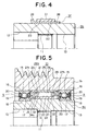
- Fig. 4 shows a fourth embodiment of the present invention.
- the large diameter portion 14 (see Figs. 1 to 3) is not provided on the outer peripheral surface of a sleeve 8b, and the outer peripheral surface of this sleeve 8b is formed in a simple cylindrical shape along the entire length in the axial direction.
- a second sleeve 37 which is formed in a substantially cylindrical shape as a whole is fitted and fixed onto the outer peripheral surface of a middle part of this sleeve 8a.
- This second sleeve 37 comprises a cylindrical portion 38 to be interference-fitted and fixed onto the outer peripheral surface of the sleeve 8b and an outward flange portion 39 which is provided on one end portion (the left end portion in Fig. 4) of this cylindrical portion 38 in the axial direction along the entire circumference thereof.
- the clutch inner race 21 is fitted and fixed onto the outer peripheral surface of a middle part of the cylindrical portion 38. Then, in case of the present embodiment, it is arranged such that the convex portion 34 (see Fig. 1) of the clutch retainer 28a is disposed between a side surface (the right side surface in Fig. 4) of the flange portion 39 and one end surface (the left end surface in Fig.
- Fig. 5 shows a fifth embodiment of the present invention.
- an eaves-shaped portion 35 which is protruding outward in the axial direction (to the left in Fig. 5) is formed at the tip end of the convex portion 34a which is formed in a protruding manner on one end portion (the left end portion in Fig. 5) of the clutch retainer 28b. Then, this eaves-shaped portion 35 is disposed between the inner end surface (the right end surface) of the inner race 18 for constituting one of the support bearings (the left one in Fig. 5) and one end surface (the left end surface in Fig. 5) of the clutch inner race 21 for constituting the roller clutch 10.
- a roller clutch is employed as the one-way clutch in the foregoing embodiments.
- a conventional one-way clutch of another type including a sprag clutch or a cam clutch
- any of such peripheral surfaces as engaging with the cam becomes a cylindrical surface. Accordingly, there is a possibility that a member for constituting the cam clutch is not fitted on any of such peripheral surfaces.
- another step surface is formed directly on a surface serving as this peripheral surface so as to be subjected to a restriction on the position of the clutch retainer in the axial direction. The same effect can be obtained not only when a pair of ball bearings are used as the paired support bearings, but also when a pair of rolling bearings or one ball bearing and one rolling bearing are used as these paired support bearings.
- the present invention is applied to a pulley for an alternator.
- the present invention is not limited to this.
- a pinion gear which can be meshed with a ring gear formed on the outer peripheral surface of a flywheel is formed on the outer peripheral surface of the outer diameter side member in a cylindrical shape.
- the rotation transmitting device incorporating a one-way clutch therein of the present invention is constituted and operated as described above, it is possible to prevent abraded powder of the clutch retainer from mixing with the grease for lubricating the one-way clutch, or to prevent deterioration of this grease in an earlier stage due to exposure of this grease to high temperature, for example. For this reason, the state of lubrication of the one-way clutch can be excellently maintained over a long term to improve the durability of the one-way clutch.
Landscapes
- Engineering & Computer Science (AREA)
- General Engineering & Computer Science (AREA)
- Mechanical Engineering (AREA)
- Pulleys (AREA)
Applications Claiming Priority (3)
| Application Number | Priority Date | Filing Date | Title |
|---|---|---|---|
| JP2000089048 | 2000-03-28 | ||
| JP2000089048A JP3652207B2 (ja) | 2000-03-28 | 2000-03-28 | 一方向クラッチ内蔵型回転伝達装置 |
| PCT/JP2001/004971 WO2002101256A1 (fr) | 2000-03-28 | 2001-06-12 | Dispositif de transmission a rotation de type encastre a embrayage a roue libre |
Publications (2)
| Publication Number | Publication Date |
|---|---|
| EP1138969A1 true EP1138969A1 (de) | 2001-10-04 |
| EP1138969B1 EP1138969B1 (de) | 2004-06-23 |
Family
ID=32449034
Family Applications (1)
| Application Number | Title | Priority Date | Filing Date |
|---|---|---|---|
| EP01302845A Expired - Lifetime EP1138969B1 (de) | 2000-03-28 | 2001-03-27 | Einrichtung zur übertragung einer Drehbewegung mit einer Einweckupplung |
Country Status (5)
| Country | Link |
|---|---|
| US (1) | US7108113B2 (de) |
| EP (1) | EP1138969B1 (de) |
| KR (1) | KR100799792B1 (de) |
| CN (1) | CN1516788A (de) |
| DE (1) | DE60103944T2 (de) |
Cited By (6)
| Publication number | Priority date | Publication date | Assignee | Title |
|---|---|---|---|---|
| US6513633B2 (en) * | 2000-03-28 | 2003-02-04 | Nsk Ltd. | Rotation transmitting device incorporating one-way clutch therein |
| DE10159439A1 (de) * | 2001-12-04 | 2003-06-26 | Ina Schaeffler Kg | Freilaufkupplung |
| GB2391049A (en) * | 2002-07-23 | 2004-01-28 | Nsk Europ Technology Co Ltd | Unit comprising a rotary bearing and a uni-directional clutch arrangement |
| EP1429052A4 (de) * | 2001-09-21 | 2005-01-19 | Nsk Ltd | Verfahren zum zusammenbau einer scheibenvorrichtung mit eingebauter rollenkupplung |
| EP2660488A1 (de) * | 2012-05-04 | 2013-11-06 | Paul Müller GmbH & Co. KG Unternehmensbeteiligungen | Klemmkörperfreilauf und Klemmkörperkäfig für diesen |
| WO2014046635A1 (en) * | 2012-09-21 | 2014-03-27 | Sari Mustafa | Locking mechanism on alternator pulley |
Families Citing this family (13)
| Publication number | Priority date | Publication date | Assignee | Title |
|---|---|---|---|---|
| JPWO2006109541A1 (ja) * | 2005-03-31 | 2008-10-30 | 新日本石油株式会社 | 一方向クラッチ用グリース組成物 |
| JP4158182B2 (ja) * | 2006-08-29 | 2008-10-01 | 三菱電機株式会社 | オーバーランニングクラッチの製造方法 |
| FR2906858B1 (fr) * | 2006-10-04 | 2008-12-05 | Skf Ab | Dispositif de poulie debrayable. |
| KR101461236B1 (ko) | 2007-04-30 | 2014-11-12 | 엘지전자 주식회사 | 무선 호를 연결 과정에서 엔티티의 인증을 수행하는 방법 |
| EP2168263B1 (de) | 2007-06-18 | 2018-04-18 | Lg Electronics Inc. | Verfahren zur übertragung von paging-informationen für effektiven rufaufbau |
| US20090308198A1 (en) * | 2008-06-17 | 2009-12-17 | Martin Jastrzembowski | Starter System with Integral Clutch Pinion for Start-Stop Engine Cranking |
| US9982726B2 (en) * | 2013-03-26 | 2018-05-29 | Nsk Ltd | One-way clutch device |
| JP2015025483A (ja) * | 2013-07-25 | 2015-02-05 | 日本精工株式会社 | 一方向クラッチ内蔵型プーリ装置 |
| JP2018173135A (ja) * | 2017-03-31 | 2018-11-08 | 株式会社ジェイテクト | クラッチ、およびそれを備えたアクチュエータ |
| CN108843771B (zh) * | 2018-07-18 | 2019-06-11 | 台州宝茨汽车零部件有限公司 | 通过轴向串动调节降低共振频率的单向器皮带轮 |
| CN110657173B (zh) * | 2019-08-21 | 2020-10-27 | 洛阳轴承研究所有限公司 | 一种内星轮超越离合器 |
| CN110671443B (zh) * | 2019-09-29 | 2023-08-08 | 厦门南超机械有限公司 | 一种中轴联接负载的离心式离合器 |
| DE102021203905B3 (de) * | 2021-04-20 | 2022-02-24 | Magna Pt B.V. & Co. Kg | Umschaltbare Freilaufeinrichtung für eine Getriebeanordnung |
Citations (5)
| Publication number | Priority date | Publication date | Assignee | Title |
|---|---|---|---|---|
| US3017002A (en) * | 1957-07-05 | 1962-01-16 | Marland One Way Clutch Co | One-way clutch |
| DE19531745A1 (de) * | 1994-08-30 | 1996-03-07 | Ntn Toyo Bearing Co Ltd | Riemenscheiben-Baueinheit |
| JPH08166027A (ja) * | 1994-12-14 | 1996-06-25 | Ntn Corp | クラッチ内蔵形プーリユニット |
| DE19626959A1 (de) * | 1996-07-04 | 1998-01-08 | Schaeffler Waelzlager Kg | Mit einem Wälzlager kombinierter Klemmrollenfreilauf |
| EP0947722A2 (de) * | 1998-01-27 | 1999-10-06 | Koyo Seiko Co., Ltd. | Freilaufkupplung |
Family Cites Families (14)
| Publication number | Priority date | Publication date | Assignee | Title |
|---|---|---|---|---|
| DE59007465D1 (de) | 1990-11-09 | 1994-11-17 | Borg Warner Automotive Gmbh | Klemmkörper-Freilauf mit einem Käfigring. |
| JPH05126169A (ja) | 1991-11-05 | 1993-05-21 | Koyo Seiko Co Ltd | 一方向クラツチ |
| JP2798567B2 (ja) | 1992-11-12 | 1998-09-17 | 光洋精工株式会社 | 一方向クラッチ |
| JPH07317807A (ja) * | 1994-03-30 | 1995-12-08 | Ntn Corp | プーリユニット |
| JP3501181B2 (ja) | 1994-11-16 | 2004-03-02 | 大豊工業株式会社 | ワンウエイクラッチのエンドベアリング |
| US5676226A (en) | 1996-05-03 | 1997-10-14 | Borg-Warner Automotive, Inc. | Sprag and roller one-way clutch assembly |
| US6170625B1 (en) * | 1997-07-01 | 2001-01-09 | Koyo Seiko Co., Ltd. | Pulley unit |
| JP2000291782A (ja) | 1999-04-07 | 2000-10-20 | Nsk Ltd | オルタネータ用一方向クラッチ内蔵型プーリ装置 |
| JP4269415B2 (ja) | 1999-07-19 | 2009-05-27 | 日本精工株式会社 | オルタネータ用ローラクラッチ内蔵型プーリ装置 |
| JP2001041314A (ja) | 1999-07-28 | 2001-02-13 | Nsk Ltd | オルタネータ用一方向クラッチ内蔵型プーリ装置 |
| JP2001090810A (ja) | 1999-09-22 | 2001-04-03 | Koyo Seiko Co Ltd | プーリユニットおよびこれに用いる一方向クラッチ |
| JP2001165201A (ja) | 1999-12-14 | 2001-06-19 | Nsk Ltd | 一方向クラッチ内蔵型回転伝達装置 |
| JP3652207B2 (ja) * | 2000-03-28 | 2005-05-25 | 日本精工株式会社 | 一方向クラッチ内蔵型回転伝達装置 |
| JP3681954B2 (ja) * | 2000-05-09 | 2005-08-10 | 三菱電機株式会社 | 一方向クラッチ内蔵型回転伝達装置 |
-
2001
- 2001-03-23 KR KR1020010015234A patent/KR100799792B1/ko not_active Expired - Fee Related
- 2001-03-27 EP EP01302845A patent/EP1138969B1/de not_active Expired - Lifetime
- 2001-03-27 DE DE60103944T patent/DE60103944T2/de not_active Expired - Lifetime
- 2001-06-12 US US10/480,382 patent/US7108113B2/en not_active Expired - Lifetime
- 2001-06-12 CN CNA018233562A patent/CN1516788A/zh active Pending
Patent Citations (5)
| Publication number | Priority date | Publication date | Assignee | Title |
|---|---|---|---|---|
| US3017002A (en) * | 1957-07-05 | 1962-01-16 | Marland One Way Clutch Co | One-way clutch |
| DE19531745A1 (de) * | 1994-08-30 | 1996-03-07 | Ntn Toyo Bearing Co Ltd | Riemenscheiben-Baueinheit |
| JPH08166027A (ja) * | 1994-12-14 | 1996-06-25 | Ntn Corp | クラッチ内蔵形プーリユニット |
| DE19626959A1 (de) * | 1996-07-04 | 1998-01-08 | Schaeffler Waelzlager Kg | Mit einem Wälzlager kombinierter Klemmrollenfreilauf |
| EP0947722A2 (de) * | 1998-01-27 | 1999-10-06 | Koyo Seiko Co., Ltd. | Freilaufkupplung |
Non-Patent Citations (1)
| Title |
|---|
| PATENT ABSTRACTS OF JAPAN vol. 1996, no. 10 31 October 1996 (1996-10-31) * |
Cited By (8)
| Publication number | Priority date | Publication date | Assignee | Title |
|---|---|---|---|---|
| US6513633B2 (en) * | 2000-03-28 | 2003-02-04 | Nsk Ltd. | Rotation transmitting device incorporating one-way clutch therein |
| EP1429052A4 (de) * | 2001-09-21 | 2005-01-19 | Nsk Ltd | Verfahren zum zusammenbau einer scheibenvorrichtung mit eingebauter rollenkupplung |
| DE10159439A1 (de) * | 2001-12-04 | 2003-06-26 | Ina Schaeffler Kg | Freilaufkupplung |
| GB2391049A (en) * | 2002-07-23 | 2004-01-28 | Nsk Europ Technology Co Ltd | Unit comprising a rotary bearing and a uni-directional clutch arrangement |
| GB2391049B (en) * | 2002-07-23 | 2006-05-31 | Nsk Europ Technology Co Ltd | A unit combining a rolling-element rotary bearing and a uni-directional clutch |
| EP2660488A1 (de) * | 2012-05-04 | 2013-11-06 | Paul Müller GmbH & Co. KG Unternehmensbeteiligungen | Klemmkörperfreilauf und Klemmkörperkäfig für diesen |
| WO2013163996A1 (de) * | 2012-05-04 | 2013-11-07 | Paul Müller GmbH & Co. KG Unternehmensbeteiligungen | Klemmkörperfreilauf und klemmkörperkäfig für diesen |
| WO2014046635A1 (en) * | 2012-09-21 | 2014-03-27 | Sari Mustafa | Locking mechanism on alternator pulley |
Also Published As
| Publication number | Publication date |
|---|---|
| US7108113B2 (en) | 2006-09-19 |
| DE60103944T2 (de) | 2005-07-07 |
| CN1516788A (zh) | 2004-07-28 |
| DE60103944D1 (de) | 2004-07-29 |
| US20040200684A1 (en) | 2004-10-14 |
| KR100799792B1 (ko) | 2008-01-31 |
| EP1138969B1 (de) | 2004-06-23 |
| KR20010093687A (ko) | 2001-10-29 |
Similar Documents
| Publication | Publication Date | Title |
|---|---|---|
| EP1138969B1 (de) | Einrichtung zur übertragung einer Drehbewegung mit einer Einweckupplung | |
| US6464057B2 (en) | Pulley with a built-in one-way clutch | |
| JPWO2003067128A1 (ja) | エンジン始動用ローラクラッチ内蔵型回転伝達装置 | |
| JP2000297860A (ja) | オルタネータ用ローラクラッチ内蔵型プーリ装置 | |
| US6513633B2 (en) | Rotation transmitting device incorporating one-way clutch therein | |
| US6749050B2 (en) | One-way clutch built-in type pulley device | |
| JP2001349413A (ja) | ローラクラッチ内蔵型プーリ装置 | |
| JP2003083426A (ja) | ローラクラッチ内蔵型プーリ装置とその組立方法 | |
| JP2000291785A (ja) | オルタネータ用一方向クラッチ内蔵型プーリ装置 | |
| JP2002349677A (ja) | ローラクラッチ及びローラクラッチ内蔵型回転伝達装置 | |
| JP2010185547A (ja) | 一方向クラッチ内蔵型プーリ装置 | |
| JP2000283267A (ja) | オルタネータ用一方向クラッチ内蔵型プーリ装置 | |
| JP2001165201A (ja) | 一方向クラッチ内蔵型回転伝達装置 | |
| JP2000328959A (ja) | オルタネータ用一方向クラッチ内蔵型プーリ装置 | |
| JP2001032911A (ja) | オルタネータ用ローラクラッチ内蔵型プーリ装置 | |
| JP2000310314A (ja) | オルタネータ用一方向クラッチ内蔵型プーリ装置及びその組立方法 | |
| JP2000240687A (ja) | ローラクラッチ及びオルタネータ用ローラクラッチ内蔵型プーリ装置 | |
| JP2003156075A (ja) | 一方向クラッチ付きプーリユニット | |
| JP4470910B2 (ja) | オルタネータ用ローラクラッチ内蔵型プーリ装置 | |
| JP2001041314A (ja) | オルタネータ用一方向クラッチ内蔵型プーリ装置 | |
| JP2000337479A (ja) | オルタネータ用ローラクラッチ内蔵型プーリ装置 | |
| JP2000240688A (ja) | ローラクラッチ | |
| JP2001099272A (ja) | 一方向クラッチ内蔵型プーリ装置 | |
| JP2003090415A (ja) | ローラクラッチ内蔵型プーリ装置 | |
| JP2005009583A (ja) | 一方向クラッチ内蔵型プーリ装置 |
Legal Events
| Date | Code | Title | Description |
|---|---|---|---|
| PUAI | Public reference made under article 153(3) epc to a published international application that has entered the european phase |
Free format text: ORIGINAL CODE: 0009012 |
|
| AK | Designated contracting states |
Kind code of ref document: A1 Designated state(s): AT BE CH CY DE DK ES FI FR GB GR IE IT LI LU MC NL PT SE TR Kind code of ref document: A1 Designated state(s): DE FR GB |
|
| AX | Request for extension of the european patent |
Free format text: AL;LT;LV;MK;RO;SI |
|
| 17P | Request for examination filed |
Effective date: 20020402 |
|
| AKX | Designation fees paid |
Free format text: DE FR GB |
|
| 17Q | First examination report despatched |
Effective date: 20020617 |
|
| GRAP | Despatch of communication of intention to grant a patent |
Free format text: ORIGINAL CODE: EPIDOSNIGR1 |
|
| GRAS | Grant fee paid |
Free format text: ORIGINAL CODE: EPIDOSNIGR3 |
|
| GRAA | (expected) grant |
Free format text: ORIGINAL CODE: 0009210 |
|
| AK | Designated contracting states |
Kind code of ref document: B1 Designated state(s): DE FR GB |
|
| REG | Reference to a national code |
Ref country code: GB Ref legal event code: FG4D |
|
| REF | Corresponds to: |
Ref document number: 60103944 Country of ref document: DE Date of ref document: 20040729 Kind code of ref document: P |
|
| ET | Fr: translation filed | ||
| PLBE | No opposition filed within time limit |
Free format text: ORIGINAL CODE: 0009261 |
|
| STAA | Information on the status of an ep patent application or granted ep patent |
Free format text: STATUS: NO OPPOSITION FILED WITHIN TIME LIMIT |
|
| 26N | No opposition filed |
Effective date: 20050324 |
|
| REG | Reference to a national code |
Ref country code: FR Ref legal event code: PLFP Year of fee payment: 16 |
|
| REG | Reference to a national code |
Ref country code: FR Ref legal event code: PLFP Year of fee payment: 17 |
|
| REG | Reference to a national code |
Ref country code: FR Ref legal event code: PLFP Year of fee payment: 18 |
|
| PGFP | Annual fee paid to national office [announced via postgrant information from national office to epo] |
Ref country code: GB Payment date: 20180321 Year of fee payment: 18 |
|
| PGFP | Annual fee paid to national office [announced via postgrant information from national office to epo] |
Ref country code: DE Payment date: 20190312 Year of fee payment: 19 |
|
| PGFP | Annual fee paid to national office [announced via postgrant information from national office to epo] |
Ref country code: FR Payment date: 20190213 Year of fee payment: 19 |
|
| GBPC | Gb: european patent ceased through non-payment of renewal fee |
Effective date: 20190327 |
|
| PG25 | Lapsed in a contracting state [announced via postgrant information from national office to epo] |
Ref country code: GB Free format text: LAPSE BECAUSE OF NON-PAYMENT OF DUE FEES Effective date: 20190327 |
|
| REG | Reference to a national code |
Ref country code: DE Ref legal event code: R119 Ref document number: 60103944 Country of ref document: DE |
|
| PG25 | Lapsed in a contracting state [announced via postgrant information from national office to epo] |
Ref country code: FR Free format text: LAPSE BECAUSE OF NON-PAYMENT OF DUE FEES Effective date: 20200331 Ref country code: DE Free format text: LAPSE BECAUSE OF NON-PAYMENT OF DUE FEES Effective date: 20201001 |