EP1138974A2 - Asymmetric wire rope isolator and method of manufacture - Google Patents
Asymmetric wire rope isolator and method of manufacture Download PDFInfo
- Publication number
- EP1138974A2 EP1138974A2 EP00127853A EP00127853A EP1138974A2 EP 1138974 A2 EP1138974 A2 EP 1138974A2 EP 00127853 A EP00127853 A EP 00127853A EP 00127853 A EP00127853 A EP 00127853A EP 1138974 A2 EP1138974 A2 EP 1138974A2
- Authority
- EP
- European Patent Office
- Prior art keywords
- wire rope
- mounting block
- hole
- holes
- lateral
- Prior art date
- Legal status (The legal status is an assumption and is not a legal conclusion. Google has not performed a legal analysis and makes no representation as to the accuracy of the status listed.)
- Withdrawn
Links
- 238000000034 method Methods 0.000 title abstract description 14
- 238000004519 manufacturing process Methods 0.000 title description 8
- 229910052782 aluminium Inorganic materials 0.000 claims 1
- XAGFODPZIPBFFR-UHFFFAOYSA-N aluminium Chemical compound [Al] XAGFODPZIPBFFR-UHFFFAOYSA-N 0.000 claims 1
- 229910052751 metal Inorganic materials 0.000 claims 1
- 239000002184 metal Substances 0.000 claims 1
- 238000002788 crimping Methods 0.000 abstract description 17
- 238000004804 winding Methods 0.000 abstract description 4
- 230000003247 decreasing effect Effects 0.000 description 2
- 230000015572 biosynthetic process Effects 0.000 description 1
- 230000006866 deterioration Effects 0.000 description 1
- 238000012986 modification Methods 0.000 description 1
- 230000004048 modification Effects 0.000 description 1
- 230000000717 retained effect Effects 0.000 description 1
- 230000035939 shock Effects 0.000 description 1
- 230000003245 working effect Effects 0.000 description 1
Images


Classifications
-
- F—MECHANICAL ENGINEERING; LIGHTING; HEATING; WEAPONS; BLASTING
- F16—ENGINEERING ELEMENTS AND UNITS; GENERAL MEASURES FOR PRODUCING AND MAINTAINING EFFECTIVE FUNCTIONING OF MACHINES OR INSTALLATIONS; THERMAL INSULATION IN GENERAL
- F16F—SPRINGS; SHOCK-ABSORBERS; MEANS FOR DAMPING VIBRATION
- F16F3/00—Spring units consisting of several springs, e.g. for obtaining a desired spring characteristic
-
- F—MECHANICAL ENGINEERING; LIGHTING; HEATING; WEAPONS; BLASTING
- F16—ENGINEERING ELEMENTS AND UNITS; GENERAL MEASURES FOR PRODUCING AND MAINTAINING EFFECTIVE FUNCTIONING OF MACHINES OR INSTALLATIONS; THERMAL INSULATION IN GENERAL
- F16F—SPRINGS; SHOCK-ABSORBERS; MEANS FOR DAMPING VIBRATION
- F16F7/00—Vibration-dampers; Shock-absorbers
- F16F7/14—Vibration-dampers; Shock-absorbers of cable support type, i.e. frictionally-engaged loop-forming cables
-
- F—MECHANICAL ENGINEERING; LIGHTING; HEATING; WEAPONS; BLASTING
- F16—ENGINEERING ELEMENTS AND UNITS; GENERAL MEASURES FOR PRODUCING AND MAINTAINING EFFECTIVE FUNCTIONING OF MACHINES OR INSTALLATIONS; THERMAL INSULATION IN GENERAL
- F16F—SPRINGS; SHOCK-ABSORBERS; MEANS FOR DAMPING VIBRATION
- F16F2236/00—Mode of stressing of basic spring or damper elements or devices incorporating such elements
- F16F2236/02—Mode of stressing of basic spring or damper elements or devices incorporating such elements the stressing resulting in flexion of the spring
-
- F—MECHANICAL ENGINEERING; LIGHTING; HEATING; WEAPONS; BLASTING
- F16—ENGINEERING ELEMENTS AND UNITS; GENERAL MEASURES FOR PRODUCING AND MAINTAINING EFFECTIVE FUNCTIONING OF MACHINES OR INSTALLATIONS; THERMAL INSULATION IN GENERAL
- F16F—SPRINGS; SHOCK-ABSORBERS; MEANS FOR DAMPING VIBRATION
- F16F2236/00—Mode of stressing of basic spring or damper elements or devices incorporating such elements
- F16F2236/02—Mode of stressing of basic spring or damper elements or devices incorporating such elements the stressing resulting in flexion of the spring
- F16F2236/027—Mode of stressing of basic spring or damper elements or devices incorporating such elements the stressing resulting in flexion of the spring of strip- or leg-type springs
-
- F—MECHANICAL ENGINEERING; LIGHTING; HEATING; WEAPONS; BLASTING
- F16—ENGINEERING ELEMENTS AND UNITS; GENERAL MEASURES FOR PRODUCING AND MAINTAINING EFFECTIVE FUNCTIONING OF MACHINES OR INSTALLATIONS; THERMAL INSULATION IN GENERAL
- F16F—SPRINGS; SHOCK-ABSORBERS; MEANS FOR DAMPING VIBRATION
- F16F2238/00—Type of springs or dampers
- F16F2238/02—Springs
-
- Y—GENERAL TAGGING OF NEW TECHNOLOGICAL DEVELOPMENTS; GENERAL TAGGING OF CROSS-SECTIONAL TECHNOLOGIES SPANNING OVER SEVERAL SECTIONS OF THE IPC; TECHNICAL SUBJECTS COVERED BY FORMER USPC CROSS-REFERENCE ART COLLECTIONS [XRACs] AND DIGESTS
- Y10—TECHNICAL SUBJECTS COVERED BY FORMER USPC
- Y10T—TECHNICAL SUBJECTS COVERED BY FORMER US CLASSIFICATION
- Y10T29/00—Metal working
- Y10T29/49—Method of mechanical manufacture
- Y10T29/49609—Spring making
- Y10T29/49615—Resilient shock or vibration absorber utility
Definitions
- This invention relates in general to vibrational energy isolators, and in particular, wire rope isolators. More specifically, but without restriction to the particular embodiment hereinafter described in accordance with the best mode of practice, this invention relates to wire rope vibration isolators employing a minimum of one asymmetric mounting block retaining a disconnected wire rope shaped into an asymmetric loop design.
- the wire rope isolator disclosed in U.S. Application No. 09/496,688 successfully solves the problems associated with traditional helical wire rope isolators.
- the disclosed isolator is capable of supporting relatively light loads. Due to the simpler design, relatively small-scale wire rope isolators can be constructed for applications having limited space. Manufacturing costs are decreased due to ability to use cheaper materials.
- a further object of the present invention is to produce a relatively small-scale isolator for use in applications with spatial limitations.
- Still another object of the present invention is to construct a wire rope isolator suited to support relatively light masses.
- An additional objective of the present invention is to develop a method of manufacturing a wire rope isolator using a singular tool and a limited number of fastening means.
- Yet a further object of the present invention is to design a wire rope isolator without a closed loop design thus reducing manufacturing error and complexity.
- Still yet another objective of the present invention is to be able to maintain tension in the wire rope throughout the crimping process to minimize dimensional and stiffness variation.
- a wire rope vibration isolator that includes a pair of mounting blocks spaced apart by a singular wire rope or a number of wire ropes manipulated into a cloverleaf pattern about the blocks.
- a first mounting block contains, at one end, a pair of closely spaced lateral holes.
- one of the pair is a blind hole used to position the end of the wire rope during assembly.
- the other hole of the pair passes axially therethrough the mounting block.
- Another through hole is located on the opposite end of the same mounting block.
- both holes of the closely spaced pair are either blind or through holes and a pair of holes, instead of one, may be situated at the opposite end of the mounting block.
- a second mounting block contains, at opposing ends of the block, two through holes, although in other embodiments of the present invention the second mounting block is although in other embodiments of the present invention the second mounting block is identical to the previously described first mounting block.
- One end of the wire rope is positioned in the blind hole of the asymmetrical block.
- the free end of wire rope is arched outward forming a U-shaped bight and then passed completely through the opposing hole of the second mounting block.
- the wire rope is arched outward again forming a second U-shaped bight between the two mounting blocks.
- the wire rope is then passed completely through the lone hole of the asymmetric mounting block.
- the wire rope is again arched outward forming a third U-shaped bight and is passed completely through the empty hole of the second mounting block.
- a fourth U-shaped bight is formed as the wire rope is arched outward from the second mounting block into the empty hole of the first mounting block.
- the wire rope is pulled completely therethrough. The tension in the rope is maintained while a crimp is formed at each lateral hole to secure the wire rope in place.
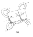
- Fig. 1 shows an assembled asymmetric wire rope isolator in accordance with the present invention.
- the asymmetric mounting block 10 which is relatively rectangular but can be any other suitable geometry, has a top and a bottom surface, opposing side surfaces and two opposing end surfaces.
- Two closely spaced lateral holes 11 and 12 are situated at the left. end of the asymmetric mounting block 10. (It should be noted that the referenced holes could be situated at the right end of the asymmetric mounting block 10).
- the lateral hole 11 closest to the left edge of the asymmetric mounting block 10 is a "blind" hole that does not pass completely through the asymmetrical mounting block.
- the purpose of the blind hole 11 is to align the end of the wire rope 30 during assembly. It is desirable that the blind hole 11 extend beyond the center of the block 10.
- a crimping force is applied at the center of the block 10 to plastically deform the mounting block into locking contact with the wire rope 30 contained therein.
- the crimping process will be described in greater detail later. If the crimp is located at the end of the wire rope 30, it is possible that wire can be pulled out of the mounting block 10 during use or significantly decrease the service life of the isolator due to fatigue of the crimp. To insure the integrity of the isolator, the blind hole 11 should extend well beyond the center of the block 10 so that the crimp is not formed at the end of the rope 30.
- the second hole 12 of the pair passes completely therethrough the asymmetric mounting block 10 from one side surface to the other side surface.
- a "lone" lateral hole 13 passes completely therethrough from one side surface of the asymmetric mounting block 10 to the other side surface of the asymmetric mounting block.
- both of the closely spaced holes are through holes or blind holes.
- the asymmetric mounting block can have two pairs of closely spaced lateral holes at opposing ends of the asymmetric block.
- the second mounting block 20 is generally rectangular in shape, but can have any other suitable geometry.
- the second mounting block 20 generally has a top and bottom surface, opposing side surfaces and two opposing end surfaces.
- Two parallel lateral holes 21 and 22, located at opposite ends of the second mounting block 20, pass completely therethrough from one side surface of the second mounting block 20 to the other side surface of the second mounting block 20.
- the second mounting block is identical to the asymmetric mounting block.
- one end of the wire rope 30 is passed completely into the "blind hole" 11 of the asymmetric mounting block 10 until it abuts the closed end of said hole.
- the free end of the wire rope 30 is arched outward and away from the asymmetric mounting block 10 to the second mounting block 20 forming a U-shaped bight 31 between the mounting blocks.
- the two mounting blocks 10 and 20 should be positioned relative to cach other so that the lateral holes 11, 12 and 13 of the asymmetrical mounting block 10 are perpendicular to the lateral holes 21 and 22 of the second mounting block 20.
- the two mounting blocks 10 and 20 should be spaced apart so that the U-shaped bights of wire rope 30 retain an elastic quality.
- the wire rope 30 is then passed completely through the lateral hole 22 on the second block 20 that is directly across from the originating blind hole 11.
- the wire rope 30 is arched away from the second mounting block 20 to the lone lateral hole 13 on the right end of the asymmetrical mounting block 10.
- Another U-shaped bight 32 is formed between the two mounting blocks 10 and 20.
- the wire rope 30 is once again arched outward forming a U-shaped wire bight 33.
- the wire rope is then completely passed through the empty lateral hole 21 of the second mounting block 20, arched outward to form a fourth U-shaped bight 34, and then passed completely through the lateral hole 12 of the asymmetrical mounting block 10 adjacent to the immediate right of the blind hole 11.
- the manipulation of the wire rope is referred to as "winding.”
- the wire rope 30 is preferably wound in this manner to create symmetry about a central axis. The symmetry enables the isolator to retain a preferred shape and provide a particular isolator stiffness.
- the tension applied to wind the wire rope 30 is maintained.
- the purpose for maintaining the tensile force in the wire rope 30 during and after winding is to minimize dimensional and stiffness variation during the crimping process.
- tension in the wire rope 30 facilitates the crimping process by better positioning the assembled wire rope isolator on the crimping apparatus.
- Each of the wire rope U-shaped bights 31, 32, 33 and 34 is secured in place by a crimp at each lateral hole 11, 12, 13, 21 and 22.
- the U-shaped bights 31, 32, 33 and 34 are thereby secured in a fixed position relative to one another. It is desirable to locate each crimp in the center of the mounting block to extend the life of the isolator. A crimp located at the edge of the lateral hole is subjected to fatigue caused by movement of the wire rope 30 during use.
- the crimps are formed by exerting a crimping force as described in U.S. Patent Application No. 09/496,688, incorporated by reference herein.
- the crimping force plastically deforms the immediately adjacent material and forms a mechanical bond between the wire rope 20 and the mounting blocks 10 and 20.
- the crimp extends into the lateral hole bonding the wire rope 30 contained therein.
- Positioning both ends in the same lateral hole requires crimping the hole at two points to secure each end of the wire in place so that it would not unwind during use.
- the two crimps could not be located in the center of the mounting block potentially decreasing the service life of the isolator due to fatigue.
- the assembled isolator is positioned on a crimping press.
- the details of the workings of the crimping press are essentially known to those of ordinary skill in the art and do not necessarily form an essential part of the present invention. Therefore, a detailed discussion is not provided, except as required. Due to the unique design of the present invention, it is possible to crimp all of the lateral holes at the same time with the same apparatus.
- the crimps 14, 15, 16, 23 and 24, as illustrated in FIG. 1, form a line down the center of each mounting block 10 and 20.
- the assembled wire rope isolator is removed from the press and is ready for use.
- the wire rope may also be retained between the mounting blocks by dowel pins as described in U.S. Patent Application No. 09/496,517 filed by Kosar et al. and incorporated by reference herein.
- Threaded retainer holes 17 and 25 are forged in the center of each mounting block 20 and 30 to affix the assembled wire rope isolator to equipment intended to be protected by the isolator.
- a chamfer or radius may be situated at the entrance and/or egress of the lateral holes 11, 12, 13, 21, and 22.
- FIG. 2 is an elevated perspective of the preferred embodiment of the present invention referenced from the top surface of the second mounting block showing in phantom the portions of the wire rope contained in the lateral holes of the described isolator.
- the four wire rope bights 31, 32, 33 and 34 are situated about the mounting blocks 10 and 20 in a cloverleaf pattern. It is preferred that the bights have substantially equal dimensions.
- a line of crimps 23 and 24 secures the wire rope 30 to the second mounting block 20.
- the wire rope 30 passes completely therethrough the lateral holes 21 and 22 of the second mounting block 20.
- the lateral holes 11, 12 and 13 of the asymmetrical mounting block 10 are illustrated as dotted lines.
- the "blind hole” does not pass completely through the asymmetric mounting block 10.
- the wire rope 30 is passed into the blind hole 11 until the end wire rope is flush with the closed portion of the hole 11.
- One end of the wire rope is passed completely through the second 12 of the pair of left-hand holes of the asymmetric mounting block 10.
- the advantages of placing the ends of the wire rope in different lateral holes have been discussed at length previously.
- the wire rope passes completely through the lone hole 13 of the asymmetric mounting block 10.
- the crimps 14, 15 and 16 securing the wire rope 30 to the asymmetrical mounting block are formed generally in a line down the center of the asymmetrical mounting block 10 over each lateral hole as shown.
- FIG. 3 depicts an elevated perspective of the present invention referenced from the outer surface of the asymmetrical mounting block 10.
- the crimps 14, 15 and 16 retaining the wire rope 30 to the asymmetrical mounting block 10 appear as they would after the crimping process according to the preferred embodiment.
- the threaded fastener 17 of the lower mounting block 30 is also shown.
Landscapes
- Engineering & Computer Science (AREA)
- General Engineering & Computer Science (AREA)
- Mechanical Engineering (AREA)
- Vibration Prevention Devices (AREA)
- Springs (AREA)
- Installation Of Indoor Wiring (AREA)
- Insulated Conductors (AREA)
- Organic Insulating Materials (AREA)
Abstract
Description
- This invention relates in general to vibrational energy isolators, and in particular, wire rope isolators. More specifically, but without restriction to the particular embodiment hereinafter described in accordance with the best mode of practice, this invention relates to wire rope vibration isolators employing a minimum of one asymmetric mounting block retaining a disconnected wire rope shaped into an asymmetric loop design.
- Excessive vibrational energy can damage and/or cause the deterioration of sophisticated machinery. In industries in which movement is inherent in daily operations, such as avionics and shipping, the need to minimize unwanted vibrational energy is imperative. These industries have come to rely heavily on sensitive electronic equipment, like navigational computers, to maintain daily operations. Constant jostling of electronic equipment can cause system failures that lead to costly downtime to replace and/or repair the damaged equipment.
- Over the years, many devices have been designed to isolate damaging vibrations and isolate unwanted kinetic energy. These devices use the unwanted kinetic energy to move simple machinery, like pistons and springs, so as to divert the energy from shock-sensitive equipment attached to the isolator. A good example of a member of this class of devices is the wire rope isolator. The most common wire rope isolators employ a helical wire cable secured between a pair of retaining members. When the isolator is in use, vibrational energy causes the wire rope coil to move in a spring-like fashion, which in turn moves the retaining members vertically toward each other. This movement diminishes the degree of vibrational energy transferred to the affixed sensitive equipment.
- The art of wire rope vibration isolators has been contributed to by a number of proposed devices detailed in U.S. Patent No. 5,549,285 issued to Collins and U.S. Patent Nos. 5,441,243 and 5,791,636 both issued to Loziuk. These patents describe vibrational energy energy isolators that consist of coiled wire ropes secured between two parallel retaining blocks. Holes drilled into the retaining blocks maintain the helical shape of the wire rope. Vibrational energy causes the wire rope coil to contract which in turn moves the entrapment blocks vertically relative to each other thus absorbing vibrational energy in the process.
- There are disadvantages with the helical design. Conventional helical wire rope isolators arc ineffective when the support load is a few pounds. In addition, helical wire rope isolators are not well suited for applications with spatial restrictions or significant weight limitations due to the need that the wire coil be of a certain length to be functional. It was therefore desirable to design a wire rope isolator that overcame the limitations associated with traditional helical wire rope isolators. U.S. Patent Application No. 09/496,688, incorporated herein by reference, discloses a wire rope vibration isolator that includes a pair of mounting blocks spaced apart by wire rope manipulated into four U-shaped bights. The bights form a cloverlcaf-type pattern between the two blocks. To maintain the bight formation, the mounting blocks are crimped into locking contact with the wire rope. When exposed to vibrational energy, the wire rope bights flex causing the mounting blocks to move toward each other expending the unwanted energy in the process.
- The wire rope isolator disclosed in U.S. Application No. 09/496,688 successfully solves the problems associated with traditional helical wire rope isolators. The disclosed isolator is capable of supporting relatively light loads. Due to the simpler design, relatively small-scale wire rope isolators can be constructed for applications having limited space. Manufacturing costs are decreased due to ability to use cheaper materials.
- It was discovered, however, that applying a tension force to the wire rope during the crimping process reduced dimensional and stiffness variation in the isolator. The design disclosed in the '688 application employs a continuous loop of wire rope having both ends located in the same hole thus prohibiting the use of a tensile force during the crimping process. It was found that locating both ends of the wire rope in the same retaining hole unnecessarily complicated the manufacturing of the isolator, thus increasing production costs. Accordingly, it is highly desirable to design a wire rope vibrational energy isolator with all of the attributes of the design disclosed in U.S. Patent Application No. 09/496,688 while maintaining tensile force in the wire rope during manufacture so that dimensional and stiffness qualities are uniform throughout the isolator.
- It is, therefore, a general object of the present invention to provide a new and improved wire rope isolator.
- It is an object of the present invention to simplify the design of wire rope isolators.
- A further object of the present invention is to produce a relatively small-scale isolator for use in applications with spatial limitations.
- Still another object of the present invention is to construct a wire rope isolator suited to support relatively light masses.
- It is yet a further object of the present invention to manufacture wire rope isolators using cost-effective materials.
- An additional objective of the present invention is to develop a method of manufacturing a wire rope isolator using a singular tool and a limited number of fastening means.
- Yet a further object of the present invention is to design a wire rope isolator without a closed loop design thus reducing manufacturing error and complexity.
- Still yet another objective of the present invention is to be able to maintain tension in the wire rope throughout the crimping process to minimize dimensional and stiffness variation.
- These and other objects are attained in accordance with the present invention of a wire rope vibration isolator that includes a pair of mounting blocks spaced apart by a singular wire rope or a number of wire ropes manipulated into a cloverleaf pattern about the blocks. According to one aspect of the present invention, a first mounting block contains, at one end, a pair of closely spaced lateral holes. In the preferred embodiment, one of the pair is a blind hole used to position the end of the wire rope during assembly. The other hole of the pair passes axially therethrough the mounting block. Another through hole is located on the opposite end of the same mounting block. In other embodiments, both holes of the closely spaced pair are either blind or through holes and a pair of holes, instead of one, may be situated at the opposite end of the mounting block.
- A second mounting block contains, at opposing ends of the block, two through holes, although in other embodiments of the present invention the second mounting block is although in other embodiments of the present invention the second mounting block is identical to the previously described first mounting block. One end of the wire rope is positioned in the blind hole of the asymmetrical block. The free end of wire rope is arched outward forming a U-shaped bight and then passed completely through the opposing hole of the second mounting block. The wire rope is arched outward again forming a second U-shaped bight between the two mounting blocks. The wire rope is then passed completely through the lone hole of the asymmetric mounting block. The wire rope is again arched outward forming a third U-shaped bight and is passed completely through the empty hole of the second mounting block. A fourth U-shaped bight is formed as the wire rope is arched outward from the second mounting block into the empty hole of the first mounting block. The wire rope is pulled completely therethrough. The tension in the rope is maintained while a crimp is formed at each lateral hole to secure the wire rope in place.
- Further objects of the present invention together with additional features contributing thereto and advantages accruing therefrom will be apparent from the following description of a preferred embodiment of the invention which is shown in the accompanying drawings with like reference numerals indicating like components throughout, wherein:
- Fig. 1 is a perspective view showing the preferred embodiment of an assembled asymmetric wire rope vibration isolator with the portions of the wire rope contained in the mounting blocks shown in phantom;
- Fig. 2 is an elevated partial perspective view of the preferred embodiment of an asymmetric wire rope vibration isolator referenced from the perspective of the outer surface of the asymmetric mounting block with those portions of the wire rope contained in the holes of the mounting blocks shown in phantom;
- Fig. 3 is an elevated perspective view of the preferred embodiment of an asymmetric wire rope vibration isolator referenced from the outer surface of the asymmetric mounting block.
-
- Fig. 1 shows an assembled asymmetric wire rope isolator in accordance with the present invention. The
asymmetric mounting block 10 which is relatively rectangular but can be any other suitable geometry, has a top and a bottom surface, opposing side surfaces and two opposing end surfaces. Two closely spacedlateral holes asymmetric mounting block 10. (It should be noted that the referenced holes could be situated at the right end of the asymmetric mounting block 10). Thelateral hole 11 closest to the left edge of theasymmetric mounting block 10 is a "blind" hole that does not pass completely through the asymmetrical mounting block. The purpose of theblind hole 11 is to align the end of thewire rope 30 during assembly. It is desirable that theblind hole 11 extend beyond the center of theblock 10. In the preferred embodiment, a crimping force is applied at the center of theblock 10 to plastically deform the mounting block into locking contact with thewire rope 30 contained therein. The crimping process will be described in greater detail later. If the crimp is located at the end of thewire rope 30, it is possible that wire can be pulled out of the mountingblock 10 during use or significantly decrease the service life of the isolator due to fatigue of the crimp. To insure the integrity of the isolator, theblind hole 11 should extend well beyond the center of theblock 10 so that the crimp is not formed at the end of therope 30. - The
second hole 12 of the pair passes completely therethrough theasymmetric mounting block 10 from one side surface to the other side surface. On the right side of theasymmetric mounting block 10, parallel to the aforementioned pair of closely spacedholes lateral hole 13 passes completely therethrough from one side surface of theasymmetric mounting block 10 to the other side surface of the asymmetric mounting block. In other embodiments of the present invention, both of the closely spaced holes are through holes or blind holes. In addition, the asymmetric mounting block can have two pairs of closely spaced lateral holes at opposing ends of the asymmetric block. - The
second mounting block 20, as illustrated, is generally rectangular in shape, but can have any other suitable geometry. Thesecond mounting block 20 generally has a top and bottom surface, opposing side surfaces and two opposing end surfaces. Two parallellateral holes second mounting block 20, pass completely therethrough from one side surface of thesecond mounting block 20 to the other side surface of thesecond mounting block 20. In another embodiment of the present invention, the second mounting block is identical to the asymmetric mounting block. - To assemble the isolator, one end of the
wire rope 30 is passed completely into the "blind hole" 11 of theasymmetric mounting block 10 until it abuts the closed end of said hole. The free end of thewire rope 30 is arched outward and away from theasymmetric mounting block 10 to thesecond mounting block 20 forming aU-shaped bight 31 between the mounting blocks. The two mountingblocks asymmetrical mounting block 10 are perpendicular to the lateral holes 21 and 22 of thesecond mounting block 20. In addition, the two mountingblocks wire rope 30 retain an elastic quality. - The
wire rope 30 is then passed completely through thelateral hole 22 on thesecond block 20 that is directly across from the originatingblind hole 11. Thewire rope 30 is arched away from thesecond mounting block 20 to the lonelateral hole 13 on the right end of theasymmetrical mounting block 10. AnotherU-shaped bight 32 is formed between the two mountingblocks asymmetrical block 20,lone hole 13, thewire rope 30 is once again arched outward forming aU-shaped wire bight 33. The wire rope is then completely passed through the emptylateral hole 21 of thesecond mounting block 20, arched outward to form a fourthU-shaped bight 34, and then passed completely through thelateral hole 12 of theasymmetrical mounting block 10 adjacent to the immediate right of theblind hole 11. The manipulation of the wire rope is referred to as "winding." Thewire rope 30 is preferably wound in this manner to create symmetry about a central axis. The symmetry enables the isolator to retain a preferred shape and provide a particular isolator stiffness. - After the
wire rope 30 has been wound about the mountingblocks wire rope 30 is maintained. The purpose for maintaining the tensile force in thewire rope 30 during and after winding is to minimize dimensional and stiffness variation during the crimping process. By keeping thewire rope 30 taut, the possibility of thewire rope 30 moving before being secured to the mounting blocks 10 and 20 is lessened. If thewire rope 30 moves, the aforementioned preferred symmetry may be lost. In addition, tension in thewire rope 30 facilitates the crimping process by better positioning the assembled wire rope isolator on the crimping apparatus. - Each of the wire rope
U-shaped bights lateral hole U-shaped bights wire rope 30 during use. - The crimps are formed by exerting a crimping force as described in U.S. Patent Application No. 09/496,688, incorporated by reference herein. The crimping force plastically deforms the immediately adjacent material and forms a mechanical bond between the
wire rope 20 and the mounting blocks 10 and 20. The crimp extends into the lateral hole bonding thewire rope 30 contained therein. By locating the ends of thewire rope 30 in differentlateral holes lateral hole - After the wire rope is wound as described, the assembled isolator is positioned on a crimping press. The details of the workings of the crimping press are essentially known to those of ordinary skill in the art and do not necessarily form an essential part of the present invention. Therefore, a detailed discussion is not provided, except as required. Due to the unique design of the present invention, it is possible to crimp all of the lateral holes at the same time with the same apparatus. The
crimps block - Threaded retainer holes 17 and 25 are forged in the center of each mounting
block - A chamfer or radius may be situated at the entrance and/or egress of the lateral holes 11, 12, 13, 21, and 22.
- FIG. 2 is an elevated perspective of the preferred embodiment of the present invention referenced from the top surface of the second mounting block showing in phantom the portions of the wire rope contained in the lateral holes of the described isolator. In the illustrated embodiment of the present invention, the four
wire rope bights blocks crimps wire rope 30 to thesecond mounting block 20. Thewire rope 30 passes completely therethrough the lateral holes 21 and 22 of thesecond mounting block 20. The lateral holes 11, 12 and 13 of theasymmetrical mounting block 10 are illustrated as dotted lines. As illustrated, the "blind hole" does not pass completely through theasymmetric mounting block 10. Thewire rope 30 is passed into theblind hole 11 until the end wire rope is flush with the closed portion of thehole 11. One end of the wire rope is passed completely through the second 12 of the pair of left-hand holes of theasymmetric mounting block 10. The advantages of placing the ends of the wire rope in different lateral holes have been discussed at length previously. The wire rope passes completely through thelone hole 13 of theasymmetric mounting block 10. Thecrimps wire rope 30 to the asymmetrical mounting block are formed generally in a line down the center of theasymmetrical mounting block 10 over each lateral hole as shown. - FIG. 3 depicts an elevated perspective of the present invention referenced from the outer surface of the
asymmetrical mounting block 10. Thecrimps wire rope 30 to theasymmetrical mounting block 10 appear as they would after the crimping process according to the preferred embodiment. The threadedfastener 17 of thelower mounting block 30 is also shown. - While this invention has been described in detail with reference to a certain preferred embodiment and preferred method for making the illustrated embodiment, it should be appreciated that the present invention is not limited to those precise embodiments. Rather, in view of the present disclosure which describes the best mode for practicing the invention, many modifications and variations would present themselves to those of skill in the art without departing from the scope and spirit of this invention, as defined in the following claims.
Claims (14)
- A wire rope vibration isolator that includes:a first and second mounting block, said first mounting block containing at one end a pair of closely spaced parallel holes one of which is a blind hole and the other a lateral hole passing axially therethrough and at the opposite end of said first mounting block a lateral hole passing axially therethrough;a second mounting block having at one end a hole passing axially therethrough and at the opposing end a second hole passing axially therethrough;wire rope passing into and through said holes to space the blocks apart;at least one securing means located at each hole to secure the wire rope into locking contact with the blocks.
- The wire rope vibration isolator of claim 1, wherein one end of said wire rope is located in said blind hole of the first mounting block and the opposite end of said wire rope is passed completely through the lateral hole adjacent to said blind hole.
- The wire rope vibration isolator of claim 1, wherein a plurality of outwardly extending wire rope bights having spring-like qualities are formed between said blocks.
- The wire rope vibration isolator of claim 1, wherein the lateral holes of the first block are perpendicular to the lateral holes of said second block.
- The wire rope vibration isolator of claim 1, wherein said holes are substantially cylindrical having a diameter slightly greater than said wire rope.
- The wire rope vibration isolator of claim 1, wherein said securing means consists of a crimp formed at each lateral hole so as to secure said wire rope into locking contact with said mounting blocks.
- The wire rope vibration isolator of claim 6, wherein said crimp is located at the center of each lateral hole.
- The wire rope vibration isolator of claim 1, wherein said securing means is a dowel pin driven through said mounting block into each lateral hole so as to stake the wire rope contained therein into locking contact with the mounting block.
- The wire rope vibration isolator of claim 1, wherein both of the closely spaced parallel holes of the first mounting block are blind holes.
- The wire rope vibration isolator of claim 1, wherein both of the closely spaced parallel holes of the first mounting block are through holes.
- The wire rope vibration isolator of claim 1, wherein each lateral hole contains a chamfer at the exit and entrance of the hole.
- The wire rope vibration isolator of claim 1, wherein each lateral hole contains a radius at entrance and exit of the hole.
- The wire rope isolator of claim 1, wherein said mounting blocks are composed of metal.
- The wire rope isolator of claim 1, wherein said mounting blocks are composed of aluminum.
Priority Applications (1)
| Application Number | Priority Date | Filing Date | Title |
|---|---|---|---|
| EP06000698A EP1666760B1 (en) | 2000-03-29 | 2000-12-20 | Asymmetric wire rope isolator |
Applications Claiming Priority (2)
| Application Number | Priority Date | Filing Date | Title |
|---|---|---|---|
| US09/537,918 US6290217B1 (en) | 2000-03-29 | 2000-03-29 | Asymmetric wire rope isolator |
| US537918 | 2000-03-29 |
Related Child Applications (1)
| Application Number | Title | Priority Date | Filing Date |
|---|---|---|---|
| EP06000698A Division EP1666760B1 (en) | 2000-03-29 | 2000-12-20 | Asymmetric wire rope isolator |
Publications (2)
| Publication Number | Publication Date |
|---|---|
| EP1138974A2 true EP1138974A2 (en) | 2001-10-04 |
| EP1138974A3 EP1138974A3 (en) | 2002-03-06 |
Family
ID=24144656
Family Applications (2)
| Application Number | Title | Priority Date | Filing Date |
|---|---|---|---|
| EP06000698A Expired - Lifetime EP1666760B1 (en) | 2000-03-29 | 2000-12-20 | Asymmetric wire rope isolator |
| EP00127853A Withdrawn EP1138974A3 (en) | 2000-03-29 | 2000-12-20 | Asymmetric wire rope isolator and method of manufacture |
Family Applications Before (1)
| Application Number | Title | Priority Date | Filing Date |
|---|---|---|---|
| EP06000698A Expired - Lifetime EP1666760B1 (en) | 2000-03-29 | 2000-12-20 | Asymmetric wire rope isolator |
Country Status (7)
| Country | Link |
|---|---|
| US (1) | US6290217B1 (en) |
| EP (2) | EP1666760B1 (en) |
| JP (1) | JP4492906B2 (en) |
| KR (1) | KR100741594B1 (en) |
| AT (1) | ATE394610T1 (en) |
| DE (1) | DE60038832D1 (en) |
| ES (1) | ES2307236T3 (en) |
Cited By (7)
| Publication number | Priority date | Publication date | Assignee | Title |
|---|---|---|---|---|
| EP1519073A1 (en) * | 2003-09-25 | 2005-03-30 | Sebert Schwingungstechnik GmbH | Damping arrangement comprising a cable loop arrangement as a damper |
| EP1619364A1 (en) | 2004-07-20 | 2006-01-25 | Scambia Industrial Developments AG | Vibration isolator |
| EP2392836A1 (en) * | 2010-06-02 | 2011-12-07 | Thales Nederland B.V. | A device for isolating an object from external motions |
| EP2639476A1 (en) * | 2012-03-15 | 2013-09-18 | ThyssenKrupp Marine Systems GmbH | Shock absorber for storing an object in or on a vehicle |
| US9255399B2 (en) | 2013-12-06 | 2016-02-09 | Itt Manufacturing Enterprises Llc | Seismic isolation assembly |
| US10539204B2 (en) | 2014-09-24 | 2020-01-21 | Itt Manufacturing Enterprises Llc | Damping and support device for electrical equipments |
| US11572929B2 (en) | 2020-04-16 | 2023-02-07 | Raytheon Company | Vibration isolator and method of assembly using flex circuits |
Families Citing this family (26)
| Publication number | Priority date | Publication date | Assignee | Title |
|---|---|---|---|---|
| JP3967274B2 (en) * | 2003-02-27 | 2007-08-29 | 株式会社ミツトヨ | measuring device |
| RU2305809C2 (en) * | 2003-10-13 | 2007-09-10 | Общество с ограниченной ответственностью "Научно-производственная фирма "АНКОМ" | Rope shock absorber and method of its making |
| US7325792B2 (en) * | 2005-03-11 | 2008-02-05 | Enidine, Inc. | Multi-axial base isolation system |
| RU2351816C2 (en) * | 2007-03-05 | 2009-04-10 | Государственное образовательное учреждение высшего профессионального образования Военно-морская академия имени Адмирала Флота Советского Союза Н.Г. КУЗНЕЦОВА | Vibroinsulator |
| RU2336448C1 (en) * | 2007-03-05 | 2008-10-20 | Государственное образовательное учреждение высшего профессионального образования Военно-морская академия имени Адмирала Флота Советского Союза Н.Г. КУЗНЕЦОВА | Antivibration support |
| RU2346195C2 (en) * | 2007-03-19 | 2009-02-10 | Государственное образовательное учреждение высшего профессионального образования Военно-морская академия имени Адмирала Флота Советского Союза Н.Г. КУЗНЕЦОВА | Vibration isolator |
| RU2341704C1 (en) * | 2007-05-23 | 2008-12-20 | Государственное образовательное учреждение высшего профессионального образования "Санкт-Петербургский государственный морской технический университет" | Antivibration device |
| WO2010076786A2 (en) | 2008-12-29 | 2010-07-08 | Otic Pharma Ltd. | Multiple-metered self-cleaning dispenser |
| GB2478260B (en) | 2009-01-21 | 2014-02-26 | Rafael Advanced Defense Sys | Damping suspension with an up-lift capability for an add-on armor system |
| KR20100111334A (en) * | 2009-04-07 | 2010-10-15 | 하동석 | Wire shock mount with motion guide and article having same |
| RU2403466C1 (en) * | 2009-05-28 | 2010-11-10 | Государственное образовательное учреждение высшего профессионального образования "Санкт-Петербургский государственный морской технический университет" | Vibration isolating device |
| US8657250B2 (en) * | 2010-03-19 | 2014-02-25 | Winegard Company | Mount for a mobile satellite antenna system with vibration and shock isolation |
| DE102012206015B4 (en) | 2012-04-12 | 2015-02-12 | Sebert Schwingungstechnik Gmbh | Vibration isolator and method for its production |
| US9370776B2 (en) * | 2013-04-29 | 2016-06-21 | Vermeer Manufacturing Company | Mounting block for attaching a reducing element to a rotary drum |
| US10005506B2 (en) | 2015-02-27 | 2018-06-26 | Great Lakes Sound & Vibration, Inc. | Suspension arrangements for vehicles |
| US9788446B1 (en) * | 2015-03-27 | 2017-10-10 | Paul H. Townsend | Mobile vibration isolation device |
| US11326661B2 (en) | 2016-11-22 | 2022-05-10 | Textron Innovations Inc. | Damper |
| US10232936B2 (en) | 2016-11-22 | 2019-03-19 | Bell Helicopter Textron Inc. | Damper |
| US10570984B1 (en) | 2017-06-28 | 2020-02-25 | United Launch Alliance, L.L.C. | Asymmetrically-shaped isolator |
| FR3075908B1 (en) * | 2017-12-27 | 2020-09-25 | Airbus Operations Sas | DAMPING SYSTEM INCLUDING A PRIMARY DAMPER AND A SECONDARY DAMPER DEVICE FOR DIFFERENT STIFFNESS, ASSOCIATED STRUCTURE AND AIRCRAFT |
| US10619967B2 (en) * | 2018-01-30 | 2020-04-14 | Daniel N. Kelly | Energy absorber and method for shooting equipment |
| RU184019U1 (en) * | 2018-06-19 | 2018-10-11 | Общество с ограниченной ответственностью "Технические системы-сервис, качество и надежность" | DEVICE FOR STABILIZING VIBRATION INSULATOR BRANCHES |
| EP3705744B1 (en) | 2019-03-05 | 2021-10-20 | Bell Helicopter Textron Inc. | Damper |
| NL2026755B1 (en) | 2020-10-23 | 2022-06-17 | Turtle B V | Support for a work of art |
| DE102022200733A1 (en) * | 2022-01-24 | 2023-07-27 | Karl Sebert | damping arrangement |
| DE102024211764A1 (en) * | 2024-12-10 | 2026-06-11 | Stellantis Auto Sas | Vibration damper |
Citations (4)
| Publication number | Priority date | Publication date | Assignee | Title |
|---|---|---|---|---|
| US3476851A (en) * | 1964-12-21 | 1969-11-04 | Carlo Camossi | Method for making vibration dampening and shock absorbing support |
| US5441243A (en) | 1992-07-16 | 1995-08-15 | Vectra Technologies, Inc. | Wire cable isolator and energy absorbing restraint |
| US5549285A (en) | 1995-04-21 | 1996-08-27 | Enidine, Inc. | Wire rope isolator with crimp bar and method for making same |
| US5791636A (en) | 1992-07-16 | 1998-08-11 | Loziuk; Larry | Compact profile wire cable isolator and energy absorbing restraint |
Family Cites Families (24)
| Publication number | Priority date | Publication date | Assignee | Title |
|---|---|---|---|---|
| US3044759A (en) * | 1959-11-27 | 1962-07-17 | Kerley Engineering Inc | Cable type vibration isolator with captivating elements |
| US3360225A (en) * | 1963-04-11 | 1967-12-26 | Camossi Carlo | Process for manufacturing isolators of shock absorbers based on the principle of damping vibrations and/or shocks by means of multistrand cables |
| US3596865A (en) * | 1967-05-26 | 1971-08-03 | Carlo Camossi | Metal cable absorber mounting system |
| JPS5135867A (en) * | 1974-09-20 | 1976-03-26 | Chuo Hatsujo Kk | BOSHINKAN SHOSOCHI |
| US4190227A (en) * | 1976-07-22 | 1980-02-26 | Aeroflex Laboratories, Inc. | Vibration isolator and method for manufacturing same |
| IT1121445B (en) * | 1979-06-20 | 1986-04-02 | Camossi Carlo | DEVICE AND PROCEDURE FOR THE MANUFACTURE OF ANTIVIBRATION AND SHOCK ABSORBING SUPPORTS AT LEAST ONE METAL CABLE ARRANGED IN A PROPELLER AND SUPPORT SO OBTAINED |
| FR2601739B1 (en) * | 1986-07-15 | 1990-08-10 | Commerce Internal Echanges Tec | ANTI-SHOCK ANTI-VIBRATION DEVICE AND METHOD FOR MANUFACTURING SUCH A DEVICE |
| US4991827A (en) * | 1986-11-10 | 1991-02-12 | Tayco Developments, Inc. | Springs formed of rope pressure-saturated or impregnated with binder |
| US4783038A (en) * | 1987-07-07 | 1988-11-08 | Aeroflex International Incorporated | Isolator apparatus |
| FR2636111B1 (en) * | 1988-09-05 | 1990-11-16 | Vibrachoc Sa | SHOCK AND VIBRATION DAMPING DEVICE |
| IT1229805B (en) * | 1988-11-10 | 1991-09-13 | Pirelli Cavi Spa | DEVICE FOR MOUNTING SLEEVES TO MAKE ELECTRIC CABLE JUNCTIONS |
| JPH02272160A (en) * | 1989-04-12 | 1990-11-06 | Toshiba Corp | Shock absorber |
| US5169110A (en) * | 1991-07-18 | 1992-12-08 | Aeroflex International Incorporated | Force-damping energy-removing isolator |
| US5240232A (en) * | 1991-12-16 | 1993-08-31 | Abb Impell Corporation | Pipe restraint |
| US5277394A (en) * | 1992-11-02 | 1994-01-11 | Arlo Slemmer | Coaxial isolator device |
| FR2702020B1 (en) * | 1993-02-22 | 1995-05-24 | Socitec | Anti-vibration / anti-shock device and method of manufacturing such a device. |
| FR2738888B1 (en) * | 1995-09-20 | 1998-12-04 | Socitec | ANTI-VIBRATION/ANTI-SHOCK DEVICE OF THE KIND COMPRISING A BEARING ELEMENT AND A CARRY ELEMENT UNITED BY CABLE SEGMENTS AND STABILIZING BLADES |
| DE29610412U1 (en) * | 1996-06-13 | 1996-08-14 | Siemens AG, 80333 München | Wire rope vibration damper |
| US5950970A (en) * | 1996-12-24 | 1999-09-14 | United Technologies Corporation | Cable clamp damper |
| JP3589553B2 (en) * | 1997-09-12 | 2004-11-17 | 辰治 石丸 | Damping unit and damper |
| US6002588A (en) * | 1997-12-04 | 1999-12-14 | Lockheed Martin Corporation | Thermally conductive vibration isolators |
| JP3595439B2 (en) * | 1997-12-17 | 2004-12-02 | 核燃料サイクル開発機構 | Compression / tensile load type lead damper |
| US6244579B1 (en) | 2000-02-02 | 2001-06-12 | Enidine, Incorporated | Light press manufactured (LPM) wire rope isolator and method of manufacture |
| US6406011B1 (en) * | 2000-02-02 | 2002-06-18 | Enidine Incorporated | Wire rope isolator with pinned bar and method for making same |
-
2000
- 2000-03-29 US US09/537,918 patent/US6290217B1/en not_active Expired - Lifetime
- 2000-10-10 KR KR1020000059403A patent/KR100741594B1/en not_active Expired - Fee Related
- 2000-12-20 DE DE60038832T patent/DE60038832D1/en not_active Expired - Lifetime
- 2000-12-20 EP EP06000698A patent/EP1666760B1/en not_active Expired - Lifetime
- 2000-12-20 ES ES06000698T patent/ES2307236T3/en not_active Expired - Lifetime
- 2000-12-20 EP EP00127853A patent/EP1138974A3/en not_active Withdrawn
- 2000-12-20 AT AT06000698T patent/ATE394610T1/en not_active IP Right Cessation
-
2001
- 2001-03-29 JP JP2001095345A patent/JP4492906B2/en not_active Expired - Lifetime
Patent Citations (4)
| Publication number | Priority date | Publication date | Assignee | Title |
|---|---|---|---|---|
| US3476851A (en) * | 1964-12-21 | 1969-11-04 | Carlo Camossi | Method for making vibration dampening and shock absorbing support |
| US5441243A (en) | 1992-07-16 | 1995-08-15 | Vectra Technologies, Inc. | Wire cable isolator and energy absorbing restraint |
| US5791636A (en) | 1992-07-16 | 1998-08-11 | Loziuk; Larry | Compact profile wire cable isolator and energy absorbing restraint |
| US5549285A (en) | 1995-04-21 | 1996-08-27 | Enidine, Inc. | Wire rope isolator with crimp bar and method for making same |
Cited By (13)
| Publication number | Priority date | Publication date | Assignee | Title |
|---|---|---|---|---|
| US7303185B2 (en) | 2003-09-25 | 2007-12-04 | Sebert Schwingungstechnik Gmbh | Damping arrangement with a cable loop arrangement serving as a damping member |
| EP1519073A1 (en) * | 2003-09-25 | 2005-03-30 | Sebert Schwingungstechnik GmbH | Damping arrangement comprising a cable loop arrangement as a damper |
| EP1619364A1 (en) | 2004-07-20 | 2006-01-25 | Scambia Industrial Developments AG | Vibration isolator |
| US7631855B2 (en) | 2004-07-20 | 2009-12-15 | Scambia Industrial Developments Ag | Vibration isolator |
| US9341225B2 (en) | 2010-02-06 | 2016-05-17 | Thales Nederland B.V. | Device for isolating an object from external motions |
| US9523405B2 (en) | 2010-06-02 | 2016-12-20 | Thales Nederland B.V. | Device for isolating an object from external motions |
| WO2011151254A1 (en) * | 2010-06-02 | 2011-12-08 | Thales Nederland B.V. | A device for isolating an object from external motions |
| EP2392836A1 (en) * | 2010-06-02 | 2011-12-07 | Thales Nederland B.V. | A device for isolating an object from external motions |
| EP2639476A1 (en) * | 2012-03-15 | 2013-09-18 | ThyssenKrupp Marine Systems GmbH | Shock absorber for storing an object in or on a vehicle |
| US9255399B2 (en) | 2013-12-06 | 2016-02-09 | Itt Manufacturing Enterprises Llc | Seismic isolation assembly |
| US9809975B2 (en) | 2013-12-06 | 2017-11-07 | Itt Manufacturing Enterprises Llc | Seismic isolation assembly |
| US10539204B2 (en) | 2014-09-24 | 2020-01-21 | Itt Manufacturing Enterprises Llc | Damping and support device for electrical equipments |
| US11572929B2 (en) | 2020-04-16 | 2023-02-07 | Raytheon Company | Vibration isolator and method of assembly using flex circuits |
Also Published As
| Publication number | Publication date |
|---|---|
| KR100741594B1 (en) | 2007-07-20 |
| KR20010093625A (en) | 2001-10-29 |
| EP1666760A2 (en) | 2006-06-07 |
| JP2001317590A (en) | 2001-11-16 |
| EP1666760B1 (en) | 2008-05-07 |
| ATE394610T1 (en) | 2008-05-15 |
| ES2307236T3 (en) | 2008-11-16 |
| DE60038832D1 (en) | 2008-06-19 |
| US6290217B1 (en) | 2001-09-18 |
| EP1666760A3 (en) | 2006-08-02 |
| JP4492906B2 (en) | 2010-06-30 |
| EP1138974A3 (en) | 2002-03-06 |
Similar Documents
| Publication | Publication Date | Title |
|---|---|---|
| US6290217B1 (en) | Asymmetric wire rope isolator | |
| EP1122458A1 (en) | Wire rope isolator with pinned bar and method for making same | |
| EP1132646B1 (en) | Light press manufactured (LPM) wire rope isolator and method of manufacture | |
| JP3848366B2 (en) | Locking tool with snake-shaped gripping member | |
| JP4167492B2 (en) | Terminal assembly for elevator load support | |
| WO1996033355B1 (en) | Wire rope isolator with crimp bar and method for making same | |
| US10138970B2 (en) | Coil spring | |
| JP6496530B2 (en) | Turbo generator stator core suspension | |
| WO1996033355A3 (en) | Wire rope isolator with crimp bar and method for making same | |
| JPH07223774A (en) | Storage reel for cords, etc. | |
| EP2742254B1 (en) | Hysteretic tuned-mass damper device (tmd) for passive control of mechanical vibrations | |
| US7684670B2 (en) | Wire accommodation apparatus | |
| US5037357A (en) | Belt or chain tensioner for power transmitting system | |
| US6299150B1 (en) | Composite spring mount shock absorber | |
| US8613431B1 (en) | Vibration isolator with improved symmetry | |
| JPH10311357A (en) | Spring assembly | |
| GB2317432A (en) | Coil spring | |
| JP4302068B2 (en) | Anti-vibration device with weight drop prevention function | |
| KR101362927B1 (en) | Wire rope isolator and vibration isolation system using the same | |
| TW541281B (en) | Self-locking warp termination for tension member | |
| DE19958928A1 (en) | Vibration damping device has two spaced apart baseplates between which are installed paired coil springs in which are fitted cylindrically constructed elastomer guide elements | |
| US6260833B1 (en) | Fail safe coil spring including mounting mechanism | |
| KR20210056640A (en) | Bolt-assembled termination device | |
| US5620170A (en) | Coil spring supporting device | |
| JP3544756B2 (en) | Elasto-plastic damper device |
Legal Events
| Date | Code | Title | Description |
|---|---|---|---|
| PUAI | Public reference made under article 153(3) epc to a published international application that has entered the european phase |
Free format text: ORIGINAL CODE: 0009012 |
|
| AK | Designated contracting states |
Kind code of ref document: A2 Designated state(s): AT BE CH CY DE DK ES FI FR GB GR IE IT LI LU MC NL PT SE TR |
|
| AX | Request for extension of the european patent |
Free format text: AL;LT;LV;MK;RO;SI |
|
| PUAL | Search report despatched |
Free format text: ORIGINAL CODE: 0009013 |
|
| AK | Designated contracting states |
Kind code of ref document: A3 Designated state(s): AT BE CH CY DE DK ES FI FR GB GR IE IT LI LU MC NL PT SE TR |
|
| AX | Request for extension of the european patent |
Free format text: AL;LT;LV;MK;RO;SI |
|
| 17P | Request for examination filed |
Effective date: 20020816 |
|
| AKX | Designation fees paid |
Free format text: AT BE CH CY DE DK ES FI FR GB GR IE IT LI LU MC NL PT SE TR |
|
| 17Q | First examination report despatched |
Effective date: 20040816 |
|
| RTI1 | Title (correction) |
Free format text: ASYMMETRIC WIRE ROPE ISOLATOR |
|
| GRAP | Despatch of communication of intention to grant a patent |
Free format text: ORIGINAL CODE: EPIDOSNIGR1 |
|
| GRAS | Grant fee paid |
Free format text: ORIGINAL CODE: EPIDOSNIGR3 |
|
| STAA | Information on the status of an ep patent application or granted ep patent |
Free format text: STATUS: THE APPLICATION IS DEEMED TO BE WITHDRAWN |
|
| 18D | Application deemed to be withdrawn |
Effective date: 20060621 |