EP1138974A2 - Asymmetrischer Drahtseilisolator und Herstellungsmethode - Google Patents
Asymmetrischer Drahtseilisolator und Herstellungsmethode Download PDFInfo
- Publication number
- EP1138974A2 EP1138974A2 EP00127853A EP00127853A EP1138974A2 EP 1138974 A2 EP1138974 A2 EP 1138974A2 EP 00127853 A EP00127853 A EP 00127853A EP 00127853 A EP00127853 A EP 00127853A EP 1138974 A2 EP1138974 A2 EP 1138974A2
- Authority
- EP
- European Patent Office
- Prior art keywords
- wire rope
- mounting block
- hole
- holes
- lateral
- Prior art date
- Legal status (The legal status is an assumption and is not a legal conclusion. Google has not performed a legal analysis and makes no representation as to the accuracy of the status listed.)
- Withdrawn
Links
- 238000000034 method Methods 0.000 title abstract description 14
- 238000004519 manufacturing process Methods 0.000 title description 8
- 229910052782 aluminium Inorganic materials 0.000 claims 1
- XAGFODPZIPBFFR-UHFFFAOYSA-N aluminium Chemical compound [Al] XAGFODPZIPBFFR-UHFFFAOYSA-N 0.000 claims 1
- 229910052751 metal Inorganic materials 0.000 claims 1
- 239000002184 metal Substances 0.000 claims 1
- 238000002788 crimping Methods 0.000 abstract description 17
- 238000004804 winding Methods 0.000 abstract description 4
- 230000003247 decreasing effect Effects 0.000 description 2
- 230000015572 biosynthetic process Effects 0.000 description 1
- 230000006866 deterioration Effects 0.000 description 1
- 238000012986 modification Methods 0.000 description 1
- 230000004048 modification Effects 0.000 description 1
- 230000000717 retained effect Effects 0.000 description 1
- 230000035939 shock Effects 0.000 description 1
- 230000003245 working effect Effects 0.000 description 1
Images


Classifications
-
- F—MECHANICAL ENGINEERING; LIGHTING; HEATING; WEAPONS; BLASTING
- F16—ENGINEERING ELEMENTS AND UNITS; GENERAL MEASURES FOR PRODUCING AND MAINTAINING EFFECTIVE FUNCTIONING OF MACHINES OR INSTALLATIONS; THERMAL INSULATION IN GENERAL
- F16F—SPRINGS; SHOCK-ABSORBERS; MEANS FOR DAMPING VIBRATION
- F16F3/00—Spring units consisting of several springs, e.g. for obtaining a desired spring characteristic
-
- F—MECHANICAL ENGINEERING; LIGHTING; HEATING; WEAPONS; BLASTING
- F16—ENGINEERING ELEMENTS AND UNITS; GENERAL MEASURES FOR PRODUCING AND MAINTAINING EFFECTIVE FUNCTIONING OF MACHINES OR INSTALLATIONS; THERMAL INSULATION IN GENERAL
- F16F—SPRINGS; SHOCK-ABSORBERS; MEANS FOR DAMPING VIBRATION
- F16F7/00—Vibration-dampers; Shock-absorbers
- F16F7/14—Vibration-dampers; Shock-absorbers of cable support type, i.e. frictionally-engaged loop-forming cables
-
- F—MECHANICAL ENGINEERING; LIGHTING; HEATING; WEAPONS; BLASTING
- F16—ENGINEERING ELEMENTS AND UNITS; GENERAL MEASURES FOR PRODUCING AND MAINTAINING EFFECTIVE FUNCTIONING OF MACHINES OR INSTALLATIONS; THERMAL INSULATION IN GENERAL
- F16F—SPRINGS; SHOCK-ABSORBERS; MEANS FOR DAMPING VIBRATION
- F16F2236/00—Mode of stressing of basic spring or damper elements or devices incorporating such elements
- F16F2236/02—Mode of stressing of basic spring or damper elements or devices incorporating such elements the stressing resulting in flexion of the spring
-
- F—MECHANICAL ENGINEERING; LIGHTING; HEATING; WEAPONS; BLASTING
- F16—ENGINEERING ELEMENTS AND UNITS; GENERAL MEASURES FOR PRODUCING AND MAINTAINING EFFECTIVE FUNCTIONING OF MACHINES OR INSTALLATIONS; THERMAL INSULATION IN GENERAL
- F16F—SPRINGS; SHOCK-ABSORBERS; MEANS FOR DAMPING VIBRATION
- F16F2236/00—Mode of stressing of basic spring or damper elements or devices incorporating such elements
- F16F2236/02—Mode of stressing of basic spring or damper elements or devices incorporating such elements the stressing resulting in flexion of the spring
- F16F2236/027—Mode of stressing of basic spring or damper elements or devices incorporating such elements the stressing resulting in flexion of the spring of strip- or leg-type springs
-
- F—MECHANICAL ENGINEERING; LIGHTING; HEATING; WEAPONS; BLASTING
- F16—ENGINEERING ELEMENTS AND UNITS; GENERAL MEASURES FOR PRODUCING AND MAINTAINING EFFECTIVE FUNCTIONING OF MACHINES OR INSTALLATIONS; THERMAL INSULATION IN GENERAL
- F16F—SPRINGS; SHOCK-ABSORBERS; MEANS FOR DAMPING VIBRATION
- F16F2238/00—Type of springs or dampers
- F16F2238/02—Springs
-
- Y—GENERAL TAGGING OF NEW TECHNOLOGICAL DEVELOPMENTS; GENERAL TAGGING OF CROSS-SECTIONAL TECHNOLOGIES SPANNING OVER SEVERAL SECTIONS OF THE IPC; TECHNICAL SUBJECTS COVERED BY FORMER USPC CROSS-REFERENCE ART COLLECTIONS [XRACs] AND DIGESTS
- Y10—TECHNICAL SUBJECTS COVERED BY FORMER USPC
- Y10T—TECHNICAL SUBJECTS COVERED BY FORMER US CLASSIFICATION
- Y10T29/00—Metal working
- Y10T29/49—Method of mechanical manufacture
- Y10T29/49609—Spring making
- Y10T29/49615—Resilient shock or vibration absorber utility
Definitions
- This invention relates in general to vibrational energy isolators, and in particular, wire rope isolators. More specifically, but without restriction to the particular embodiment hereinafter described in accordance with the best mode of practice, this invention relates to wire rope vibration isolators employing a minimum of one asymmetric mounting block retaining a disconnected wire rope shaped into an asymmetric loop design.
- the wire rope isolator disclosed in U.S. Application No. 09/496,688 successfully solves the problems associated with traditional helical wire rope isolators.
- the disclosed isolator is capable of supporting relatively light loads. Due to the simpler design, relatively small-scale wire rope isolators can be constructed for applications having limited space. Manufacturing costs are decreased due to ability to use cheaper materials.
- a further object of the present invention is to produce a relatively small-scale isolator for use in applications with spatial limitations.
- Still another object of the present invention is to construct a wire rope isolator suited to support relatively light masses.
- An additional objective of the present invention is to develop a method of manufacturing a wire rope isolator using a singular tool and a limited number of fastening means.
- Yet a further object of the present invention is to design a wire rope isolator without a closed loop design thus reducing manufacturing error and complexity.
- Still yet another objective of the present invention is to be able to maintain tension in the wire rope throughout the crimping process to minimize dimensional and stiffness variation.
- a wire rope vibration isolator that includes a pair of mounting blocks spaced apart by a singular wire rope or a number of wire ropes manipulated into a cloverleaf pattern about the blocks.
- a first mounting block contains, at one end, a pair of closely spaced lateral holes.
- one of the pair is a blind hole used to position the end of the wire rope during assembly.
- the other hole of the pair passes axially therethrough the mounting block.
- Another through hole is located on the opposite end of the same mounting block.
- both holes of the closely spaced pair are either blind or through holes and a pair of holes, instead of one, may be situated at the opposite end of the mounting block.
- a second mounting block contains, at opposing ends of the block, two through holes, although in other embodiments of the present invention the second mounting block is although in other embodiments of the present invention the second mounting block is identical to the previously described first mounting block.
- One end of the wire rope is positioned in the blind hole of the asymmetrical block.
- the free end of wire rope is arched outward forming a U-shaped bight and then passed completely through the opposing hole of the second mounting block.
- the wire rope is arched outward again forming a second U-shaped bight between the two mounting blocks.
- the wire rope is then passed completely through the lone hole of the asymmetric mounting block.
- the wire rope is again arched outward forming a third U-shaped bight and is passed completely through the empty hole of the second mounting block.
- a fourth U-shaped bight is formed as the wire rope is arched outward from the second mounting block into the empty hole of the first mounting block.
- the wire rope is pulled completely therethrough. The tension in the rope is maintained while a crimp is formed at each lateral hole to secure the wire rope in place.
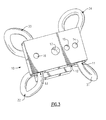
- Fig. 1 shows an assembled asymmetric wire rope isolator in accordance with the present invention.
- the asymmetric mounting block 10 which is relatively rectangular but can be any other suitable geometry, has a top and a bottom surface, opposing side surfaces and two opposing end surfaces.
- Two closely spaced lateral holes 11 and 12 are situated at the left. end of the asymmetric mounting block 10. (It should be noted that the referenced holes could be situated at the right end of the asymmetric mounting block 10).
- the lateral hole 11 closest to the left edge of the asymmetric mounting block 10 is a "blind" hole that does not pass completely through the asymmetrical mounting block.
- the purpose of the blind hole 11 is to align the end of the wire rope 30 during assembly. It is desirable that the blind hole 11 extend beyond the center of the block 10.
- a crimping force is applied at the center of the block 10 to plastically deform the mounting block into locking contact with the wire rope 30 contained therein.
- the crimping process will be described in greater detail later. If the crimp is located at the end of the wire rope 30, it is possible that wire can be pulled out of the mounting block 10 during use or significantly decrease the service life of the isolator due to fatigue of the crimp. To insure the integrity of the isolator, the blind hole 11 should extend well beyond the center of the block 10 so that the crimp is not formed at the end of the rope 30.
- the second hole 12 of the pair passes completely therethrough the asymmetric mounting block 10 from one side surface to the other side surface.
- a "lone" lateral hole 13 passes completely therethrough from one side surface of the asymmetric mounting block 10 to the other side surface of the asymmetric mounting block.
- both of the closely spaced holes are through holes or blind holes.
- the asymmetric mounting block can have two pairs of closely spaced lateral holes at opposing ends of the asymmetric block.
- the second mounting block 20 is generally rectangular in shape, but can have any other suitable geometry.
- the second mounting block 20 generally has a top and bottom surface, opposing side surfaces and two opposing end surfaces.
- Two parallel lateral holes 21 and 22, located at opposite ends of the second mounting block 20, pass completely therethrough from one side surface of the second mounting block 20 to the other side surface of the second mounting block 20.
- the second mounting block is identical to the asymmetric mounting block.
- one end of the wire rope 30 is passed completely into the "blind hole" 11 of the asymmetric mounting block 10 until it abuts the closed end of said hole.
- the free end of the wire rope 30 is arched outward and away from the asymmetric mounting block 10 to the second mounting block 20 forming a U-shaped bight 31 between the mounting blocks.
- the two mounting blocks 10 and 20 should be positioned relative to cach other so that the lateral holes 11, 12 and 13 of the asymmetrical mounting block 10 are perpendicular to the lateral holes 21 and 22 of the second mounting block 20.
- the two mounting blocks 10 and 20 should be spaced apart so that the U-shaped bights of wire rope 30 retain an elastic quality.
- the wire rope 30 is then passed completely through the lateral hole 22 on the second block 20 that is directly across from the originating blind hole 11.
- the wire rope 30 is arched away from the second mounting block 20 to the lone lateral hole 13 on the right end of the asymmetrical mounting block 10.
- Another U-shaped bight 32 is formed between the two mounting blocks 10 and 20.
- the wire rope 30 is once again arched outward forming a U-shaped wire bight 33.
- the wire rope is then completely passed through the empty lateral hole 21 of the second mounting block 20, arched outward to form a fourth U-shaped bight 34, and then passed completely through the lateral hole 12 of the asymmetrical mounting block 10 adjacent to the immediate right of the blind hole 11.
- the manipulation of the wire rope is referred to as "winding.”
- the wire rope 30 is preferably wound in this manner to create symmetry about a central axis. The symmetry enables the isolator to retain a preferred shape and provide a particular isolator stiffness.
- the tension applied to wind the wire rope 30 is maintained.
- the purpose for maintaining the tensile force in the wire rope 30 during and after winding is to minimize dimensional and stiffness variation during the crimping process.
- tension in the wire rope 30 facilitates the crimping process by better positioning the assembled wire rope isolator on the crimping apparatus.
- Each of the wire rope U-shaped bights 31, 32, 33 and 34 is secured in place by a crimp at each lateral hole 11, 12, 13, 21 and 22.
- the U-shaped bights 31, 32, 33 and 34 are thereby secured in a fixed position relative to one another. It is desirable to locate each crimp in the center of the mounting block to extend the life of the isolator. A crimp located at the edge of the lateral hole is subjected to fatigue caused by movement of the wire rope 30 during use.
- the crimps are formed by exerting a crimping force as described in U.S. Patent Application No. 09/496,688, incorporated by reference herein.
- the crimping force plastically deforms the immediately adjacent material and forms a mechanical bond between the wire rope 20 and the mounting blocks 10 and 20.
- the crimp extends into the lateral hole bonding the wire rope 30 contained therein.
- Positioning both ends in the same lateral hole requires crimping the hole at two points to secure each end of the wire in place so that it would not unwind during use.
- the two crimps could not be located in the center of the mounting block potentially decreasing the service life of the isolator due to fatigue.
- the assembled isolator is positioned on a crimping press.
- the details of the workings of the crimping press are essentially known to those of ordinary skill in the art and do not necessarily form an essential part of the present invention. Therefore, a detailed discussion is not provided, except as required. Due to the unique design of the present invention, it is possible to crimp all of the lateral holes at the same time with the same apparatus.
- the crimps 14, 15, 16, 23 and 24, as illustrated in FIG. 1, form a line down the center of each mounting block 10 and 20.
- the assembled wire rope isolator is removed from the press and is ready for use.
- the wire rope may also be retained between the mounting blocks by dowel pins as described in U.S. Patent Application No. 09/496,517 filed by Kosar et al. and incorporated by reference herein.
- Threaded retainer holes 17 and 25 are forged in the center of each mounting block 20 and 30 to affix the assembled wire rope isolator to equipment intended to be protected by the isolator.
- a chamfer or radius may be situated at the entrance and/or egress of the lateral holes 11, 12, 13, 21, and 22.
- FIG. 2 is an elevated perspective of the preferred embodiment of the present invention referenced from the top surface of the second mounting block showing in phantom the portions of the wire rope contained in the lateral holes of the described isolator.
- the four wire rope bights 31, 32, 33 and 34 are situated about the mounting blocks 10 and 20 in a cloverleaf pattern. It is preferred that the bights have substantially equal dimensions.
- a line of crimps 23 and 24 secures the wire rope 30 to the second mounting block 20.
- the wire rope 30 passes completely therethrough the lateral holes 21 and 22 of the second mounting block 20.
- the lateral holes 11, 12 and 13 of the asymmetrical mounting block 10 are illustrated as dotted lines.
- the "blind hole” does not pass completely through the asymmetric mounting block 10.
- the wire rope 30 is passed into the blind hole 11 until the end wire rope is flush with the closed portion of the hole 11.
- One end of the wire rope is passed completely through the second 12 of the pair of left-hand holes of the asymmetric mounting block 10.
- the advantages of placing the ends of the wire rope in different lateral holes have been discussed at length previously.
- the wire rope passes completely through the lone hole 13 of the asymmetric mounting block 10.
- the crimps 14, 15 and 16 securing the wire rope 30 to the asymmetrical mounting block are formed generally in a line down the center of the asymmetrical mounting block 10 over each lateral hole as shown.
- FIG. 3 depicts an elevated perspective of the present invention referenced from the outer surface of the asymmetrical mounting block 10.
- the crimps 14, 15 and 16 retaining the wire rope 30 to the asymmetrical mounting block 10 appear as they would after the crimping process according to the preferred embodiment.
- the threaded fastener 17 of the lower mounting block 30 is also shown.
Landscapes
- Engineering & Computer Science (AREA)
- General Engineering & Computer Science (AREA)
- Mechanical Engineering (AREA)
- Vibration Prevention Devices (AREA)
- Springs (AREA)
- Insulated Conductors (AREA)
- Organic Insulating Materials (AREA)
- Installation Of Indoor Wiring (AREA)
Priority Applications (1)
| Application Number | Priority Date | Filing Date | Title |
|---|---|---|---|
| EP06000698A EP1666760B1 (de) | 2000-03-29 | 2000-12-20 | Asymmetrischer Drahtseilisolator |
Applications Claiming Priority (2)
| Application Number | Priority Date | Filing Date | Title |
|---|---|---|---|
| US09/537,918 US6290217B1 (en) | 2000-03-29 | 2000-03-29 | Asymmetric wire rope isolator |
| US537918 | 2000-03-29 |
Related Child Applications (1)
| Application Number | Title | Priority Date | Filing Date |
|---|---|---|---|
| EP06000698A Division EP1666760B1 (de) | 2000-03-29 | 2000-12-20 | Asymmetrischer Drahtseilisolator |
Publications (2)
| Publication Number | Publication Date |
|---|---|
| EP1138974A2 true EP1138974A2 (de) | 2001-10-04 |
| EP1138974A3 EP1138974A3 (de) | 2002-03-06 |
Family
ID=24144656
Family Applications (2)
| Application Number | Title | Priority Date | Filing Date |
|---|---|---|---|
| EP06000698A Expired - Lifetime EP1666760B1 (de) | 2000-03-29 | 2000-12-20 | Asymmetrischer Drahtseilisolator |
| EP00127853A Withdrawn EP1138974A3 (de) | 2000-03-29 | 2000-12-20 | Asymmetrischer Drahtseilisolator und Herstellungsmethode |
Family Applications Before (1)
| Application Number | Title | Priority Date | Filing Date |
|---|---|---|---|
| EP06000698A Expired - Lifetime EP1666760B1 (de) | 2000-03-29 | 2000-12-20 | Asymmetrischer Drahtseilisolator |
Country Status (7)
| Country | Link |
|---|---|
| US (1) | US6290217B1 (de) |
| EP (2) | EP1666760B1 (de) |
| JP (1) | JP4492906B2 (de) |
| KR (1) | KR100741594B1 (de) |
| AT (1) | ATE394610T1 (de) |
| DE (1) | DE60038832D1 (de) |
| ES (1) | ES2307236T3 (de) |
Cited By (7)
| Publication number | Priority date | Publication date | Assignee | Title |
|---|---|---|---|---|
| EP1519073A1 (de) * | 2003-09-25 | 2005-03-30 | Sebert Schwingungstechnik GmbH | Dämpfungsanordnung mit einer als Dämpfungsglied dienenden Seilschlaufenanordnung |
| EP1619364A1 (de) | 2004-07-20 | 2006-01-25 | Scambia Industrial Developments AG | Schwingungsisolator |
| EP2392836A1 (de) * | 2010-06-02 | 2011-12-07 | Thales Nederland B.V. | Vorrichtung zur Isolierung eines Objekts von externen Bewegungen |
| EP2639476A1 (de) * | 2012-03-15 | 2013-09-18 | ThyssenKrupp Marine Systems GmbH | Schockdämpfer für die Lagerung eines Gegenstandes in oder an einem Fahrzeug |
| US9255399B2 (en) | 2013-12-06 | 2016-02-09 | Itt Manufacturing Enterprises Llc | Seismic isolation assembly |
| US10539204B2 (en) | 2014-09-24 | 2020-01-21 | Itt Manufacturing Enterprises Llc | Damping and support device for electrical equipments |
| US11572929B2 (en) | 2020-04-16 | 2023-02-07 | Raytheon Company | Vibration isolator and method of assembly using flex circuits |
Families Citing this family (25)
| Publication number | Priority date | Publication date | Assignee | Title |
|---|---|---|---|---|
| JP3967274B2 (ja) * | 2003-02-27 | 2007-08-29 | 株式会社ミツトヨ | 測定装置 |
| RU2305809C2 (ru) * | 2003-10-13 | 2007-09-10 | Общество с ограниченной ответственностью "Научно-производственная фирма "АНКОМ" | Тросовый амортизатор (варианты) и способ его изготовления (варианты) |
| US7325792B2 (en) * | 2005-03-11 | 2008-02-05 | Enidine, Inc. | Multi-axial base isolation system |
| RU2336448C1 (ru) * | 2007-03-05 | 2008-10-20 | Государственное образовательное учреждение высшего профессионального образования Военно-морская академия имени Адмирала Флота Советского Союза Н.Г. КУЗНЕЦОВА | Виброизолирующая опора |
| RU2351816C2 (ru) * | 2007-03-05 | 2009-04-10 | Государственное образовательное учреждение высшего профессионального образования Военно-морская академия имени Адмирала Флота Советского Союза Н.Г. КУЗНЕЦОВА | Виброизолятор |
| RU2346195C2 (ru) * | 2007-03-19 | 2009-02-10 | Государственное образовательное учреждение высшего профессионального образования Военно-морская академия имени Адмирала Флота Советского Союза Н.Г. КУЗНЕЦОВА | Виброизолятор |
| RU2341704C1 (ru) * | 2007-05-23 | 2008-12-20 | Государственное образовательное учреждение высшего профессионального образования "Санкт-Петербургский государственный морской технический университет" | Виброизолирующее устройство |
| US8783518B2 (en) | 2008-12-29 | 2014-07-22 | Otic Pharma Ltd. | Multiple-metered self-cleaning dispenser |
| DE112010000809T5 (de) | 2009-01-21 | 2013-06-20 | Rafael Advanced Defense Systems Ltd. | Dämpfungsaufhängung mit der Möglichkeit zum Heben für ein Zusatz-Bewehrungssystem |
| KR20100111334A (ko) * | 2009-04-07 | 2010-10-15 | 하동석 | 동작가이드가 구비된 와이어 쇽 마운트 및 이 와이어 쇽 마운트가 부착되어 개선된 충격흡수능을 가지는 물품 |
| RU2403466C1 (ru) * | 2009-05-28 | 2010-11-10 | Государственное образовательное учреждение высшего профессионального образования "Санкт-Петербургский государственный морской технический университет" | Виброизолирующее устройство |
| US8657250B2 (en) * | 2010-03-19 | 2014-02-25 | Winegard Company | Mount for a mobile satellite antenna system with vibration and shock isolation |
| DE102012206015B4 (de) | 2012-04-12 | 2015-02-12 | Sebert Schwingungstechnik Gmbh | Schwingungsisolator und Verfahren zu dessen Herstellung |
| US9370776B2 (en) * | 2013-04-29 | 2016-06-21 | Vermeer Manufacturing Company | Mounting block for attaching a reducing element to a rotary drum |
| US10005506B2 (en) | 2015-02-27 | 2018-06-26 | Great Lakes Sound & Vibration, Inc. | Suspension arrangements for vehicles |
| US9788446B1 (en) * | 2015-03-27 | 2017-10-10 | Paul H. Townsend | Mobile vibration isolation device |
| US11326661B2 (en) | 2016-11-22 | 2022-05-10 | Textron Innovations Inc. | Damper |
| US10232936B2 (en) | 2016-11-22 | 2019-03-19 | Bell Helicopter Textron Inc. | Damper |
| US10570984B1 (en) | 2017-06-28 | 2020-02-25 | United Launch Alliance, L.L.C. | Asymmetrically-shaped isolator |
| FR3075908B1 (fr) * | 2017-12-27 | 2020-09-25 | Airbus Operations Sas | Systeme d'amortissement comportant un dispositif amortisseur primaire et un dispositif amortisseur secondaire de raideurs differentes, structure et aeronef associes |
| US10619967B2 (en) * | 2018-01-30 | 2020-04-14 | Daniel N. Kelly | Energy absorber and method for shooting equipment |
| RU184019U1 (ru) * | 2018-06-19 | 2018-10-11 | Общество с ограниченной ответственностью "Технические системы-сервис, качество и надежность" | Устройство стабилизации ветвей троса виброизолятора |
| EP3705744B1 (de) | 2019-03-05 | 2021-10-20 | Bell Helicopter Textron Inc. | Dämpfer |
| NL2026755B1 (en) | 2020-10-23 | 2022-06-17 | Turtle B V | Support for a work of art |
| DE102022200733A1 (de) * | 2022-01-24 | 2023-07-27 | Karl Sebert | Dämpfungsanordnung |
Citations (4)
| Publication number | Priority date | Publication date | Assignee | Title |
|---|---|---|---|---|
| US3476851A (en) * | 1964-12-21 | 1969-11-04 | Carlo Camossi | Method for making vibration dampening and shock absorbing support |
| US5441243A (en) | 1992-07-16 | 1995-08-15 | Vectra Technologies, Inc. | Wire cable isolator and energy absorbing restraint |
| US5549285A (en) | 1995-04-21 | 1996-08-27 | Enidine, Inc. | Wire rope isolator with crimp bar and method for making same |
| US5791636A (en) | 1992-07-16 | 1998-08-11 | Loziuk; Larry | Compact profile wire cable isolator and energy absorbing restraint |
Family Cites Families (24)
| Publication number | Priority date | Publication date | Assignee | Title |
|---|---|---|---|---|
| US3044759A (en) * | 1959-11-27 | 1962-07-17 | Kerley Engineering Inc | Cable type vibration isolator with captivating elements |
| US3360225A (en) * | 1963-04-11 | 1967-12-26 | Camossi Carlo | Process for manufacturing isolators of shock absorbers based on the principle of damping vibrations and/or shocks by means of multistrand cables |
| US3596865A (en) * | 1967-05-26 | 1971-08-03 | Carlo Camossi | Metal cable absorber mounting system |
| JPS5135867A (ja) * | 1974-09-20 | 1976-03-26 | Chuo Hatsujo Kk | Boshinkanshosochi |
| US4190227A (en) * | 1976-07-22 | 1980-02-26 | Aeroflex Laboratories, Inc. | Vibration isolator and method for manufacturing same |
| IT1121445B (it) * | 1979-06-20 | 1986-04-02 | Camossi Carlo | Dispositivo e procedimento per la fabbricazione di supporti antivibranti ed antiurto incorporanti almeno un cavo metallico disposto ad elica e supporto cosi'ottenuto |
| FR2601739B1 (fr) * | 1986-07-15 | 1990-08-10 | Commerce Internal Echanges Tec | Dispositif antivibratoire antichocs et procede de fabrication d'un tel dispositif |
| US4991827A (en) * | 1986-11-10 | 1991-02-12 | Tayco Developments, Inc. | Springs formed of rope pressure-saturated or impregnated with binder |
| US4783038A (en) * | 1987-07-07 | 1988-11-08 | Aeroflex International Incorporated | Isolator apparatus |
| FR2636111B1 (fr) * | 1988-09-05 | 1990-11-16 | Vibrachoc Sa | Dispositif amortisseur de chocs et de vibrations |
| IT1229805B (it) * | 1988-11-10 | 1991-09-13 | Pirelli Cavi Spa | Dispositivo per montare manicotti per realizzare giunzioni di cavi elettrici |
| JPH02272160A (ja) * | 1989-04-12 | 1990-11-06 | Toshiba Corp | 緩衝装置 |
| US5169110A (en) * | 1991-07-18 | 1992-12-08 | Aeroflex International Incorporated | Force-damping energy-removing isolator |
| US5240232A (en) * | 1991-12-16 | 1993-08-31 | Abb Impell Corporation | Pipe restraint |
| US5277394A (en) * | 1992-11-02 | 1994-01-11 | Arlo Slemmer | Coaxial isolator device |
| FR2702020B1 (fr) * | 1993-02-22 | 1995-05-24 | Socitec | Dispositif antivibratoire/antichocs et procédé de fabrication d'un tel dispositif. |
| FR2738888B1 (fr) * | 1995-09-20 | 1998-12-04 | Socitec | Dispositif antivibrations/antichocs du genre comportant un element porteur et un element porte unis par des segments de cable et des lames stabilisatrices |
| DE29610412U1 (de) * | 1996-06-13 | 1996-08-14 | Siemens AG, 80333 München | Drahtseil-Schwingungsdämpfer |
| US5950970A (en) * | 1996-12-24 | 1999-09-14 | United Technologies Corporation | Cable clamp damper |
| JP3589553B2 (ja) * | 1997-09-12 | 2004-11-17 | 辰治 石丸 | 制振ユニット及び制振ダンパー |
| US6002588A (en) * | 1997-12-04 | 1999-12-14 | Lockheed Martin Corporation | Thermally conductive vibration isolators |
| JP3595439B2 (ja) * | 1997-12-17 | 2004-12-02 | 核燃料サイクル開発機構 | 圧縮・引張荷重型鉛ダンパ |
| US6406011B1 (en) * | 2000-02-02 | 2002-06-18 | Enidine Incorporated | Wire rope isolator with pinned bar and method for making same |
| US6244579B1 (en) | 2000-02-02 | 2001-06-12 | Enidine, Incorporated | Light press manufactured (LPM) wire rope isolator and method of manufacture |
-
2000
- 2000-03-29 US US09/537,918 patent/US6290217B1/en not_active Expired - Lifetime
- 2000-10-10 KR KR1020000059403A patent/KR100741594B1/ko not_active Expired - Fee Related
- 2000-12-20 EP EP06000698A patent/EP1666760B1/de not_active Expired - Lifetime
- 2000-12-20 EP EP00127853A patent/EP1138974A3/de not_active Withdrawn
- 2000-12-20 DE DE60038832T patent/DE60038832D1/de not_active Expired - Lifetime
- 2000-12-20 AT AT06000698T patent/ATE394610T1/de not_active IP Right Cessation
- 2000-12-20 ES ES06000698T patent/ES2307236T3/es not_active Expired - Lifetime
-
2001
- 2001-03-29 JP JP2001095345A patent/JP4492906B2/ja not_active Expired - Lifetime
Patent Citations (4)
| Publication number | Priority date | Publication date | Assignee | Title |
|---|---|---|---|---|
| US3476851A (en) * | 1964-12-21 | 1969-11-04 | Carlo Camossi | Method for making vibration dampening and shock absorbing support |
| US5441243A (en) | 1992-07-16 | 1995-08-15 | Vectra Technologies, Inc. | Wire cable isolator and energy absorbing restraint |
| US5791636A (en) | 1992-07-16 | 1998-08-11 | Loziuk; Larry | Compact profile wire cable isolator and energy absorbing restraint |
| US5549285A (en) | 1995-04-21 | 1996-08-27 | Enidine, Inc. | Wire rope isolator with crimp bar and method for making same |
Cited By (13)
| Publication number | Priority date | Publication date | Assignee | Title |
|---|---|---|---|---|
| US7303185B2 (en) | 2003-09-25 | 2007-12-04 | Sebert Schwingungstechnik Gmbh | Damping arrangement with a cable loop arrangement serving as a damping member |
| EP1519073A1 (de) * | 2003-09-25 | 2005-03-30 | Sebert Schwingungstechnik GmbH | Dämpfungsanordnung mit einer als Dämpfungsglied dienenden Seilschlaufenanordnung |
| EP1619364A1 (de) | 2004-07-20 | 2006-01-25 | Scambia Industrial Developments AG | Schwingungsisolator |
| US7631855B2 (en) | 2004-07-20 | 2009-12-15 | Scambia Industrial Developments Ag | Vibration isolator |
| US9341225B2 (en) | 2010-02-06 | 2016-05-17 | Thales Nederland B.V. | Device for isolating an object from external motions |
| US9523405B2 (en) | 2010-06-02 | 2016-12-20 | Thales Nederland B.V. | Device for isolating an object from external motions |
| WO2011151254A1 (en) * | 2010-06-02 | 2011-12-08 | Thales Nederland B.V. | A device for isolating an object from external motions |
| EP2392836A1 (de) * | 2010-06-02 | 2011-12-07 | Thales Nederland B.V. | Vorrichtung zur Isolierung eines Objekts von externen Bewegungen |
| EP2639476A1 (de) * | 2012-03-15 | 2013-09-18 | ThyssenKrupp Marine Systems GmbH | Schockdämpfer für die Lagerung eines Gegenstandes in oder an einem Fahrzeug |
| US9255399B2 (en) | 2013-12-06 | 2016-02-09 | Itt Manufacturing Enterprises Llc | Seismic isolation assembly |
| US9809975B2 (en) | 2013-12-06 | 2017-11-07 | Itt Manufacturing Enterprises Llc | Seismic isolation assembly |
| US10539204B2 (en) | 2014-09-24 | 2020-01-21 | Itt Manufacturing Enterprises Llc | Damping and support device for electrical equipments |
| US11572929B2 (en) | 2020-04-16 | 2023-02-07 | Raytheon Company | Vibration isolator and method of assembly using flex circuits |
Also Published As
| Publication number | Publication date |
|---|---|
| US6290217B1 (en) | 2001-09-18 |
| KR100741594B1 (ko) | 2007-07-20 |
| JP4492906B2 (ja) | 2010-06-30 |
| EP1666760A2 (de) | 2006-06-07 |
| JP2001317590A (ja) | 2001-11-16 |
| DE60038832D1 (de) | 2008-06-19 |
| EP1666760A3 (de) | 2006-08-02 |
| EP1666760B1 (de) | 2008-05-07 |
| EP1138974A3 (de) | 2002-03-06 |
| ES2307236T3 (es) | 2008-11-16 |
| ATE394610T1 (de) | 2008-05-15 |
| KR20010093625A (ko) | 2001-10-29 |
Similar Documents
| Publication | Publication Date | Title |
|---|---|---|
| US6290217B1 (en) | Asymmetric wire rope isolator | |
| EP1122458A1 (de) | Drahtseilschwingungsdämpfer, welcher einen Befestigungsblock mit Befestigungsstiften umfasst und Herstellverfahren hierfür | |
| US5549285A (en) | Wire rope isolator with crimp bar and method for making same | |
| EP1132646B1 (de) | Drahtseilisolator und Lichtpressherstellungsmethode dafür | |
| JP3848366B2 (ja) | 蛇形把持部材付きの係止具 | |
| JP4167492B2 (ja) | エレベータ荷重支持用の端末装置アセンブリ | |
| WO1996033355B1 (en) | Wire rope isolator with crimp bar and method for making same | |
| US10138970B2 (en) | Coil spring | |
| JP6496530B2 (ja) | ターボ発電機ステータコアのサスペンション | |
| EP2742254B1 (de) | Hysterese eingestellter passiver massedämpfer | |
| US7684670B2 (en) | Wire accommodation apparatus | |
| US5037357A (en) | Belt or chain tensioner for power transmitting system | |
| US6299150B1 (en) | Composite spring mount shock absorber | |
| US8613431B1 (en) | Vibration isolator with improved symmetry | |
| JPH10311357A (ja) | スプリング組立て体 | |
| GB2317432A (en) | Coil spring | |
| JP4302068B2 (ja) | 重錘落下防止機能を具備した防振装置 | |
| TW541281B (en) | Self-locking warp termination for tension member | |
| DE19958928A1 (de) | Vorrichtung zur Schwingungsdämmung | |
| US6260833B1 (en) | Fail safe coil spring including mounting mechanism | |
| KR101362927B1 (ko) | 와이어로프 방진기 및 이것을 이용한 방진 시스템 | |
| KR20210056640A (ko) | 볼트 조립형 벨트 종단 고정 장치 | |
| US5620170A (en) | Coil spring supporting device | |
| JP3544756B2 (ja) | 弾塑性ダンパ装置 | |
| JP2968504B2 (ja) | 緊張材の定着方法およびその定着装置 |
Legal Events
| Date | Code | Title | Description |
|---|---|---|---|
| PUAI | Public reference made under article 153(3) epc to a published international application that has entered the european phase |
Free format text: ORIGINAL CODE: 0009012 |
|
| AK | Designated contracting states |
Kind code of ref document: A2 Designated state(s): AT BE CH CY DE DK ES FI FR GB GR IE IT LI LU MC NL PT SE TR |
|
| AX | Request for extension of the european patent |
Free format text: AL;LT;LV;MK;RO;SI |
|
| PUAL | Search report despatched |
Free format text: ORIGINAL CODE: 0009013 |
|
| AK | Designated contracting states |
Kind code of ref document: A3 Designated state(s): AT BE CH CY DE DK ES FI FR GB GR IE IT LI LU MC NL PT SE TR |
|
| AX | Request for extension of the european patent |
Free format text: AL;LT;LV;MK;RO;SI |
|
| 17P | Request for examination filed |
Effective date: 20020816 |
|
| AKX | Designation fees paid |
Free format text: AT BE CH CY DE DK ES FI FR GB GR IE IT LI LU MC NL PT SE TR |
|
| 17Q | First examination report despatched |
Effective date: 20040816 |
|
| RTI1 | Title (correction) |
Free format text: ASYMMETRIC WIRE ROPE ISOLATOR |
|
| GRAP | Despatch of communication of intention to grant a patent |
Free format text: ORIGINAL CODE: EPIDOSNIGR1 |
|
| GRAS | Grant fee paid |
Free format text: ORIGINAL CODE: EPIDOSNIGR3 |
|
| STAA | Information on the status of an ep patent application or granted ep patent |
Free format text: STATUS: THE APPLICATION IS DEEMED TO BE WITHDRAWN |
|
| 18D | Application deemed to be withdrawn |
Effective date: 20060621 |