EP1138988A2 - Soupape à deux voies - Google Patents
Soupape à deux voies Download PDFInfo
- Publication number
- EP1138988A2 EP1138988A2 EP01302739A EP01302739A EP1138988A2 EP 1138988 A2 EP1138988 A2 EP 1138988A2 EP 01302739 A EP01302739 A EP 01302739A EP 01302739 A EP01302739 A EP 01302739A EP 1138988 A2 EP1138988 A2 EP 1138988A2
- Authority
- EP
- European Patent Office
- Prior art keywords
- valve
- port
- flow path
- valve body
- output
- Prior art date
- Legal status (The legal status is an assumption and is not a legal conclusion. Google has not performed a legal analysis and makes no representation as to the accuracy of the status listed.)
- Granted
Links
- 239000012530 fluid Substances 0.000 claims abstract description 16
- 238000007789 sealing Methods 0.000 description 5
- 239000007788 liquid Substances 0.000 description 2
- 238000012856 packing Methods 0.000 description 2
- 239000000565 sealant Substances 0.000 description 2
- 239000004519 grease Substances 0.000 description 1
- 238000012423 maintenance Methods 0.000 description 1
- 230000029058 respiratory gaseous exchange Effects 0.000 description 1
Images

Classifications
-
- F—MECHANICAL ENGINEERING; LIGHTING; HEATING; WEAPONS; BLASTING
- F16—ENGINEERING ELEMENTS AND UNITS; GENERAL MEASURES FOR PRODUCING AND MAINTAINING EFFECTIVE FUNCTIONING OF MACHINES OR INSTALLATIONS; THERMAL INSULATION IN GENERAL
- F16K—VALVES; TAPS; COCKS; ACTUATING-FLOATS; DEVICES FOR VENTING OR AERATING
- F16K11/00—Multiple-way valves, e.g. mixing valves; Pipe fittings incorporating such valves
- F16K11/02—Multiple-way valves, e.g. mixing valves; Pipe fittings incorporating such valves with all movable sealing faces moving as one unit
- F16K11/06—Multiple-way valves, e.g. mixing valves; Pipe fittings incorporating such valves with all movable sealing faces moving as one unit comprising only sliding valves, i.e. sliding closure elements
-
- F—MECHANICAL ENGINEERING; LIGHTING; HEATING; WEAPONS; BLASTING
- F16—ENGINEERING ELEMENTS AND UNITS; GENERAL MEASURES FOR PRODUCING AND MAINTAINING EFFECTIVE FUNCTIONING OF MACHINES OR INSTALLATIONS; THERMAL INSULATION IN GENERAL
- F16K—VALVES; TAPS; COCKS; ACTUATING-FLOATS; DEVICES FOR VENTING OR AERATING
- F16K31/00—Actuating devices; Operating means; Releasing devices
- F16K31/12—Actuating devices; Operating means; Releasing devices actuated by fluid
- F16K31/122—Actuating devices; Operating means; Releasing devices actuated by fluid the fluid acting on a piston
- F16K31/1221—Actuating devices; Operating means; Releasing devices actuated by fluid the fluid acting on a piston one side of the piston being spring-loaded
-
- F—MECHANICAL ENGINEERING; LIGHTING; HEATING; WEAPONS; BLASTING
- F16—ENGINEERING ELEMENTS AND UNITS; GENERAL MEASURES FOR PRODUCING AND MAINTAINING EFFECTIVE FUNCTIONING OF MACHINES OR INSTALLATIONS; THERMAL INSULATION IN GENERAL
- F16K—VALVES; TAPS; COCKS; ACTUATING-FLOATS; DEVICES FOR VENTING OR AERATING
- F16K1/00—Lift valves or globe valves, i.e. cut-off apparatus with closure members having at least a component of their opening and closing motion perpendicular to the closing faces
- F16K1/02—Lift valves or globe valves, i.e. cut-off apparatus with closure members having at least a component of their opening and closing motion perpendicular to the closing faces with screw-spindle
- F16K1/04—Lift valves or globe valves, i.e. cut-off apparatus with closure members having at least a component of their opening and closing motion perpendicular to the closing faces with screw-spindle with a cut-off member rigid with the spindle, e.g. main valves
-
- F—MECHANICAL ENGINEERING; LIGHTING; HEATING; WEAPONS; BLASTING
- F16—ENGINEERING ELEMENTS AND UNITS; GENERAL MEASURES FOR PRODUCING AND MAINTAINING EFFECTIVE FUNCTIONING OF MACHINES OR INSTALLATIONS; THERMAL INSULATION IN GENERAL
- F16K—VALVES; TAPS; COCKS; ACTUATING-FLOATS; DEVICES FOR VENTING OR AERATING
- F16K1/00—Lift valves or globe valves, i.e. cut-off apparatus with closure members having at least a component of their opening and closing motion perpendicular to the closing faces
- F16K1/32—Details
- F16K1/34—Cutting-off parts, e.g. valve members, seats
- F16K1/36—Valve members
Definitions
- the present invention relates to a two-port valve suitable for use in a duct for fluid including foreign matter.
- a two-port valve in which a valve seat is formed in a casing around a connecting hole on an input port side, the valve seat being opened and closed by a valve body inside the casing which comes into contact with and separates from the valve seat.
- a valve it is possible to increase the size of the flow path.
- the two-port valve is used in a duct for fluid including a large amount of foreign matter such as refuse, the foreign matter gets tangled with the valve body or a valve shaft or builds up in a portion of the flow path, which may make the two-port valve unusable. Therefore, a ball valve or the like which can prevent the foreign matter from getting tangled is used in the duct but the ball valve or the like is relatively expensive.
- a two-port valve of the invention comprises an input port and an output , port provided in an end face and a side face of a casing at 90° to each other, a flow path for connecting the ports, an input-side connecting hole for connecting the input port to the flow path, an output-side connecting hole for connecting the output port to the flow path, an annular valve seat formed around the input-side connecting hole, a valve body for opening and closing the valve seat from an inside of the flow path, and a valve shaft, preferably in a circular-cylindrical shape, movable in a sealed fashion in a sliding hole in the casing and having a tip end portion facing the inside of the flow path, the valve body being at the tip end portion, and for operating such that the valve body moves across the output-side connecting hole in opening and closing of the valve seat by the valve body, wherein the valve shaft preferably has a diameter equal to or slightly larger than that of the valve body and a stroke of the valve body for opening and closing the valve seat is set at the length required to fully open the output-
- the flow path section can be set at a sufficiently large size but the opening and closing stroke of the valve body is set at the amount required to fully open the output-side connecting hole. Therefore, the flow path extending from the input port to the output port in the casing becomes of maximum size when the valve is open and a vortex-shaped flow is suppressed. If the two-port valve is used in a duct for fluid including a large amount of foreign matter such as refuse, the foreign matter does not build up in the flow path.
- the diameter of the valve shaft projecting into the flow path is preferably set to be equal to or slightly larger than the diameter of the valve body, a stagnation portion or a portion where the foreign matter gets tangled with the valve body is not generated in the flow path in the casing, which prevents foreign matter from building up in the flow path.
- the two-port valve is formed by structurally modifying a conventionally known pilot-type valve, the two-port valve has the simple structure and can be provided at a low price as compared with a ball valve or the like conventionally used for fluid including foreign matter.
- the input-side connecting hole and the output-side connecting hole have sizes similar to those of the input port and the output port and the length of the flow path in the axial direction of the valve shaft is similar to the diameter of the output-side connecting hole in the axial direction.
- valve body and the valve shaft may be formed separately and connected to each other or may be formed integrally.
- the sliding hole extends from a rear end face of the casing to the flow path
- the valve shaft is inserted into the sliding hole from the rear end face
- a cover is detachably mounted to the rear end face of the casing
- a piston operable by pilot fluid pressure is housed in the cover
- the valve shaft is connected to the piston
- the valve shaft and the valve body can be mounted into and detached from the sliding hole from the rear end face side of the casing with the cover is detached.
- valve shaft and the valve body can be inserted and detached into and from the sliding hole from outside the casing as described above, the assembling and disassembling properties, and maintainability of the valve body which is liable to be damaged by the foreign matter such as refuse become excellent.
- a scraper for suppressing entering of foreign matter from the flow path into the sliding hole is provided in a position in the sliding hole close to an end portion on the flow path side.
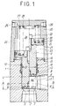
- FIG. 1 is a vertical sectional view showing in the left half a first embodiment of a two-port valve according to the present invention in a closed state of the valve and showing in the right half the valve in an open state.
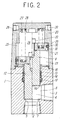
- FIG. 2 is a vertical sectional view showing in the left half a second embodiment of the valve of the invention in a closed state and showing in the right half the valve in an open state.
- FIGS. 3a to 3c are explanatory views showing possible shapes for an output-side connecting hole 6 of an output port 3 of the valve of FIGS. 1 and 2.
- FIG. 1 shows an embodiment of a two-port valve according to the invention.
- This two-port valve is mainly suitable for use in a state in which the valve is connected to a duct for liquid including a large amount of foreign matter such as refuse and abatement of a machine tool.
- the valve of the embodiment is a pilot-type two-port valve and has a casing 1 having a rectangular or circular section.
- the casing 1 has an input port 2 which opens in an axial one end face of the casing 1 and an output port 3 which opens in such a direction as to be orthogonal to an axis of the casing 1 in a side face of the casing 1.
- an L-shaped flow path 4 which communicates with the input port 2 and the output port 3 respectively through connecting holes 5 and 6 is formed.
- the connecting holes 5 and 6 are formed to have cross-sectional areas similar to those of the respective ports 2 and 3 in such a manner that the cross-sectional areas of the connecting holes 5 and 6 are substantially equal to or slightly smaller than those of the corresponding ports 2 and 3.
- an annular valve seat 7 is formed around the input-side connecting hole 5 connecting the input port 2 and the flow path 4 and a valve body 8 for opening and closing the valve seat 7 from a flow path 4 side is disposed.
- the valve body 8 is mounted to a tip end of a valve shaft 9 in a circular-cylindrical shape which is supported for sliding in the casing 1 and driven by pilot fluid pressure (air pressure).
- the input port 2, input-side connecting hole 5, valve body 8, and valve shaft 9 are disposed on the same axis.
- a flow path section in the casing 1 is set to be sufficiently large and a flow path in which a vortex-shaped flow is suppressed is formed.
- valve shaft 9 having at the tip end thereof the valve body 8 is inserted for sliding in a liquid-tight state into a sliding hole 12 provided to the casing 1 and a tip end portion of the valve shaft 9 projects and sinks into and from the flow path 4.
- the valve body 8 has at a periphery thereof an annular valve sealing portion 8a which comes in contact with and separates from the valve seat 7.
- the valve body 8 is mounted to the tip end of the valve shaft 9 through a bolt 10 and the valve body 8 moves across a front face of the output-side connecting hole 6 in opening and closing of the valve seat 7 by the valve body 8. Because the valve body 8 may be damaged by foreign matter such as refuse, it is preferable that the valve body 8 can be changed by means of the bolt 10.
- the valve body 8 is not necessarily exchangeable and it is possible that the valve body 8 is integrated with the valve shaft 9 and that a valve sealing portion 9a is formed around the tip end of the valve shaft 9 as shown in an embodiment in FIG. 2, for example.
- the sliding hole 12 into which the valve shaft 9 is fitted is formed to extend from a rear end face of the casing 1 to reach the flow path 4 and the valve shaft 9 is inserted into the sliding hole 12 from the rear end face side of the casing 1.
- a scraper 13 for suppressing entering of the foreign matter from the flow path is provided to a position of the sliding hole 12 close to the flow path 4. Behind the scraper 13, a sealant 14 for sealing against liquid entering from the flow path and a sealant 15 for sealing against pilot fluid pressure from a pressure chamber 23 which will be described below are provided.
- a reference numeral 16 designates a guide bushing.
- the valve shaft 9 in the embodiment in FIG. 1 has a diameter D1 equal to or slightly larger than a diameter D2 of the valve body 8.
- the valve body is not provided with a special reference numeral because the valve body is integrated with the valve shaft 9 but the diameters of the valve shaft 9 and the valve body are substantially the same.
- a stroke A of the valve body 8 for opening and closing the valve seat 7 is set at an amount required to substantially fully open the output-side connecting hole 6 of the output port 3 in the flow path 4. In other words, the stroke A of the valve shaft 9 is set at such an amount as to move the valve body 8 rearward to a position completely off the output-side connecting hole 6 in opening of the valve seat 7.
- FIGS. 3a to 3c show examples of a preferable shape of the output-side connecting hole 6.
- Shapes of the output-side connecting hole 6 shown in FIGS. 3a and 3b are rectangles or shapes similar to the rectangles and have widths C substantially equal to or larger than the diameter of the valve body 8 or the valve shaft 9. By forming the output-side connecting hole 6 into such a shape, a flow path section can be made as large as possible.
- a length of the flow path 4 in an axial direction of the valve shaft is set at an amount similar to a diameter B of the output-side connecting hole 6 in the axial direction, i.e., a height B in such a manner that the length of the flow path 4 is substantially the same as or slightly larger than the height B in the embodiments shown in the drawings, there is a relationship, A ⁇ B between the stroke A (FIG. 1) for fully opening the valve body 8 and the height B of the output-side connecting hole 6.
- An inside diameter of the flow path 4 is formed to be slightly larger than a diameter of the valve shaft 9 such that the valve shaft 9 is fitted in the flow path 4 with a small gap around the valve shaft 9.
- the diameter D1 of the valve shaft 9 is set to be equal to or slightly larger than the diameter D2 of the valve body 8 as described above and the valve body is moved to such a position that the output-side connecting hole 6 of the output port 3 is fully open, the valve body 8 substantially sinks into the sliding hole 12 of the casing 1 in an open state of the valve, a section of the flow path from the input port 2 to the output port 3 becomes a maximum size, and generation of the vortex-shaped flow is suppressed. Therefore, the foreign matter does not build up in a portion of the flow path 4.
- the diameter of the valve shaft 9 projecting and sinking from and into the sliding hole 12 into and from the flow path 4 is set to be equal to or slightly larger than the diameter of the valve body 8 such that there is hardly a gap between the valve body 8 and the sliding hole 12, a stagnation portion or a portion where the foreign matter gets tangled with the valve body 8 is not generated in a portion of the flow path 4 in the casing 1, which also prevents the foreign matter from building up in the flow path.
- a cover 20 is detachably mounted to a rear end portion of the casing 1, a cylinder portion is formed in the cover 20, and a piston 21 is housed for sliding in the cylinder portion.
- a rear end portion of the valve shaft 9 extends from the sliding hole 12 into the cylinder portion and connected to the piston 21 through a bolt 22.
- the pressure chamber 23 and a spring chamber 24 are defined and formed on opposite sides of the piston 21 and the pressure chamber 23 communicates with a pilot port 26 through a pilot through hole 25.
- First and second springs 27 and 28 are disposed between the cover 20 and a recessed portion of the piston in the spring chamber 24 and the spring chamber 25 is open to an outside through a breathing port 29.
- the cylinder portion is formed in the cover 20 detachably mounted onto the casing 1 and the valve body 8 is formed to have the diameter equal to or smaller than that of the valve shaft 9 as described above, it is possible to insert and detach the valve shaft 9 and the valve body 8 into and from the sliding hole 12 from outside the casing 1 in a state in which the cover 20 is detached and an assembling property, a disassembling property, and a maintainability of the valve body 8 which is liable to be damaged by the foreign matter such as refuse are excellent.
- valve sealing portion 8a (9b in the embodiment in FIG. 2) of the valve body 8 is pressed against the valve seat 7 by biasing forces of the first and second springs 27 and 28 acting on the piston 21 to close the flow path 4.
- the stroke A of the valve body 8 for opening and closing the valve seat 7 is set to be equal to the stroke required to substantially fully open the output-side connecting hole 6 connecting the output port 3 and the flow path 4, i.e., the height B of the output-side connecting hole 6, the flow path extending from the input port 2 to reach the output port 3 in the casing 1 achieves a maximum size when the valve is open and the vortex-shaped flow is suppressed. Therefore, if the two-port valve is used in a duct for fluid including a large amount of foreign matter such as refuse, the foreign matter does not build up in the flow path.
- the diameter D1 of the valve shaft 9 projecting and sinking from and into the casing 1 into and from the flow path 4 is set to be equal to or slightly larger than the diameter D2 of the valve body 8, the stagnation portion or the portion where the foreign matter gets tangled with the valve body is not generated in the flow path 4 in the casing 1, which also prevents the foreign matter from building up in the flow path.
- the two-port valve is formed by structurally modifying a conventionally known pilot-type valve, the two-port valve has the simple structure and can be provided at a low price as compared with a ball valve or the like conventionally used for fluid including foreign matter.
- a pilot-type two-port valve as described above in detail is inexpensive and has a simple structure in which the foreign matter does not get tangled with the valve body or the valve shaft or does not build up in a portion of the flow path if the two-port valve is used in the duct for fluid including the large amount of foreign matter such as refuse.
- the valve body can be easily inserted and detached from outside the casing to thereby improve the assembling property, the disassembling property, and the maintainability of the valve body which is liable to be damaged by the foreign matter such as refuse.
Landscapes
- Engineering & Computer Science (AREA)
- General Engineering & Computer Science (AREA)
- Mechanical Engineering (AREA)
- Lift Valve (AREA)
- Details Of Valves (AREA)
- Fluid-Driven Valves (AREA)
Applications Claiming Priority (2)
| Application Number | Priority Date | Filing Date | Title |
|---|---|---|---|
| JP2000086922 | 2000-03-27 | ||
| JP2000086922A JP3758934B2 (ja) | 2000-03-27 | 2000-03-27 | 2ポートバルブ |
Publications (3)
| Publication Number | Publication Date |
|---|---|
| EP1138988A2 true EP1138988A2 (fr) | 2001-10-04 |
| EP1138988A3 EP1138988A3 (fr) | 2002-10-09 |
| EP1138988B1 EP1138988B1 (fr) | 2006-01-11 |
Family
ID=18603017
Family Applications (1)
| Application Number | Title | Priority Date | Filing Date |
|---|---|---|---|
| EP01302739A Expired - Lifetime EP1138988B1 (fr) | 2000-03-27 | 2001-03-22 | Soupape à deux voies |
Country Status (7)
| Country | Link |
|---|---|
| US (1) | US6655651B2 (fr) |
| EP (1) | EP1138988B1 (fr) |
| JP (1) | JP3758934B2 (fr) |
| KR (1) | KR100522499B1 (fr) |
| CN (1) | CN1223776C (fr) |
| DE (1) | DE60116567T2 (fr) |
| TW (1) | TW461476U (fr) |
Families Citing this family (4)
| Publication number | Priority date | Publication date | Assignee | Title |
|---|---|---|---|---|
| JP4445238B2 (ja) * | 2003-10-09 | 2010-04-07 | シーケーディ株式会社 | 流体制御弁 |
| US20070057214A1 (en) * | 2005-09-09 | 2007-03-15 | Vat Holding Ag | Valve for essentially gastight closing a flow path |
| KR101424114B1 (ko) * | 2005-10-05 | 2014-08-01 | 고옌 콘트롤즈 컴퍼니 피티와이 리미티드 | 고압 공기 펄스의 제어 밸브 |
| US8100149B2 (en) * | 2007-09-24 | 2012-01-24 | Griswold Controls Inc | Combined pressure, temperature and air vent device |
Family Cites Families (12)
| Publication number | Priority date | Publication date | Assignee | Title |
|---|---|---|---|---|
| GB234206A (en) | 1924-03-04 | 1925-05-28 | Michael Ratcliffe Barnett | Improvements in and relating to waterworks pillar taps and the like |
| FR865659A (fr) | 1940-05-16 | 1941-05-30 | Martin | Dispositif de commande pneumatique avec signalisation générale pour canalisations |
| US2634754A (en) * | 1948-12-27 | 1953-04-14 | Oil Ct Tool Company | Pilot controlled fluid pressure operated valve |
| US3224817A (en) * | 1962-08-13 | 1965-12-21 | Carter Controls Inc | Cylinder and piston arrangement |
| US3542332A (en) | 1968-11-22 | 1970-11-24 | Alain A Chevalier | Air operated poppet seat valve |
| DE2326609C3 (de) | 1973-05-24 | 1978-06-22 | Paul 5419 Doettesfeld Kunz | Dampfschälanlage mit einem Druckbehälter |
| US3955796A (en) * | 1975-02-12 | 1976-05-11 | M & J Valve Company | Flow control apparatus |
| US4257442A (en) * | 1976-09-27 | 1981-03-24 | Claycomb Jack R | Choke for controlling the flow of drilling mud |
| US4355784A (en) * | 1980-08-04 | 1982-10-26 | Warren Automatic Tool Company | Method and apparatus for controlling back pressure |
| WO1997004262A1 (fr) * | 1995-07-18 | 1997-02-06 | Tiefenbach Gmbh | Soupape hydraulique pilotee de fermeture |
| US5762316A (en) * | 1995-10-04 | 1998-06-09 | Kraft Foods, Inc. | Valve mechanism with improved sealing |
| JP4247567B2 (ja) | 2000-01-06 | 2009-04-02 | Smc株式会社 | 2ポート弁 |
-
2000
- 2000-03-27 JP JP2000086922A patent/JP3758934B2/ja not_active Expired - Fee Related
-
2001
- 2001-03-05 TW TW090203247U patent/TW461476U/zh not_active IP Right Cessation
- 2001-03-12 US US09/802,915 patent/US6655651B2/en not_active Expired - Fee Related
- 2001-03-22 EP EP01302739A patent/EP1138988B1/fr not_active Expired - Lifetime
- 2001-03-22 DE DE60116567T patent/DE60116567T2/de not_active Expired - Fee Related
- 2001-03-27 CN CNB011120304A patent/CN1223776C/zh not_active Expired - Fee Related
- 2001-03-27 KR KR10-2001-0015881A patent/KR100522499B1/ko not_active Expired - Fee Related
Non-Patent Citations (1)
| Title |
|---|
| None |
Also Published As
| Publication number | Publication date |
|---|---|
| DE60116567D1 (de) | 2006-04-06 |
| KR20010090578A (ko) | 2001-10-18 |
| US20010023929A1 (en) | 2001-09-27 |
| CN1223776C (zh) | 2005-10-19 |
| KR100522499B1 (ko) | 2005-10-18 |
| EP1138988A3 (fr) | 2002-10-09 |
| JP3758934B2 (ja) | 2006-03-22 |
| US6655651B2 (en) | 2003-12-02 |
| CN1319734A (zh) | 2001-10-31 |
| EP1138988B1 (fr) | 2006-01-11 |
| JP2001271959A (ja) | 2001-10-05 |
| DE60116567T2 (de) | 2006-09-07 |
| TW461476U (en) | 2001-10-21 |
Similar Documents
| Publication | Publication Date | Title |
|---|---|---|
| US6796545B2 (en) | Poppet valve seal mechanism | |
| US8550117B2 (en) | Seal assembly for a fluid pressure control device | |
| KR100389534B1 (ko) | 2포트 밸브 | |
| MY137044A (en) | Control valve trim and bore seal | |
| KR20010070404A (ko) | 파일롯형 2포트 밸브 | |
| JP4189711B2 (ja) | 2ポート弁 | |
| CA2604947A1 (fr) | Vanne de regulation du flux de liquide avec joint | |
| EP1138988B1 (fr) | Soupape à deux voies | |
| KR100857611B1 (ko) | 롱 플레이트 슬라이드 나이프 게이트 밸브 | |
| US7309058B2 (en) | Flexible backseat seal for gate valve | |
| JP5767124B2 (ja) | 制御弁 | |
| KR20060043814A (ko) | 개폐 밸브 및 진공 챔버의 개구부의 개폐 방법 | |
| KR20020020842A (ko) | 개폐밸브 | |
| KR102460690B1 (ko) | 진공밸브 | |
| KR100338178B1 (ko) | 볼밸브등의 기밀유지용시트어셈블리 | |
| US20240353014A1 (en) | Integrated dot pressure protection valve | |
| CN115076587B (zh) | 油罐及油脂润滑泵 | |
| CN214063452U (zh) | 阀芯密封结构、阀门和顺序油缸 | |
| JP4424674B2 (ja) | 減圧弁 | |
| JP2652470B2 (ja) | 調節弁 | |
| JPH0726621Y2 (ja) | 切換弁における弁棒のシール機構 | |
| KR100342986B1 (ko) | 에어 건 | |
| AU2011204925B2 (en) | Ventil |
Legal Events
| Date | Code | Title | Description |
|---|---|---|---|
| PUAI | Public reference made under article 153(3) epc to a published international application that has entered the european phase |
Free format text: ORIGINAL CODE: 0009012 |
|
| 17P | Request for examination filed |
Effective date: 20010405 |
|
| AK | Designated contracting states |
Kind code of ref document: A2 Designated state(s): AT BE CH CY DE DK ES FI FR GB GR IE IT LI LU MC NL PT SE TR |
|
| AX | Request for extension of the european patent |
Free format text: AL;LT;LV;MK;RO;SI |
|
| PUAL | Search report despatched |
Free format text: ORIGINAL CODE: 0009013 |
|
| AK | Designated contracting states |
Kind code of ref document: A3 Designated state(s): AT BE CH CY DE DK ES FI FR GB GR IE IT LI LU MC NL PT SE TR |
|
| AX | Request for extension of the european patent |
Free format text: AL;LT;LV;MK;RO;SI |
|
| AKX | Designation fees paid |
Designated state(s): DE FR GB IT |
|
| GRAP | Despatch of communication of intention to grant a patent |
Free format text: ORIGINAL CODE: EPIDOSNIGR1 |
|
| GRAS | Grant fee paid |
Free format text: ORIGINAL CODE: EPIDOSNIGR3 |
|
| GRAA | (expected) grant |
Free format text: ORIGINAL CODE: 0009210 |
|
| AK | Designated contracting states |
Kind code of ref document: B1 Designated state(s): DE FR GB IT |
|
| PG25 | Lapsed in a contracting state [announced via postgrant information from national office to epo] |
Ref country code: IT Free format text: LAPSE BECAUSE OF FAILURE TO SUBMIT A TRANSLATION OF THE DESCRIPTION OR TO PAY THE FEE WITHIN THE PRE;WARNING: LAPSES OF ITALIAN PATENTS WITH EFFECTIVE DATE BEFORE 2007 MAY HAVE OCCURRED AT ANY TIME BEFORE 2007. THE CORRECT EFFECTIVE DATE MAY BE DIFFERENT FROM THE ONE RECORDED.SCRIBED TIME-LIMIT Effective date: 20060111 |
|
| PGFP | Annual fee paid to national office [announced via postgrant information from national office to epo] |
Ref country code: FR Payment date: 20060331 Year of fee payment: 6 |
|
| REF | Corresponds to: |
Ref document number: 60116567 Country of ref document: DE Date of ref document: 20060406 Kind code of ref document: P |
|
| PGFP | Annual fee paid to national office [announced via postgrant information from national office to epo] |
Ref country code: GB Payment date: 20060420 Year of fee payment: 6 |
|
| PLBE | No opposition filed within time limit |
Free format text: ORIGINAL CODE: 0009261 |
|
| STAA | Information on the status of an ep patent application or granted ep patent |
Free format text: STATUS: NO OPPOSITION FILED WITHIN TIME LIMIT |
|
| 26N | No opposition filed |
Effective date: 20061012 |
|
| EN | Fr: translation not filed | ||
| GBPC | Gb: european patent ceased through non-payment of renewal fee |
Effective date: 20070322 |
|
| PG25 | Lapsed in a contracting state [announced via postgrant information from national office to epo] |
Ref country code: GB Free format text: LAPSE BECAUSE OF NON-PAYMENT OF DUE FEES Effective date: 20070322 Ref country code: FR Free format text: LAPSE BECAUSE OF FAILURE TO SUBMIT A TRANSLATION OF THE DESCRIPTION OR TO PAY THE FEE WITHIN THE PRESCRIBED TIME-LIMIT Effective date: 20070302 |
|
| PGFP | Annual fee paid to national office [announced via postgrant information from national office to epo] |
Ref country code: DE Payment date: 20090320 Year of fee payment: 9 |
|
| PG25 | Lapsed in a contracting state [announced via postgrant information from national office to epo] |
Ref country code: DE Free format text: LAPSE BECAUSE OF NON-PAYMENT OF DUE FEES Effective date: 20101001 |