EP1139059B1 - Dispositif d'allumage d'un système de sécurité - Google Patents
Dispositif d'allumage d'un système de sécurité Download PDFInfo
- Publication number
- EP1139059B1 EP1139059B1 EP01107005A EP01107005A EP1139059B1 EP 1139059 B1 EP1139059 B1 EP 1139059B1 EP 01107005 A EP01107005 A EP 01107005A EP 01107005 A EP01107005 A EP 01107005A EP 1139059 B1 EP1139059 B1 EP 1139059B1
- Authority
- EP
- European Patent Office
- Prior art keywords
- housing
- ignition
- initiation
- stamped
- safety system
- Prior art date
- Legal status (The legal status is an assumption and is not a legal conclusion. Google has not performed a legal analysis and makes no representation as to the accuracy of the status listed.)
- Expired - Lifetime
Links
Images


Classifications
-
- F—MECHANICAL ENGINEERING; LIGHTING; HEATING; WEAPONS; BLASTING
- F42—AMMUNITION; BLASTING
- F42B—EXPLOSIVE CHARGES, e.g. FOR BLASTING, FIREWORKS, AMMUNITION
- F42B3/00—Blasting cartridges, i.e. case and explosive
- F42B3/10—Initiators therefor
- F42B3/103—Mounting initiator heads in initiators; Sealing-plugs
-
- B—PERFORMING OPERATIONS; TRANSPORTING
- B60—VEHICLES IN GENERAL
- B60R—VEHICLES, VEHICLE FITTINGS, OR VEHICLE PARTS, NOT OTHERWISE PROVIDED FOR
- B60R21/00—Arrangements or fittings on vehicles for protecting or preventing injuries to occupants or pedestrians in case of accidents or other traffic risks
- B60R21/02—Occupant safety arrangements or fittings, e.g. crash pads
- B60R21/16—Inflatable occupant restraints or confinements designed to inflate upon impact or impending impact, e.g. air bags
- B60R21/26—Inflatable occupant restraints or confinements designed to inflate upon impact or impending impact, e.g. air bags characterised by the inflation fluid source or means to control inflation fluid flow
- B60R2021/26029—Ignitors
Definitions
- the invention relates to an ignition device for a safety system, which is in particular an airbag or a belt tensioner of a vehicle, according to the features of the preamble of claim 1.
- a drive device for restraint systems in motor vehicles is already known.
- This consists of a housing with a cylinder in which a piston is movably arranged.
- the piston is pushed out of the cylinder when a working chamber of the housing has been pressurized by igniting a propellant charge.
- the propellant charge is arranged in a partial region of the housing and is separated from the working chamber by a so-called bursting floor.
- Within the propellant charge there is a priming charge which, when the primer has been ignited, causes the propellant charge to explode.
- the propellant charge in which the ignition charge is inserted, is housed in a portion of the housing and is separated by a spacer sleeve of this portion of the housing.
- the ignition charge is connected by very thin leads to a control device.
- the portion of the housing in which the propellant charge is arranged is closed by a cap.
- DE 196 09 908 A relates to an ignition device for a safety system, in particular an airbag or a belt tensioner of a vehicle, with a connecting means, in particular connecting lines, ignitable ignition element, wherein the ignition element is arranged and pre-assembled with the connection means in a Zündgephinuse, wherein the ignition element Having contact lugs, wherein at least one of the contact lugs of the ignition element via electrically conductive connection means with one of the connection means, in particular one end of the connecting line, is connected.
- the invention is therefore based on the object to avoid the disadvantages described above.
- the electrically conductive connection means are formed as stamped parts.
- the ignition element with the connection means in particular the connection lines, is arranged and preassembled in a separate ignition housing. Ie. A preassembled unit is available which can already be checked for proper functioning before it is installed. In addition, it is possible to pre-assemble this igniter, regardless of the security system used and the location of the security system, so that there is a higher flexibility in terms of production, since the manufacturer of the ignition device does not necessarily have to be the manufacturer of the security system. If the ignition device has been checked for its function, it can be installed in the propellant charge in the safety system without further testing.
- the ignition element is generally one
- Trigger element for electrically operated pyrotechnic-based safety devices, wherein the safety devices are in particular airbags or belt tensioners of vehicles.
- ignition element both immersed ignition heads and lighters in glass / metal design or the like can be used.
- the ignition element on contact lugs By means of these tabs, it is possible to attach the ends of the leads directly to these tabs, in particular by soldering or welding. Optionally, a mechanical connection, in particular crimping, are used.
- At least one of the contact lugs of the ignition element via electrically conductive connecting means, namely stampings, with one of the connecting means, in particular one end of a connecting line connected.
- electrically conductive connecting means namely stampings
- one of the connecting means in particular one end of a connecting line connected.
- this is a coil or throttle, can be derived by means of the misfires in consequence of resulting by irradiated electromagnetic fields voltages or currents or conducted RF waves.
- components such as capacitors, varistors or the like. This is due to the compactness in particular SMD components.
- the components can also be configured as alternatives or in addition to the connecting means.
- stamped parts as electrically conductive connecting means thus has the advantage that the stamped parts can be automatically fed and processed and at the same time the electrical contact between the components involved is produced.
- At least one connecting means in particular one of the stamped parts, is designed as an electrode.
- the formed as an electrode stamped part or several stamped parts are led out of the ignition and form with the housing of the safety system a spark gap over which voltages can be derived, which would otherwise lead in the case of Tinabtechnisch to trigger the ignition element.
- the compactness is further increased by the use of a stamped part as an electrode while increasing the functionality.
- At least the ignition element, the connecting means (stamped parts) and the ends of the connecting means in an open housing, in particular a half-shell, are arranged.
- this open housing which can also be supplied automatically, the positions of the ignition element, the connecting means and the ends of the connecting means are given in particular by a profiling of the inner contour, so that predefined after the onset of the components in the open housing, the position of the components involved is and the contacting can be automated.
- At least the connecting means in particular the stamped parts, are arranged in a molded housing.
- the stamped parts are fixed in position and then the housing is produced in a plastic injection molding process or in another suitable method, so that after the overmolding a preassembled unit is formed.
- This assembly can be automatically fed to the next process step and further processed there.
- the insertion and contacting of electronic components with the stamped parts takes place in the next method step.
- the overmolded housing is an open housing, so that the stamped parts are accessible for insertion and contacting of the components.
- the open housing is closed with a corresponding lid. Does the cover as inner contours on the outer contours of the open housing including the components involved, a pouring can be dispensed with. If this is not the case, d. h., There are still spaces between the inner contour of the lid and the outer contour of the open housing with its components involved, offers the pouring with a potting compound. This also results in the same advantages as in the casting of the open housing with a potting compound.
- the ignition housing for example, consist of at least two housing halves, in which the closed housing is used with the ignition element and the leads.
- the sealed housing is molded with the ignition element and its leads and the electrode, resulting from the encapsulation of the ignition.
- the rigid basic structure again has an advantageous effect, since by encapsulating neither the ignition element nor the components involved (stamped parts, etc.) can be damaged or impaired in their function.
- Due to the basic structure of the closed, previously open housing it is also possible to insert this basic structure automatically in the injection mold.
- the surrounding of the sealed housing with the ignition housing also gives the entire structure an additional tightness.
- the outer contours of the ignition housing are designed so that an automated further processing such as testing and installation in the security system is possible.
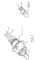
- FIG. 1 shows an ignition device 1, which can be produced and tested as a preassembled unit.
- This ignition device 1 is installed as a preassembled unit at the corresponding location of the safety system of the airbag or the belt tensioner or the like in the vehicle.
- the ignition device 1 comprises an ignition element 2, which can be acted upon with an electrical pulse to bring a propellant charge (not shown here) of the safety system to explode.
- a propellant charge not shown here
- the ignition element 2 is seated on an end face of an ignition housing 3, with which the ignition device 1 can be installed in a likewise not shown housing of the safety system. Connecting lines 4 and 5, via which the ignition element 2 receives its pulse, are led out of this at the opposite end face of the ignition housing 3, but can also be led out of this ignition housing 3 at any other point.
- Figure 1 is still shown that protrude from the ignition housing 3, an electrode 6 (or more), which after installation in the housing of the security system have a certain distance from the housing, so that formed a spark gap between the electrode 6 and the housing is within which a sparkover can take place when, as a result of static charges voltages between the housing and the leads 4 and 5 occur. This derivation of the static charge has the advantage that thereby the unwanted ignition of the ignition element 2 is avoided.
- the outer contours of the ignition housing 3 are chosen so that they allow a mechanical handling of the ignition device 1, so that the ignition device 1 can be easily inserted and fixed in the housing of the safety system and also provides a kink protection for the leads 4 and 5.
- FIG. 2 shows the configuration of the ignition element 2, which consists of a head with the ignition charge and contact lugs 7 and 8 for the electrical contact.
- Such an ignition element 2 can be prefabricated and can be easily fed to the next step due to the stiff contact lugs 7 and 8.
- FIG. 3 shows as the next work step the insertion of the ignition element 2 into an open housing, which is designed as a half-shell 9.
- punched parts 10 to 12 are then used, on the one hand accept the contact between the contact lugs 7 and 8 and the ends of the leads 4 and 5 and continue to form the electrodes.
- the outwardly projecting stamped parts 11 and 12 form the later electrodes 6, which protrude from the ignition housing 3.
- the stamped part 10 is contacted as a connecting means and the stamped part 11 as a later electrode 6 at the contact lug 7.
- the stamped part 12 is clamped on the half-shell 9 due to its geometric shape (as well as the stamped part 11).
- an electronic component such as a throttle
- the stamped parts and the other components involved are effectively set in the half-shell 9, so that they can be contacted thereafter.
- the half-shell 9 has in addition to receiving the ends of the leads 4 and 5 each have an exception 13.
- Figure 4 shows the next processing step, wherein it is visible that the ends of the leads 4 and 5 have been embedded in the exceptions 13 so that the electrically conductive ends of the leads 4 and 5 can be contacted with the corresponding configured opposing parts of the stampings 11 and 12 ,
- a rod core choke 14 between the contact lug 8 of the ignition element 2 and the stamped part 12 is inserted and mitromeiert also. It can also first the rod core choke 14 (and / or other components) and then the stamped parts are used; then the contact takes place.
- FIG. 5 shows that the arrangement produced according to FIG. 4 is provided with a potting compound 15.
- This potting compound 15 can also be injected automatically into the open half-shell 9 and increases the strength and gives protection against environmental influences, the longitudinal water-tightness along the leads 4 and 5 in the direction of the ignition element 2 is particularly noteworthy.
- This longitudinal water-tightness is given by the fact that a part of the sheath of the leads 4 and 5, which is located in the exceptions 13, is enclosed by the potting compound 15 with.
- the arrangement shown in FIG. 5 can also be automatically fed to the next processing step, this arrangement being overmolded by the ignition housing 3 or being inserted into a suitably configured ignition housing 3.
- the ignition housing 3 consists of two or more parts, which receive the arrangement of Figure 5 and are then joined together with a further potting compound.
- FIGS. 6 to 8 show, analogously to the method steps shown and described in FIGS. 3 to 5, alternative method steps for producing the ignition device.
- FIG. 6 shows the presence of punched parts 16 and 17, which at their ends have terminal lugs 18 and 19 for the connection lines 4 and 5 as well as terminal lugs 20 and 21 for the contact lugs 7 and 8 of the ignition element 2.
- terminal lugs 18 to 21 or some of the stamped parts 16 and 17 can be fixed in position to produce in a plastic injection molding process or other suitable method, a molded housing 22 which surrounds the stampings 16 and 17 at least partially and is open at the top.
- FIG. 7 shows the next method step, in which the manufactured assembly shown in FIG. 6 is provided with electronic components 23 which can be automatically fed to the overmolded housing 22. After the supply of the electronic components, these are contacted in circuit-technically meaningful manner (for example by parallel connection) with the stamped parts 16 and 17.
- Figure 8 shows the subsequent process step, in which the terminal lugs 18 and 19 of the stampings 16 and 17 are contacted with the stranded ends of the leads 4 and 5. Likewise, a contacting of the terminal lugs 7 and 8 of the ignition element 2 with the terminal lugs 20 and 21. After this is done, before the overmolded housing 22 is closed, take place an electrical functional test. If such a functional test is not or is completed positively, the overmolded housing 22 can be closed or automatically fed without closure to the next processing step. In this processing step, the arrangement shown in FIG. 8 is encapsulated by the ignition housing 3 (FIG. 1) or inserted into a suitably configured ignition housing 3. This also creates an ignition device, as shown in Figure 1.
- This ignition device has in addition to the already described advantage the further advantage that it is possible with the help of both as electrodes 6 out of the ignition housing 3 punched parts 11 and 12 regardless of the length of the leads 4 and 5 and the execution of the ignition element 2 and the integrated components is to check the ignition device 1 for their electrical functionality. Because it has been shown that the safety system (ie, the housing with the integrated ignition device) and the control device, is generated spatially separated from the depending on certain conditions of the trigger pulse from. Although it would still be possible to check the functionality of the ignition device via the leads 4 and 5. However, this hampers an automated test, since the ends of the leads 4 and 5 must be contacted manually with a test unit. Due to the inventive arrangement of the electrodes 6 in the ignition housing 3, this unit can be inserted into a corresponding receptacle of the test unit or automatically tapped the two electrodes 6 to perform the test.
- leads pins are used, which are parts of a plug or a socket. In this case, it could be thought that the ignition housing 3 with the pins forms the plug or socket.
Landscapes
- Engineering & Computer Science (AREA)
- General Engineering & Computer Science (AREA)
- Air Bags (AREA)
Claims (9)
- Dispositif d'allumage (1) d'un système de sécurité, en particulier d'un airbag ou d'un tendeur de ceinture d'un véhicule, avec un élément d'allumage (2) pouvant être allumé via des moyens de raccordement, notamment des lignes de raccordement (4, 5), sachant que l'élément d'allumage (2) est disposé et pré-assemblé avec les moyens de raccordement dans un boîtier d'allumage (3), sachant que l'élément d'allumage (2) présente des talons de contact (7, 8), et sachant qu'au moins un des talons de contact (7) de l'élément d'allumage (2) est relié via des moyens de liaison électroconducteurs à un des moyens de raccordement, en particulier à une extrémité de la ligne de raccordement (4, 5), caractérisé en ce que les moyens de liaison électroconducteurs sont réalisés sous la forme de pièces découpées (10, 11, 16, 17).
- Dispositif d'allumage (1) selon la revendication 1, caractérisé en ce qu'au moins la pièce découpée (11, 16) est réalisée sous forme d'électrode (6) .
- Dispositif d'allumage (1) selon une quelconque des revendications précédentes, caractérisé en ce qu'au moins l'élément d'allumage (2), les moyens de liaison ainsi que les extrémités des moyens de raccordement sont disposés dans un boîtier ouvert, en particulier dans une demi-coque (9).
- Dispositif d'allumage (1) selon une quelconque des revendications précédentes, caractérisé en ce qu'au moins les moyens de liaison, en particulier les pièces découpées (16, 17), sont disposés dans un boîtier surmoulé (22).
- Dispositif d'allumage (1) selon la revendication 4, caractérisé en ce que le boîtier ouvert ou le boîtier surmoulé (22) peut être fermé par une masse de remplissage (15).
- Dispositif d'allumage (1) selon la revendication 4, caractérisé en ce que le boîtier ouvert ou le boîtier surmoulé (22) peut être fermé par un couvercle et est notamment rempli de la masse de remplissage (15).
- Dispositif d'allumage (1) selon une quelconque des revendications précédentes, caractérisé en ce que le boîtier d'allumage (3) peut entourer le boîtier fermé, en particulier est surmoulé autour de ce dernier.
- Dispositif d'allumage (1) selon une quelconque des revendications précédentes, caractérisé en ce que les pièces découpées (11, 12) sont dirigées hors du boîtier d'allumage (3) sous la forme d'électrodes (6) et peuvent le cas échéant être raccourcies.
- Dispositif d'allumage (1) selon une quelconque des revendications précédentes, caractérisé en ce que des composants électroniques (14, 22, 23) sont disposés dans le boîtier ouvert ou dans le boîtier surmoulé (22) et sont mis en contact avec une pièce découpée respective (10, 11, 16, 17).
Applications Claiming Priority (4)
| Application Number | Priority Date | Filing Date | Title |
|---|---|---|---|
| DE10015085 | 2000-03-28 | ||
| DE10015085 | 2000-03-28 | ||
| DE10111809A DE10111809A1 (de) | 2000-03-28 | 2001-03-09 | Zündvorrichtung für ein Sicherheitssystem |
| DE10111809 | 2001-03-09 |
Publications (3)
| Publication Number | Publication Date |
|---|---|
| EP1139059A2 EP1139059A2 (fr) | 2001-10-04 |
| EP1139059A3 EP1139059A3 (fr) | 2004-05-19 |
| EP1139059B1 true EP1139059B1 (fr) | 2006-07-12 |
Family
ID=26005036
Family Applications (1)
| Application Number | Title | Priority Date | Filing Date |
|---|---|---|---|
| EP01107005A Expired - Lifetime EP1139059B1 (fr) | 2000-03-28 | 2001-03-21 | Dispositif d'allumage d'un système de sécurité |
Country Status (4)
| Country | Link |
|---|---|
| US (1) | US6650528B2 (fr) |
| EP (1) | EP1139059B1 (fr) |
| AT (1) | ATE332829T1 (fr) |
| DE (1) | DE50110428D1 (fr) |
Families Citing this family (4)
| Publication number | Priority date | Publication date | Assignee | Title |
|---|---|---|---|---|
| US20030221578A1 (en) * | 2002-05-29 | 2003-12-04 | Forman David M. | Detonator with onboard electronics mechanically connected to ignition element |
| JP2004281761A (ja) * | 2003-03-17 | 2004-10-07 | Seiko Epson Corp | 半導体装置およびその製造方法 |
| US8776358B2 (en) | 2007-08-06 | 2014-07-15 | Apple Inc. | Housing components for electronic devices |
| US20110203866A1 (en) * | 2010-02-24 | 2011-08-25 | Mesa Digital, LLC. | Seatbelt safety apparatus and method for controlling ignition of automotive vehicles |
Family Cites Families (13)
| Publication number | Priority date | Publication date | Assignee | Title |
|---|---|---|---|---|
| GB404335A (en) * | 1932-07-06 | 1934-01-08 | Thames Ammunition Works Ltd | Improvements in or relating to electric blasting fuzes |
| US4213635A (en) * | 1978-11-13 | 1980-07-22 | Toyota Kodosha Kogyo Kabushiki Kaisha | Two-stage air bag system |
| US4422381A (en) * | 1979-11-20 | 1983-12-27 | Ici Americas Inc. | Igniter with static discharge element and ferrite sleeve |
| US4530516A (en) * | 1984-07-09 | 1985-07-23 | Morton Thiokol Inc. | Aluminum inflator with steel center-tie |
| US4722551A (en) * | 1987-03-19 | 1988-02-02 | Morton Thiokol, Inc. | Initiator and method for the incorporation thereof in an inflator |
| US5100170A (en) * | 1991-01-22 | 1992-03-31 | Trw Vehicle Safety Systems Inc. | Auto-ignition device for an air bag inflator |
| US5152549A (en) * | 1991-04-22 | 1992-10-06 | Trw Inc. | Vehicle safety apparatus having a retainer for clamping an inflator against a support plate |
| US5454320A (en) * | 1992-10-23 | 1995-10-03 | Quantic Industries, Inc. | Air bag initiator |
| AT522U1 (de) | 1994-03-23 | 1995-12-27 | Hirtenberger Ag | Antriebsvorrichtung fuer rueckhaltesysteme in kraftfahrzeugen |
| FR2730864B3 (fr) * | 1995-02-17 | 1997-04-30 | Amp France | Borne femelle electrique d'une seule piece |
| DE19609908A1 (de) * | 1996-03-14 | 1997-09-18 | Dynamit Nobel Ag | Gasgenerator, insbesondere für Gurtstraffer |
| US5932832A (en) * | 1996-04-15 | 1999-08-03 | Autoliv Asp, Inc. | High pressure resistant initiator with integral metal oxide varistor for electro-static discharge protection |
| US5876062A (en) * | 1997-07-29 | 1999-03-02 | Autoliv Asp, Inc. | Airbag inflator with direct electrical ignition for small sized gas generant bodies |
-
2001
- 2001-03-21 EP EP01107005A patent/EP1139059B1/fr not_active Expired - Lifetime
- 2001-03-21 AT AT01107005T patent/ATE332829T1/de active
- 2001-03-21 DE DE50110428T patent/DE50110428D1/de not_active Expired - Lifetime
- 2001-03-28 US US09/818,948 patent/US6650528B2/en not_active Expired - Fee Related
Also Published As
| Publication number | Publication date |
|---|---|
| US20020001162A1 (en) | 2002-01-03 |
| DE50110428D1 (de) | 2006-08-24 |
| US6650528B2 (en) | 2003-11-18 |
| EP1139059A2 (fr) | 2001-10-04 |
| ATE332829T1 (de) | 2006-08-15 |
| EP1139059A3 (fr) | 2004-05-19 |
Similar Documents
| Publication | Publication Date | Title |
|---|---|---|
| EP0862689B1 (fr) | Distributeur de carburant | |
| DE19936300A1 (de) | Druckerkennungsvorrichtung, Verbindungsteil hierfür, sowie Verfahren zur Herstellung eines elektrischen Bauteileverbinders | |
| DE69708196T2 (de) | Zünder mit selbstklemmendem Zweileiter-Anschluss für pyrotechnische Gasgeneratoren | |
| DE102008036399A1 (de) | Datenkabel | |
| DE19611220A1 (de) | Elektrisches Verbindungselement, Zündgerät für Verbrennungsmotor und Herstellungsverfahren hierfür | |
| DE3922267A1 (de) | Zuendvorrichtung fuer eine brennkraftmaschine | |
| DE102017124292A1 (de) | Anzünder für einen gasgenerator und verfahren zur herstellung eines anzünders | |
| EP1139059A2 (fr) | Dispositif d'allumage d'un système de sécurité | |
| EP0983478A1 (fr) | Detonateur pour un generateur de gaz pyrotechnique, et generateur de gaz pyrotechnique | |
| DE10111809A1 (de) | Zündvorrichtung für ein Sicherheitssystem | |
| DE102012004966B3 (de) | Zündsockel für pyroelektrische Zündvorrichtungen | |
| DE29502977U1 (de) | Stecker zur Kontaktierung einer Gasentladungslampe | |
| EP1715195B1 (fr) | Unité de initiateur pour un système de sécurité, notamment pour un sac gonflable ou un prétensionneur de véhicule | |
| EP1160534B1 (fr) | Allumeur pour système de sécurité | |
| DE102016219421A1 (de) | Gehäuse mit Zugentlastung für ein Kabel | |
| DE102004027510A1 (de) | Kontakthalter zur Herstellung einer Klemmkontaktierung | |
| EP1460371B1 (fr) | Initiateur pyrotechnique et son procédé de fabrication | |
| DE102019214606A1 (de) | Elektronikmodul | |
| DE202004011348U1 (de) | Zündeinrichtung für einen Gasgenerator | |
| DE102021110681B3 (de) | Steckverbindung für Airbag-Zündsysteme | |
| DE19522657C2 (de) | Entstörstecker für eine Zündanlage einer Brennkraftmaschine | |
| DE102012101232B4 (de) | Glühkerzensteckverbinder | |
| EP1477764A1 (fr) | Allumeur pour l'utilisation dans une dispositif de protection pour des occupants d'un véhicule | |
| DE102011112755A1 (de) | Elektro-Magnet | |
| DE102017210979B4 (de) | Verfahren zur Herstellung eines elektrischen Bauteils und elektrisches Bauteil |
Legal Events
| Date | Code | Title | Description |
|---|---|---|---|
| PUAI | Public reference made under article 153(3) epc to a published international application that has entered the european phase |
Free format text: ORIGINAL CODE: 0009012 |
|
| AK | Designated contracting states |
Kind code of ref document: A2 Designated state(s): AT BE CH CY DE DK ES FI FR GB GR IE IT LI LU MC NL PT SE TR |
|
| AX | Request for extension of the european patent |
Free format text: AL;LT;LV;MK;RO;SI |
|
| PUAL | Search report despatched |
Free format text: ORIGINAL CODE: 0009013 |
|
| AK | Designated contracting states |
Kind code of ref document: A3 Designated state(s): AT BE CH CY DE DK ES FI FR GB GR IE IT LI LU MC NL PT SE TR |
|
| AX | Request for extension of the european patent |
Extension state: AL LT LV MK RO SI |
|
| RIC1 | Information provided on ipc code assigned before grant |
Ipc: 7B 60R 21/26 A Ipc: 7B 60R 22/46 B |
|
| RAP1 | Party data changed (applicant data changed or rights of an application transferred) |
Owner name: HIRSCHMANN AUTOMOTIVE GMBH |
|
| 17P | Request for examination filed |
Effective date: 20040901 |
|
| AKX | Designation fees paid |
Designated state(s): AT BE CH CY DE DK ES FI FR GB GR IE IT LI LU MC NL PT SE TR |
|
| 17Q | First examination report despatched |
Effective date: 20050705 |
|
| GRAP | Despatch of communication of intention to grant a patent |
Free format text: ORIGINAL CODE: EPIDOSNIGR1 |
|
| GRAS | Grant fee paid |
Free format text: ORIGINAL CODE: EPIDOSNIGR3 |
|
| GRAA | (expected) grant |
Free format text: ORIGINAL CODE: 0009210 |
|
| AK | Designated contracting states |
Kind code of ref document: B1 Designated state(s): AT BE CH CY DE DK ES FI FR GB GR IE IT LI LU MC NL PT SE TR |
|
| PG25 | Lapsed in a contracting state [announced via postgrant information from national office to epo] |
Ref country code: IT Free format text: LAPSE BECAUSE OF FAILURE TO SUBMIT A TRANSLATION OF THE DESCRIPTION OR TO PAY THE FEE WITHIN THE PRE;WARNING: LAPSES OF ITALIAN PATENTS WITH EFFECTIVE DATE BEFORE 2007 MAY HAVE OCCURRED AT ANY TIME BEFORE 2007. THE CORRECT EFFECTIVE DATE MAY BE DIFFERENT FROM THE ONE RECORDED.SCRIBED TIME-LIMIT Effective date: 20060712 Ref country code: GB Free format text: LAPSE BECAUSE OF FAILURE TO SUBMIT A TRANSLATION OF THE DESCRIPTION OR TO PAY THE FEE WITHIN THE PRESCRIBED TIME-LIMIT Effective date: 20060712 Ref country code: FI Free format text: LAPSE BECAUSE OF FAILURE TO SUBMIT A TRANSLATION OF THE DESCRIPTION OR TO PAY THE FEE WITHIN THE PRESCRIBED TIME-LIMIT Effective date: 20060712 Ref country code: NL Free format text: LAPSE BECAUSE OF FAILURE TO SUBMIT A TRANSLATION OF THE DESCRIPTION OR TO PAY THE FEE WITHIN THE PRESCRIBED TIME-LIMIT Effective date: 20060712 Ref country code: IE Free format text: LAPSE BECAUSE OF FAILURE TO SUBMIT A TRANSLATION OF THE DESCRIPTION OR TO PAY THE FEE WITHIN THE PRESCRIBED TIME-LIMIT Effective date: 20060712 |
|
| REG | Reference to a national code |
Ref country code: GB Ref legal event code: FG4D Free format text: NOT ENGLISH |
|
| REG | Reference to a national code |
Ref country code: CH Ref legal event code: EP |
|
| REG | Reference to a national code |
Ref country code: IE Ref legal event code: FG4D Free format text: LANGUAGE OF EP DOCUMENT: GERMAN |
|
| REF | Corresponds to: |
Ref document number: 50110428 Country of ref document: DE Date of ref document: 20060824 Kind code of ref document: P |
|
| PG25 | Lapsed in a contracting state [announced via postgrant information from national office to epo] |
Ref country code: SE Free format text: LAPSE BECAUSE OF FAILURE TO SUBMIT A TRANSLATION OF THE DESCRIPTION OR TO PAY THE FEE WITHIN THE PRESCRIBED TIME-LIMIT Effective date: 20061012 Ref country code: DK Free format text: LAPSE BECAUSE OF FAILURE TO SUBMIT A TRANSLATION OF THE DESCRIPTION OR TO PAY THE FEE WITHIN THE PRESCRIBED TIME-LIMIT Effective date: 20061012 |
|
| PG25 | Lapsed in a contracting state [announced via postgrant information from national office to epo] |
Ref country code: ES Free format text: LAPSE BECAUSE OF FAILURE TO SUBMIT A TRANSLATION OF THE DESCRIPTION OR TO PAY THE FEE WITHIN THE PRESCRIBED TIME-LIMIT Effective date: 20061023 |
|
| PG25 | Lapsed in a contracting state [announced via postgrant information from national office to epo] |
Ref country code: PT Free format text: LAPSE BECAUSE OF FAILURE TO SUBMIT A TRANSLATION OF THE DESCRIPTION OR TO PAY THE FEE WITHIN THE PRESCRIBED TIME-LIMIT Effective date: 20061212 |
|
| ET | Fr: translation filed | ||
| NLV1 | Nl: lapsed or annulled due to failure to fulfill the requirements of art. 29p and 29m of the patents act | ||
| GBV | Gb: ep patent (uk) treated as always having been void in accordance with gb section 77(7)/1977 [no translation filed] |
Effective date: 20060712 |
|
| REG | Reference to a national code |
Ref country code: IE Ref legal event code: FD4D |
|
| PLBE | No opposition filed within time limit |
Free format text: ORIGINAL CODE: 0009261 |
|
| STAA | Information on the status of an ep patent application or granted ep patent |
Free format text: STATUS: NO OPPOSITION FILED WITHIN TIME LIMIT |
|
| 26N | No opposition filed |
Effective date: 20070413 |
|
| REG | Reference to a national code |
Ref country code: CH Ref legal event code: PL |
|
| BERE | Be: lapsed |
Owner name: HIRSCHMANN AUTOMOTIVE GMBH Effective date: 20070331 |
|
| PG25 | Lapsed in a contracting state [announced via postgrant information from national office to epo] |
Ref country code: BE Free format text: LAPSE BECAUSE OF NON-PAYMENT OF DUE FEES Effective date: 20070331 |
|
| PG25 | Lapsed in a contracting state [announced via postgrant information from national office to epo] |
Ref country code: MC Free format text: LAPSE BECAUSE OF NON-PAYMENT OF DUE FEES Effective date: 20070331 |
|
| PG25 | Lapsed in a contracting state [announced via postgrant information from national office to epo] |
Ref country code: LI Free format text: LAPSE BECAUSE OF NON-PAYMENT OF DUE FEES Effective date: 20070331 Ref country code: CH Free format text: LAPSE BECAUSE OF NON-PAYMENT OF DUE FEES Effective date: 20070331 |
|
| PG25 | Lapsed in a contracting state [announced via postgrant information from national office to epo] |
Ref country code: GR Free format text: LAPSE BECAUSE OF FAILURE TO SUBMIT A TRANSLATION OF THE DESCRIPTION OR TO PAY THE FEE WITHIN THE PRESCRIBED TIME-LIMIT Effective date: 20061013 |
|
| REG | Reference to a national code |
Ref country code: FR Ref legal event code: TP |
|
| PG25 | Lapsed in a contracting state [announced via postgrant information from national office to epo] |
Ref country code: CY Free format text: LAPSE BECAUSE OF FAILURE TO SUBMIT A TRANSLATION OF THE DESCRIPTION OR TO PAY THE FEE WITHIN THE PRESCRIBED TIME-LIMIT Effective date: 20060712 Ref country code: LU Free format text: LAPSE BECAUSE OF NON-PAYMENT OF DUE FEES Effective date: 20070321 |
|
| PG25 | Lapsed in a contracting state [announced via postgrant information from national office to epo] |
Ref country code: TR Free format text: LAPSE BECAUSE OF FAILURE TO SUBMIT A TRANSLATION OF THE DESCRIPTION OR TO PAY THE FEE WITHIN THE PRESCRIBED TIME-LIMIT Effective date: 20060712 |
|
| PGFP | Annual fee paid to national office [announced via postgrant information from national office to epo] |
Ref country code: AT Payment date: 20110314 Year of fee payment: 11 Ref country code: FR Payment date: 20110404 Year of fee payment: 11 |
|
| PGFP | Annual fee paid to national office [announced via postgrant information from national office to epo] |
Ref country code: DE Payment date: 20110325 Year of fee payment: 11 |
|
| REG | Reference to a national code |
Ref country code: AT Ref legal event code: MM01 Ref document number: 332829 Country of ref document: AT Kind code of ref document: T Effective date: 20120321 |
|
| REG | Reference to a national code |
Ref country code: FR Ref legal event code: ST Effective date: 20121130 |
|
| PG25 | Lapsed in a contracting state [announced via postgrant information from national office to epo] |
Ref country code: AT Free format text: LAPSE BECAUSE OF NON-PAYMENT OF DUE FEES Effective date: 20120321 Ref country code: FR Free format text: LAPSE BECAUSE OF NON-PAYMENT OF DUE FEES Effective date: 20120402 |
|
| REG | Reference to a national code |
Ref country code: DE Ref legal event code: R119 Ref document number: 50110428 Country of ref document: DE Effective date: 20121002 |
|
| PG25 | Lapsed in a contracting state [announced via postgrant information from national office to epo] |
Ref country code: DE Free format text: LAPSE BECAUSE OF NON-PAYMENT OF DUE FEES Effective date: 20121002 |