EP1139194A2 - Distributeur avec dispositif d'actionnement mécanique - Google Patents
Distributeur avec dispositif d'actionnement mécanique Download PDFInfo
- Publication number
- EP1139194A2 EP1139194A2 EP00126666A EP00126666A EP1139194A2 EP 1139194 A2 EP1139194 A2 EP 1139194A2 EP 00126666 A EP00126666 A EP 00126666A EP 00126666 A EP00126666 A EP 00126666A EP 1139194 A2 EP1139194 A2 EP 1139194A2
- Authority
- EP
- European Patent Office
- Prior art keywords
- switching element
- bolt
- control valve
- directional control
- valve according
- Prior art date
- Legal status (The legal status is an assumption and is not a legal conclusion. Google has not performed a legal analysis and makes no representation as to the accuracy of the status listed.)
- Granted
Links
- 239000002184 metal Substances 0.000 claims description 4
- 239000004033 plastic Substances 0.000 claims description 4
- 229920003023 plastic Polymers 0.000 claims description 4
- 239000011152 fibreglass Substances 0.000 claims description 2
- 230000004323 axial length Effects 0.000 claims 1
- 238000012545 processing Methods 0.000 description 3
- 238000009434 installation Methods 0.000 description 2
- 238000003754 machining Methods 0.000 description 2
- 238000004519 manufacturing process Methods 0.000 description 2
- 238000010276 construction Methods 0.000 description 1
- 238000011161 development Methods 0.000 description 1
- 230000018109 developmental process Effects 0.000 description 1
- 239000000463 material Substances 0.000 description 1
- 238000000034 method Methods 0.000 description 1
- NJPPVKZQTLUDBO-UHFFFAOYSA-N novaluron Chemical compound C1=C(Cl)C(OC(F)(F)C(OC(F)(F)F)F)=CC=C1NC(=O)NC(=O)C1=C(F)C=CC=C1F NJPPVKZQTLUDBO-UHFFFAOYSA-N 0.000 description 1
- 230000010355 oscillation Effects 0.000 description 1
- 238000012805 post-processing Methods 0.000 description 1
Images

Classifications
-
- F—MECHANICAL ENGINEERING; LIGHTING; HEATING; WEAPONS; BLASTING
- F16—ENGINEERING ELEMENTS AND UNITS; GENERAL MEASURES FOR PRODUCING AND MAINTAINING EFFECTIVE FUNCTIONING OF MACHINES OR INSTALLATIONS; THERMAL INSULATION IN GENERAL
- F16K—VALVES; TAPS; COCKS; ACTUATING-FLOATS; DEVICES FOR VENTING OR AERATING
- F16K31/00—Actuating devices; Operating means; Releasing devices
- F16K31/44—Mechanical actuating means
- F16K31/60—Handles
- F16K31/602—Pivoting levers, e.g. single-sided
-
- F—MECHANICAL ENGINEERING; LIGHTING; HEATING; WEAPONS; BLASTING
- F16—ENGINEERING ELEMENTS AND UNITS; GENERAL MEASURES FOR PRODUCING AND MAINTAINING EFFECTIVE FUNCTIONING OF MACHINES OR INSTALLATIONS; THERMAL INSULATION IN GENERAL
- F16C—SHAFTS; FLEXIBLE SHAFTS; ELEMENTS OR CRANKSHAFT MECHANISMS; ROTARY BODIES OTHER THAN GEARING ELEMENTS; BEARINGS
- F16C11/00—Pivots; Pivotal connections
- F16C11/04—Pivotal connections
- F16C11/045—Pivotal connections with at least a pair of arms pivoting relatively to at least one other arm, all arms being mounted on one pin
-
- F—MECHANICAL ENGINEERING; LIGHTING; HEATING; WEAPONS; BLASTING
- F16—ENGINEERING ELEMENTS AND UNITS; GENERAL MEASURES FOR PRODUCING AND MAINTAINING EFFECTIVE FUNCTIONING OF MACHINES OR INSTALLATIONS; THERMAL INSULATION IN GENERAL
- F16K—VALVES; TAPS; COCKS; ACTUATING-FLOATS; DEVICES FOR VENTING OR AERATING
- F16K31/00—Actuating devices; Operating means; Releasing devices
- F16K31/44—Mechanical actuating means
- F16K31/52—Mechanical actuating means with crank, eccentric, or cam
- F16K31/523—Mechanical actuating means with crank, eccentric, or cam comprising a sliding valve
-
- G—PHYSICS
- G05—CONTROLLING; REGULATING
- G05G—CONTROL DEVICES OR SYSTEMS INSOFAR AS CHARACTERISED BY MECHANICAL FEATURES ONLY
- G05G1/00—Controlling members, e.g. knobs or handles; Assemblies or arrangements thereof; Indicating position of controlling members
- G05G1/04—Controlling members for hand actuation by pivoting movement, e.g. levers
Definitions
- the invention is based on a directional valve with mechanical Actuator according to the preamble of the claim 1 specified genus.
- the directional control valve according to the invention with the characteristic In contrast, features of the main claim have the advantage that it is a simple, inexpensive and easy to assemble Design enables the high demands in operation justice.
- the mechanical actuator is building also compact and with few parts, which also makes the Safety of the actuator is increased.
- the Switching element can now be an inexpensive plastic part can be carried out without additional processing.
- the two Bolts are self-locking, only one to secure them easy to manufacture paragraph on the bolt is required, so that punctures, cross holes and the like Machining grooves are eliminated.
- the installation is now without Spring washers, circlips or split pins, so that the assembly is easier and faster to carry out.
- use the actuator as an emergency actuator, no hand lever is attached to the switching element; in the In an emergency, a simple tool for actuation is sufficient Thread or in a square.
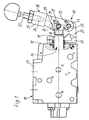
- FIG. 1 shows a view of the invention
- Figure 2 2 shows a side view of the switching element according to FIG. 1
- FIG. 3 a partial section according to III-III in Figure 1 in an enlarged scale 4
- FIG. 1 shows a directional valve 10 with a mechanical one Actuator 11, which on one end face 12 of the Directional control valve 10 is attached.
- the directional valve 10 has a Housing 13 in which a longitudinally movable control slide 14th is slidably guided and with its slide section 15 beyond the end face 12 into the actuating device 11 protrudes.
- the slide section 15 has for this purpose formed by flat flats on both sides Slider end 16 on with a first bolt 17 with a switching element 18 is articulated.
- the switching element 18 is also on this web With the help of a second pin 22 also articulated.
- the switching element 18 has substantially a fork-shaped shape, the two legs 23 and 24 run parallel to one another and in a head part 25 Threaded bore 26 is arranged in which a hand lever 27th is attachable.
- the between the legs 23 and 24 formed gap 28 is chosen so wide that the Switching element 18 with as little friction and play on the Web 21 of the bearing block 19 or on the Slider end 16 is guided.
- the two have Legs 23 and 24 for receiving the first pin 17 each have an elongated hole 29, the two elongated holes are identical to each other.
- Such an elongated hole 29 consists of a guide slot 31, which at its one End is expanded to an assembly recess 32.
- This Mounting recess 32 is formed here as a bore and has a diameter that is larger than the width of the Guide slot 31.
- FIG. 3 now shows a partial section according to III-III in Figure 1 and thus the articulation between the Switching element 18 and the control slide 14, this in is shown on an enlarged scale.
- the first pin 17th between its outer end portions 33 one Center section 34 with a larger diameter.
- This Center section 34 is the first pin 17 in a bore 35 of the spool 14 mounted.
- the diameter of this Bore 35 and thus also the central section 34 noticeably larger than the diameter of the bolt 17 in its end portions 33, with which the bolt 17 in the Guide slots 31 of the switching element 18 is guided.
- the diameter of the central section 34 is so large chosen that a perfect axial securing of Bolt 17 between the legs 23 and 24 in his axial position results.
- the diameter of the Mounting recess 32 chosen so large that the bolt 17 with its center section 34 in the drawn axial position in the switching element 18 can be inserted axially.
- FIG 4 is only a partial section according to IV-IV Articulated connection between switching element 18 and bracket 19 shown.
- the second pin 22 has like the first pin 17 a central section 37 whose diameter is slightly is larger than the diameter of its two end sections 38.
- the central section 37 of the second bolt 22 is in the associated bore 39 stored in the web 21.
- the length of the Center section 39 in the axial direction corresponds to the width of the gap 28 between the legs 23, 24.
- the second bolt 22 with its outer end portions 38 in the Bores 41 of the switching element 18 mounted.
- the diameter of the central section 39 on the second bolt 22 is only slightly larger than the diameter of the end sections 38 and thus the bores 41, so that the second bolt 22 with its larger average diameter due to the smaller one Bore 41 of the switching element 18 can be pressed.
- the switching element 18 must be made of a material a certain elasticity, which is why the switching element 18 preferably made of a glass fiber reinforced plastic will be produced.
- the switching element 18 is so designed that it out without great difficulty Plastic can be injected and no post-processing required.
- the two bolts 17 and 22 are expediently made Made of metal, which is very easy to manufacture because they are thickened by the central portions 34 or 37 have only simple paragraphs; there are no punctures or cross holes required.
- the two bolts 17, 22 are each symmetrical and have end sections with the same Diameter, so that they can be assembled from any position. Out for this reason, the holes 41 and Elongated holes 29 in the two legs 23 and 24 of the same size executed.
- the assembly of the actuating device 11 on the directional control valve 10 is relatively easy to do.
- the switching element 18 After attachment of the bearing block 21 on the housing 13 becomes the switching element 18 with its legs 23 and 24 on the slide end 16 and the web 21 inserted.
- the switching element 18 in brought a situation in which the mounting recesses 32, the are designed as bores, coaxial to the bore 35 in Slider end 16 are. If this is the case, the first can Bolt 17 into the mounting recess 32 from one side be inserted until its central portion 34 in the gap 28 comes to rest. Is the first bolt 17 in the figure 3 shown axial position inserted, so the switching element 18 are pulled up, whereby the end portions 33 of the Bolt 17 in the area of the guide slots 31 in the Slide slots 29.
- the mechanical actuator 11 can be with produce an inexpensive plastic part, the self-locking pin 17, 22 made of metal for a simple, compact and stable construction, hardly any additional Require processing and with its few components meets high security requirements. If on one Directional control valve an electro-hydraulic main actuation is provided, and the mechanical actuator 11 serves only as an emergency actuation, the hand lever 27 omitted, so that less space is required and the inclination disturbing vibrations is reduced. In an emergency it is enough then a simple tool to operate the Switching element 18 in the thread 26 or on a square of the Headboard 25.
Landscapes
- Engineering & Computer Science (AREA)
- General Engineering & Computer Science (AREA)
- Mechanical Engineering (AREA)
- Physics & Mathematics (AREA)
- General Physics & Mathematics (AREA)
- Automation & Control Theory (AREA)
- Mechanically-Actuated Valves (AREA)
- Multiple-Way Valves (AREA)
Applications Claiming Priority (2)
| Application Number | Priority Date | Filing Date | Title |
|---|---|---|---|
| DE2000115298 DE10015298A1 (de) | 2000-03-28 | 2000-03-28 | Wegeventil mit mechanischer Betätigungseinrichtung |
| DE10015298 | 2000-03-28 |
Publications (3)
| Publication Number | Publication Date |
|---|---|
| EP1139194A2 true EP1139194A2 (fr) | 2001-10-04 |
| EP1139194A3 EP1139194A3 (fr) | 2007-01-17 |
| EP1139194B1 EP1139194B1 (fr) | 2008-05-14 |
Family
ID=7636634
Family Applications (1)
| Application Number | Title | Priority Date | Filing Date |
|---|---|---|---|
| EP20000126666 Expired - Lifetime EP1139194B1 (fr) | 2000-03-28 | 2000-12-05 | Distributeur avec dispositif d'actionnement mécanique |
Country Status (2)
| Country | Link |
|---|---|
| EP (1) | EP1139194B1 (fr) |
| DE (2) | DE10015298A1 (fr) |
Cited By (2)
| Publication number | Priority date | Publication date | Assignee | Title |
|---|---|---|---|---|
| CN110792137A (zh) * | 2019-11-22 | 2020-02-14 | 江苏华淼电子科技有限公司 | 一种排水弯管防堵器 |
| FR3136822A1 (fr) * | 2022-06-21 | 2023-12-22 | R Cube Nord | Robinet à fermeture automatique pour la distribution d’un liquide |
Families Citing this family (1)
| Publication number | Priority date | Publication date | Assignee | Title |
|---|---|---|---|---|
| CN106949111B (zh) * | 2017-04-14 | 2019-04-02 | 株洲嘉成科技发展有限公司 | 手动换向阀 |
Citations (1)
| Publication number | Priority date | Publication date | Assignee | Title |
|---|---|---|---|---|
| US3602245A (en) | 1970-02-26 | 1971-08-31 | Abex Corp | Universal detent positioner |
Family Cites Families (3)
| Publication number | Priority date | Publication date | Assignee | Title |
|---|---|---|---|---|
| US2471285A (en) * | 1944-11-08 | 1949-05-24 | David Y Rice | Valve |
| DE3901085C1 (en) * | 1989-01-16 | 1990-03-29 | Gerhard Geiger Gmbh & Co, 7120 Bietigheim-Bissingen, De | Articulated crank |
| DE9108156U1 (de) * | 1991-07-03 | 1991-08-29 | Müller Hydraulik GmbH, 7401 Pliezhausen | Hydraulikventil |
-
2000
- 2000-03-28 DE DE2000115298 patent/DE10015298A1/de not_active Withdrawn
- 2000-12-05 DE DE50015160T patent/DE50015160D1/de not_active Expired - Lifetime
- 2000-12-05 EP EP20000126666 patent/EP1139194B1/fr not_active Expired - Lifetime
Patent Citations (1)
| Publication number | Priority date | Publication date | Assignee | Title |
|---|---|---|---|---|
| US3602245A (en) | 1970-02-26 | 1971-08-31 | Abex Corp | Universal detent positioner |
Cited By (3)
| Publication number | Priority date | Publication date | Assignee | Title |
|---|---|---|---|---|
| CN110792137A (zh) * | 2019-11-22 | 2020-02-14 | 江苏华淼电子科技有限公司 | 一种排水弯管防堵器 |
| FR3136822A1 (fr) * | 2022-06-21 | 2023-12-22 | R Cube Nord | Robinet à fermeture automatique pour la distribution d’un liquide |
| WO2023247571A1 (fr) * | 2022-06-21 | 2023-12-28 | R Cube Nord | Robinet à fermeture automatique pour la distribution d'un liquide |
Also Published As
| Publication number | Publication date |
|---|---|
| EP1139194A3 (fr) | 2007-01-17 |
| EP1139194B1 (fr) | 2008-05-14 |
| DE50015160D1 (de) | 2008-06-26 |
| DE10015298A1 (de) | 2001-10-04 |
Similar Documents
| Publication | Publication Date | Title |
|---|---|---|
| EP2188148B1 (fr) | Dispositif de réglage pour le réglage longitudinal d'un composant de véhicule automobile | |
| DE19919335B4 (de) | Vorrichtung zur lösbaren Verriegelung einer Kopfstütze | |
| EP1588007B1 (fr) | Dispositif de retenue de porte | |
| EP1316465A1 (fr) | Dispositif d'arrêt avec goupilles de blocage rainurées | |
| DE10228580A1 (de) | Träger für ein Fahrzeug | |
| EP3995657B1 (fr) | Arrêt de porte | |
| WO2010043484A1 (fr) | Entraînement à broche muni d’une sécurité antitorsion | |
| EP2668869B1 (fr) | Elément de verrouillage amovible | |
| DE102016110340B3 (de) | Anordnung zum zeitweisen Vorspannen einer Teleskopgabel | |
| DE19940628C1 (de) | Schaltschiene mit daran befestigter Schaltgabel für Kraftfahrzeug-Schaltgetriebe | |
| EP3912866A1 (fr) | Élément ressort pour la fixation d'un module de coussin gonflable à un volant de véhicule ainsi qu'ensemble volant pourvu dudit élément ressort | |
| DE102017214017A1 (de) | Vorrichtung zum Andrücken einer Zahnstange | |
| EP1139194B1 (fr) | Distributeur avec dispositif d'actionnement mécanique | |
| WO2015124129A1 (fr) | Dispositif de commande pour une boîte de vitesses | |
| DE102004033446A1 (de) | Schaltmodul | |
| EP1846633B1 (fr) | Piece intermediaire reglable en longueur, comprenant un mecanisme de blocage du deplacement a effet unidirectionnel | |
| DE10258232B4 (de) | Schaltstange eines Kfz-Schaltgetriebes | |
| DE69605240T2 (de) | In zwei Richtungen wirkende Arretiervorrichtung in einer einstellbaren Steueranlage mit Bowdenzug oder Betätigungsstange | |
| DE9400744U1 (de) | Schließzylinder | |
| EP1900583B1 (fr) | Dispositif à levier pour une soupape de frein à main d'une installation de frein | |
| DE102016214919A1 (de) | Kugelgewindetrieb | |
| EP0767310A2 (fr) | Dispositif de manoeuvre hydraulique | |
| WO2020156614A2 (fr) | Arrêt de porte | |
| DE3007653A1 (de) | Seilfensterheber | |
| EP1667184B1 (fr) | Interrupteur à curseur ou poussoir ou interrupteur combiné à un curseur-poussoir pour un vehicule |
Legal Events
| Date | Code | Title | Description |
|---|---|---|---|
| PUAI | Public reference made under article 153(3) epc to a published international application that has entered the european phase |
Free format text: ORIGINAL CODE: 0009012 |
|
| AK | Designated contracting states |
Kind code of ref document: A2 Designated state(s): AT BE CH CY DE DK ES FI FR GB GR IE IT LI LU MC NL PT SE TR |
|
| AX | Request for extension of the european patent |
Free format text: AL;LT;LV;MK;RO;SI |
|
| PUAL | Search report despatched |
Free format text: ORIGINAL CODE: 0009013 |
|
| AK | Designated contracting states |
Kind code of ref document: A3 Designated state(s): AT BE CH CY DE DK ES FI FR GB GR IE IT LI LU MC NL PT SE TR |
|
| AX | Request for extension of the european patent |
Extension state: AL LT LV MK RO SI |
|
| RIC1 | Information provided on ipc code assigned before grant |
Ipc: F16B 5/00 20060101ALI20061212BHEP Ipc: G05G 1/04 20060101AFI20010521BHEP Ipc: F16B 4/00 20060101ALI20061212BHEP Ipc: F16C 11/04 20060101ALI20061212BHEP Ipc: F16K 31/52 20060101ALI20061212BHEP |
|
| 17P | Request for examination filed |
Effective date: 20070717 |
|
| AKX | Designation fees paid |
Designated state(s): DE FR GB IT SE |
|
| GRAP | Despatch of communication of intention to grant a patent |
Free format text: ORIGINAL CODE: EPIDOSNIGR1 |
|
| GRAS | Grant fee paid |
Free format text: ORIGINAL CODE: EPIDOSNIGR3 |
|
| GRAA | (expected) grant |
Free format text: ORIGINAL CODE: 0009210 |
|
| AK | Designated contracting states |
Kind code of ref document: B1 Designated state(s): DE FR GB IT SE |
|
| REG | Reference to a national code |
Ref country code: GB Ref legal event code: FG4D Free format text: NOT ENGLISH |
|
| REF | Corresponds to: |
Ref document number: 50015160 Country of ref document: DE Date of ref document: 20080626 Kind code of ref document: P |
|
| REG | Reference to a national code |
Ref country code: SE Ref legal event code: TRGR |
|
| PLBE | No opposition filed within time limit |
Free format text: ORIGINAL CODE: 0009261 |
|
| STAA | Information on the status of an ep patent application or granted ep patent |
Free format text: STATUS: NO OPPOSITION FILED WITHIN TIME LIMIT |
|
| 26N | No opposition filed |
Effective date: 20090217 |
|
| REG | Reference to a national code |
Ref country code: FR Ref legal event code: ST Effective date: 20090831 |
|
| PG25 | Lapsed in a contracting state [announced via postgrant information from national office to epo] |
Ref country code: FR Free format text: LAPSE BECAUSE OF NON-PAYMENT OF DUE FEES Effective date: 20081231 |
|
| PGFP | Annual fee paid to national office [announced via postgrant information from national office to epo] |
Ref country code: GB Payment date: 20101221 Year of fee payment: 11 Ref country code: SE Payment date: 20101221 Year of fee payment: 11 |
|
| PGFP | Annual fee paid to national office [announced via postgrant information from national office to epo] |
Ref country code: IT Payment date: 20101227 Year of fee payment: 11 |
|
| REG | Reference to a national code |
Ref country code: DE Ref legal event code: R084 Ref document number: 50015160 Country of ref document: DE Effective date: 20110908 |
|
| REG | Reference to a national code |
Ref country code: SE Ref legal event code: EUG |
|
| GBPC | Gb: european patent ceased through non-payment of renewal fee |
Effective date: 20111205 |
|
| PG25 | Lapsed in a contracting state [announced via postgrant information from national office to epo] |
Ref country code: SE Free format text: LAPSE BECAUSE OF NON-PAYMENT OF DUE FEES Effective date: 20111206 Ref country code: GB Free format text: LAPSE BECAUSE OF NON-PAYMENT OF DUE FEES Effective date: 20111205 |
|
| PGFP | Annual fee paid to national office [announced via postgrant information from national office to epo] |
Ref country code: DE Payment date: 20130225 Year of fee payment: 13 |
|
| PG25 | Lapsed in a contracting state [announced via postgrant information from national office to epo] |
Ref country code: IT Free format text: LAPSE BECAUSE OF NON-PAYMENT OF DUE FEES Effective date: 20121205 |
|
| REG | Reference to a national code |
Ref country code: DE Ref legal event code: R119 Ref document number: 50015160 Country of ref document: DE |
|
| REG | Reference to a national code |
Ref country code: DE Ref legal event code: R119 Ref document number: 50015160 Country of ref document: DE Effective date: 20140701 |
|
| PG25 | Lapsed in a contracting state [announced via postgrant information from national office to epo] |
Ref country code: DE Free format text: LAPSE BECAUSE OF NON-PAYMENT OF DUE FEES Effective date: 20140701 |