EP1139351A2 - Vorrichtung zum Erzeugen von Drilleitern durch Verröbeln von Isolierten Profildrähten, inbesondere rechteckigen Querschnitts - Google Patents
Vorrichtung zum Erzeugen von Drilleitern durch Verröbeln von Isolierten Profildrähten, inbesondere rechteckigen Querschnitts Download PDFInfo
- Publication number
- EP1139351A2 EP1139351A2 EP01107682A EP01107682A EP1139351A2 EP 1139351 A2 EP1139351 A2 EP 1139351A2 EP 01107682 A EP01107682 A EP 01107682A EP 01107682 A EP01107682 A EP 01107682A EP 1139351 A2 EP1139351 A2 EP 1139351A2
- Authority
- EP
- European Patent Office
- Prior art keywords
- profile wires
- wires
- profile
- pushers
- another
- Prior art date
- Legal status (The legal status is an assumption and is not a legal conclusion. Google has not performed a legal analysis and makes no representation as to the accuracy of the status listed.)
- Withdrawn
Links
Images


Classifications
-
- H—ELECTRICITY
- H01—ELECTRIC ELEMENTS
- H01B—CABLES; CONDUCTORS; INSULATORS; SELECTION OF MATERIALS FOR THEIR CONDUCTIVE, INSULATING OR DIELECTRIC PROPERTIES
- H01B13/00—Apparatus or processes specially adapted for manufacturing conductors or cables
- H01B13/02—Stranding-up
- H01B13/0278—Stranding machines comprising a transposing mechanism
Definitions
- the invention relates to a device for producing multicore twisted pairs by rubbing insulated profile wires, especially rectangular cross-section, with a guide for those conveyed in at least two parallel stacks Profile wires made of lateral parallel guide surfaces and at 90 ° to them offset pushers, one per stack, is formed, the two Pusher diametrically opposed and intermittently parallel to each other are displaceable, and with opposite to the longitudinal extension of the wire conductor to the opposite Shifting a profile wire from one to the adjacent one Stacking slides movable under this profile wire, the other in the other Diagonals as the pushers are mounted opposite each other, and with a control for synchronizing the cyclical actuation of the drives for moving the pushers and the slide.
- GB-PS 969 086 is a device for producing a composite known electrical conductor, in which the isolated individual conductors are rectangular Cross-section in parallel adjacent stacks of a rocking tool run through. On the circumference of that formed from the stacked profile wires Stranges attack sliders, which are the top and bottom, respectively Move the profile ladder to the adjacent stack by cranking it. This process, which enables the twisting of angular profile conductors, is called one "robs", and the tool is, according to the inventor Röbel, a Röbel tool designated.
- the well-known Röbel tool has two sliders for moving of the upper and lower profile wire on the adjacent stack further two Pusher, each one stack of the individual conductors up or down to press. After completing this pushing process, the slides grip to move of the profile wires in the manner described.
- the invention is therefore based on the task, the stress of both Röbel tool as well as the surface of the partial conductor detected by this to reduce significantly.
- FIG. 5 shows the rear view of a twisting head 11 that rattles profile wires.
- the guide 2 is provided for the formation of the twisted conductor 5 Profile wires 1 on.
- Four gears 12 are provided in the drill head, on their output in each case a pressure plate 13 or sliding plate 14 are arranged.
- On the Thrust washers 13 and the sliding washers 14 are eccentrically three each a cylindrical jacket having contact disks 15 overhung and freely supported. This results in the following possibility: While the pressure disc is rotating 13 and the sliding disc 14 are their three contact discs in succession 15 due to their eccentric position on the pusher or sliding disks advanced three times and withdrawn three times.
- the thrust washers 13 arranged so that the contact disks 15 in front of them with grasp one of the stacks 3 and 4 of the stranded conductor 5 and cover them accordingly advance the arrow directions 6 of FIG. 2.
- the sliding washers 14 are provided next to the highest and lowest of the profile wires, that when pushing their contact discs 15 the top and bottom the profile wires 1 in the direction of arrows 7 of Figure 3 by a full width of the profile wires be moved so that they are above or below the neighboring ones Stack to be pushed.
- the two sliding disks 14 are operated and push their contact disks 15 forward. Here they meet the flanks of the extreme, each freed profile wires and move them on or under the adjacent one of the stacks 3, 4.
- the contact disks also lie here 15 each against one of the base surfaces of the profile wires 1, here their Flanks, and arrange them to the opposite one by cranking them Stack too. If there is any risk of damaging the insulation, so there is definitely the possibility, not shown in the exemplary embodiment, the jacket of the contact disks 15 with a more or less elastic cover layer.
- the drive of the gear 12 is arbitrary since the drill head 11 is not rotating interpretable; however, as is known, a slowly rotating ring gear 16 be provided, the drive of the gearbox via gears 17 as countershaft 12 causes.
- FIG. 6 shows an enlarged illustration of a comparable representation against a flank of the conductor 5 seen embodiment given. Comparable parts are adopted with the reference numbers known from FIG. 5.
- Gear 12 is shown in the cutout only one. Your drive shafts will be 20 driven via shafts, not shown here.
- the gear blocks also not shown here, via slots adjustable, clamped on the drill head 11, while the fine adjustment and Relief of these elongated holes from longitudinal forces with counter-adjustable screws he follows.
- pressure or sliding disks 13 or 14 held axially displaceable by a telescopic extension 21 and by means of Springs must be biased against stops, so that the bearing forces of the flanges can be determined by contact disks.
- the transmission outputs with thrust washers 13 or sliding washers 14 equipped which are each provided with contact disks 15, the flying and easily stored freely so that when contacting Flanks or base areas of rectangular profile wires 1 the contact disks 15 can accumulate and on the contacted flanks or base areas of profile wires 1 of the future conductor 5 sliding friction is avoided and the freely stored contact disks 15 run on these surfaces.
- the contact disks 15 can be made of separate, for example partially elastic, Consist of material or receive a coat of such materials in order to avoid any wear and damage, for example. The insulation of the Avoid profile wires 1.
- the contact disk 15 of the pressure disk 13 to push the top profile wire 1 of the stack 4 over the stack 3 can After this contact disc 15 has continued to run and has completely exited from the cross section of the twist conductor 5, the thrust washers 13 can be made in this way are actuated that their contact discs 15 on the upper wire of the Place stack 3 and the entire stack 3 while lifting the Move stack 4 so far that the offset profile wire is offset now the cycle is closed and again the upper profile wire of the Stack 4 is free, as this also applies to the lower profile wire of stack 2. So simple mechanical control via the common drive the respective effects of the contact disks 15 are caused.
- the essential further developments shown in FIG. 6 are the low-friction Guiding the wire conductor 5 through horizontal guide rollers 18 and vertical Guide rollers 19.
- the drive of the drive shaft 20 of the transmission 12 can by means of arbitrarily coupled drive shafts.
- the smooth storage of the Sliding disc 14 takes place via a tubular extension 21 of the same, which means four roller bearing 23 is mounted in a hollow cylindrical connector 22, which on Housing of the transmission 12 is attached.
- the drill head 11 has bridges 24 to which, adjustable and can be countered, with Support the housing of the gearbox 12 connected screws. Tightening takes place via slots 26 penetrating screws 27 after adjustment the effective height by means of the screws 25.
- Sliding discs 14 is dispensed with and simple, which can be advanced in the axial direction Tappets can be used. These plungers are at their free ends equipped with smooth-running panes, so that their insulating layer here too is practically not burdened.
- An upper plunger 28 is provided around the upper profile wire in the direction of the arrow 7 push and crank while opposing a pre-section this profile wire repels an upper one against this plunger and thus one desirable short cranking area.
- the same arrangement is intended for cranking at the bottom, to simplify the presentation however not shown in the drawings.
Landscapes
- Engineering & Computer Science (AREA)
- Manufacturing & Machinery (AREA)
- Manufacturing Of Electrical Connectors (AREA)
- Wire Processing (AREA)
- Ropes Or Cables (AREA)
- Processes Specially Adapted For Manufacturing Cables (AREA)
Abstract
Description
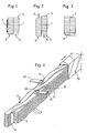
Es zeigen hierbei:
- Fign. 1 - 3
- schematisch unterschiedliche Querschnitte durch einen Drilleiter mit in zwei parallelen Stapeln angeordneten Profildrähten rechteckigen Querschnitts,
- Fig. 4
- schematisch einen Abschnitt eines geröbelten Drilleiters,
- Fig. 5
- eine Rückansicht eines Ausführungsbeispieles eines erfindungsgemäßen Drillkopfes, und
- Fig. 6
- eine entsprechende Darstellung eines vergrößerten Ausschnittes eines in der Seitenansicht dargestellten weiteren Ausführungsbeispiels.
- 1
- Profildrähte
- 2
- Führung
- 3
- Stapel
- 4
- Stapel
- 5
- Drilleiter
- 6
- Pfeilrichtung
- 7
- Pfeilrichtung
- 8
- Kröpfungsbereich
- 9
- Papier
- 10
- Isolierschicht
- 11
- Drillkopf
- 12
- Getriebe
- 13
- Drückscheibe
- 14
- Schiebescheibe
- 15
- Kontaktscheiben
- 16
- Zahnkranz
- 17
- Zahnräder
- 18
- Führungswalze
- 19
- Führungswalze
- 20
- Antriebswelle
- 21
- Ansatz
- 22
- Stutzen
- 23
- Walzlager
- 24
- Brücke
- 25
- Schraube
- 26
- Langloch
- 27
- Schraube
- 28
- Stößel oder
- 29
- Gegenstößel
- 30
- Rolle
- 31
- Rolle
Claims (9)
- Vorrichtung zum Erzeugen von vieladrigen Drilleitern (5) zum Verröbeln von isolierten Profildrähten (1), insbesondere rechteckigen Querschnitts, mit einer Führung (2, 18, 19) für die in mindestens zwei parallelen Stapeln geförderten Profildrähte (1), die aus seitlichen Parallelführungsflächen und um 90° zu diesen versetzten Drückern, und zwar einem je Stapel, gebildet ist, wobei die beiden Drücker einander diametral gegenüberliegen und taktweise gegeneinander parallel verschiebbar sind, und mit quer zur Längserstreckung des Drilleiters (5) zur gegenläufigen Verschiebung je eines Profildrahtes (1) von einem auf den benachbarten Stapel (3, 4) unter Kröpfung dieses Profildrahtes (1) bewegbaren Schiebern, die in der anderen Diagonalen wie die Drücker einander gegenüberliegend gelagert sind, und mit einer Steuerung zur Synchronisierung der taktweisen Betätigung der Antriebe für die Verschiebung der Drücker sowie der Schieber,
dadurch gekennzeichnet, daß die aktiven, auf die Profildrähte (1) einwirkenden Teile des Röbelwerkzeuges mit auf Auflageflächen der Profildrähte laufenden und die aktiven Teile des Röbelwerkzeuges umlaufenden Zwischengliedern wie Ketten, Kunststoffstränge, Rollen (30, 31), Kontaktscheiben (15) oder dergleichen ausgestattet sind. - Vorrichtung nach Anspruch 1,
dadurch gekennzeichnet, daß als aktive umlaufende Teile des Röbelwerkzeuges rotierende Scheiben (13, 14) vorgesehen sind, die mit exzentrisch angeordneten, leichtläufig freigängig gelagerten Kontaktscheiben (15) ausgestattet sind, deren Umfang sich beim Verschieben der Profildrähte (1) oder Stapeln (3, 4) solcher Profildrähte auf Flanken bzw. Grundflächen dieser Profildrähte abwälzen. - Vorrichtung nach Anspruch 2,
dadurch gekennzeichnet, daß Mantelflächen der Kontaktscheiben (15) mit einem elastischen Material beschichtet sind. - Vorrichtung nach einem der Ansprüche 1 bis 3,
dadurch gekennzeichnet, daß die freien Enden von als Stößel ausgebildeten Drückern und/oder Schiebern mit leichtgängig gelagerten, auf Grundflächen von Profildrähten ablaufender Rollen (30, 31) ausgestattet sind. - Vorrichtung nach einem der Ansprüche 1 bis 4,
dadurch gekennzeichnet, daß für je einen Drücker oder Schieber ein Getriebe (12) vorgesehen ist, dessen Ausgang mit je einer Scheibe (13, 14) versehen ist, welche exzentrisch angeordnete Achsen zur Aufnahme von leichtgängig frei gelagerten Kontaktscheiben (15) aufweist. - Vorrichtung nach Anspruch 5,
dadurch gekennzeichnet, daß jede Scheibe (13, 14) mit einer Kontaktscheibe (15) ausgestattet ist. - Vorrichtung nach Anspruch 5,
dadurch gekennzeichnet, daß jede Scheibe (13, 14) mit mehr als einer Kontaktscheibe (15) ausgestattet ist. - Vorrichtung nach einem der Ansprüche 1 bis 7,
dadurch gekennzeichnet, daß die Antriebsachsen der Getriebe (12) miteinander gekoppelt sind. - Vorrichtung nach einem der Ansprüche 1 bis 8,
gekennzeichnet durch
den zu kröpfenden Profildraht (1) abstützende Gegenstößel (29) bzw. Gegenschieber.
Applications Claiming Priority (4)
| Application Number | Priority Date | Filing Date | Title |
|---|---|---|---|
| DE10015134 | 2000-03-29 | ||
| DE10015134 | 2000-03-29 | ||
| DE10026455 | 2000-05-27 | ||
| DE10026455A DE10026455A1 (de) | 2000-03-29 | 2000-05-27 | Vorrichtung zum Erzeugen von Drilleitern durch Verröbeln von von isolierten Profildrähten, insbesondere rechteckigen Querschnitts |
Publications (2)
| Publication Number | Publication Date |
|---|---|
| EP1139351A2 true EP1139351A2 (de) | 2001-10-04 |
| EP1139351A3 EP1139351A3 (de) | 2002-02-20 |
Family
ID=26005042
Family Applications (1)
| Application Number | Title | Priority Date | Filing Date |
|---|---|---|---|
| EP01107682A Withdrawn EP1139351A3 (de) | 2000-03-29 | 2001-03-28 | Vorrichtung zum Erzeugen von Drilleitern durch Verröbeln von Isolierten Profildrähten, inbesondere rechteckigen Querschnitts |
Country Status (1)
| Country | Link |
|---|---|
| EP (1) | EP1139351A3 (de) |
Cited By (3)
| Publication number | Priority date | Publication date | Assignee | Title |
|---|---|---|---|---|
| CN114898952A (zh) * | 2022-05-09 | 2022-08-12 | 江西赣电电气有限公司 | 一种绝缘纸筒滚圆机 |
| CN115274206A (zh) * | 2022-07-25 | 2022-11-01 | 江苏中容电气有限公司 | 一种带预制油道组合换位导线结构 |
| CN120913960A (zh) * | 2025-10-09 | 2025-11-07 | 苏州荣盛电工材料有限公司 | 一种用于换位导线加工系统及使用方法 |
Family Cites Families (3)
| Publication number | Priority date | Publication date | Assignee | Title |
|---|---|---|---|---|
| NL236589A (de) * | 1958-02-27 | |||
| US3154112A (en) * | 1961-11-15 | 1964-10-27 | Gen Electric | Strand transposing mechanism |
| IT1285274B1 (it) * | 1996-02-28 | 1998-06-03 | Proteco Di Cappa Rasone Edda & | Testa traspositrice per la formazione di conduttori ctc. |
-
2001
- 2001-03-28 EP EP01107682A patent/EP1139351A3/de not_active Withdrawn
Cited By (4)
| Publication number | Priority date | Publication date | Assignee | Title |
|---|---|---|---|---|
| CN114898952A (zh) * | 2022-05-09 | 2022-08-12 | 江西赣电电气有限公司 | 一种绝缘纸筒滚圆机 |
| CN114898952B (zh) * | 2022-05-09 | 2023-04-25 | 江西赣电电气有限公司 | 一种绝缘纸筒滚圆机 |
| CN115274206A (zh) * | 2022-07-25 | 2022-11-01 | 江苏中容电气有限公司 | 一种带预制油道组合换位导线结构 |
| CN120913960A (zh) * | 2025-10-09 | 2025-11-07 | 苏州荣盛电工材料有限公司 | 一种用于换位导线加工系统及使用方法 |
Also Published As
| Publication number | Publication date |
|---|---|
| EP1139351A3 (de) | 2002-02-20 |
Similar Documents
| Publication | Publication Date | Title |
|---|---|---|
| DE3603121C2 (de) | ||
| EP0639882B1 (de) | Nutverschlussanordnung | |
| EP2891166B1 (de) | Kraftspeicher für einen laststufenschalter | |
| DE2829433C2 (de) | Schraubengetriebe | |
| DE4407537A1 (de) | Linearantrieb | |
| DE3540652A1 (de) | Elektrischer schraubendreher | |
| EP1162633B1 (de) | Verfahren und Vorrichtung zur Herstellung von Drilleitern | |
| DE68903853T2 (de) | Verfahren und Einrichtung zum Einschieben einer Vielzahl von Phasenisolatoren in die Ständernuten einer dynamoelektrischen Maschine. | |
| WO2013174567A1 (de) | Kraftspeicher für einen laststufenschalter | |
| DE2814510A1 (de) | Pruefvorrichtung fuer schaltungsplatten | |
| WO2018096151A1 (de) | Dämpfungs- und federanordnung und verfahren zu deren herstellung | |
| EP0790098A1 (de) | Linearantrieb | |
| EP1139351A2 (de) | Vorrichtung zum Erzeugen von Drilleitern durch Verröbeln von Isolierten Profildrähten, inbesondere rechteckigen Querschnitts | |
| EP0408832A2 (de) | Vorrichtung zum Erzeugen von Drilleitern | |
| DE19726398C2 (de) | Antriebssystem für Lamellen | |
| DE2161667C3 (de) | Verfahren zur Herstellung von verseilten Drahterzeugnissen | |
| DE10026455A1 (de) | Vorrichtung zum Erzeugen von Drilleitern durch Verröbeln von von isolierten Profildrähten, insbesondere rechteckigen Querschnitts | |
| EP0932241B1 (de) | Verfahren zur Herstellung von Leiterstäben | |
| DE102018003643B3 (de) | Kurven-gesteuertes Schrittgetriebe | |
| DE7626052U1 (de) | Getriebe mit einem flexiblen uebertragungsglied | |
| EP0089074B1 (de) | Anordnung zum Trennen einzelner Leiter voneinander in einem Flachbandkabel | |
| DE69423453T2 (de) | Vorrichtung für die Änderung der Abstände von ausgewählten Drähten in einer seitlichen Anordnung von Drähten | |
| DE3527210C2 (de) | ||
| DE10392948B4 (de) | Drehbarer Antrieb und Schaltmechanismus mit diesem drehbaren Antrieb | |
| DE4129109A1 (de) | Einrichtung zur axialverschiebung eines bauteils |
Legal Events
| Date | Code | Title | Description |
|---|---|---|---|
| PUAI | Public reference made under article 153(3) epc to a published international application that has entered the european phase |
Free format text: ORIGINAL CODE: 0009012 |
|
| AK | Designated contracting states |
Kind code of ref document: A2 Designated state(s): AT BE CH CY DE DK ES FI FR GB GR IE IT LI LU MC NL PT SE TR |
|
| AX | Request for extension of the european patent |
Free format text: AL;LT;LV;MK;RO;SI |
|
| PUAL | Search report despatched |
Free format text: ORIGINAL CODE: 0009013 |
|
| AK | Designated contracting states |
Kind code of ref document: A3 Designated state(s): AT BE CH CY DE DK ES FI FR GB GR IE IT LI LU MC NL PT SE TR |
|
| AX | Request for extension of the european patent |
Free format text: AL;LT;LV;MK;RO;SI |
|
| AKX | Designation fees paid | ||
| REG | Reference to a national code |
Ref country code: DE Ref legal event code: 8566 |
|
| STAA | Information on the status of an ep patent application or granted ep patent |
Free format text: STATUS: THE APPLICATION IS DEEMED TO BE WITHDRAWN |
|
| 18D | Application deemed to be withdrawn |
Effective date: 20020821 |