EP1139578A2 - CDMA Demodulationsschaltung und CDMA Demodulationsverfahren - Google Patents
CDMA Demodulationsschaltung und CDMA Demodulationsverfahren Download PDFInfo
- Publication number
- EP1139578A2 EP1139578A2 EP01107452A EP01107452A EP1139578A2 EP 1139578 A2 EP1139578 A2 EP 1139578A2 EP 01107452 A EP01107452 A EP 01107452A EP 01107452 A EP01107452 A EP 01107452A EP 1139578 A2 EP1139578 A2 EP 1139578A2
- Authority
- EP
- European Patent Office
- Prior art keywords
- reception level
- path
- fingers
- cycle
- drop
- Prior art date
- Legal status (The legal status is an assumption and is not a legal conclusion. Google has not performed a legal analysis and makes no representation as to the accuracy of the status listed.)
- Granted
Links
Images




Classifications
-
- H—ELECTRICITY
- H04—ELECTRIC COMMUNICATION TECHNIQUE
- H04B—TRANSMISSION
- H04B1/00—Details of transmission systems, not covered by a single one of groups H04B3/00 - H04B13/00; Details of transmission systems not characterised by the medium used for transmission
- H04B1/69—Spread spectrum techniques
- H04B1/707—Spread spectrum techniques using direct sequence modulation
- H04B1/7097—Interference-related aspects
- H04B1/711—Interference-related aspects the interference being multi-path interference
- H04B1/7113—Determination of path profile
-
- H—ELECTRICITY
- H04—ELECTRIC COMMUNICATION TECHNIQUE
- H04B—TRANSMISSION
- H04B1/00—Details of transmission systems, not covered by a single one of groups H04B3/00 - H04B13/00; Details of transmission systems not characterised by the medium used for transmission
- H04B1/69—Spread spectrum techniques
- H04B1/707—Spread spectrum techniques using direct sequence modulation
- H04B1/7097—Interference-related aspects
- H04B1/711—Interference-related aspects the interference being multi-path interference
- H04B1/7115—Constructive combining of multi-path signals, i.e. RAKE receivers
- H04B1/7117—Selection, re-selection, allocation or re-allocation of paths to fingers, e.g. timing offset control of allocated fingers
Definitions
- the present invention relates to a CDMA demodulation circuit and a CDMA demodulation method, and more particularly to the CDMA demodulation circuit and the CDMA demodulation method used for mobile communication devices.
- the technique disclosed in the document 1 is to determine a cycle for integrating correlation power according to a length of an actual fading cycle.
- the technique disclosed in the document 2 is to measure a delay profile of a baseband signal while changing a measuring time for measuring the delay profile, and to select a desired number of scattered waves based on the measured delay profile to assign respective reception timing to the corresponding de-spreading circuit.
- the technique disclosed in the document 3 is to provide delay profile calculating means for applying moving average for a moving average period corresponding to a timing fluctuation in a selected path, allowing path movement to follow a rapid timing fluctuation in the selected path by decreasing the moving average period when the timing fluctuation is big and by increasing it when the fluctuation is small.
- the technique disclosed in the document 4 is to search a reception path timing by means of data received at a high reception level and to perform correlation and combination according to the reception paths.
- the technique disclosed in the document 5 comprises a searcher unit that obtains sequences of measurements from a multipath profile, the searcher unit having a predetermined timing resolution that separates adjacent measurements within the sequence. The technique reads the sequences of measurements, derives timing offsets having resolutions higher than the predetermined timing resolution of the searcher unit, and assigns finger processing elements to the best candidate paths using the timing offsets.
- the technique disclosed in the document 1 in particular measures the length of the actual fading cycle to determine the most suitable cycle for that length to integrate the correlation power.
- the present invention measures times at which the level drops due to actual fading and, from these drop times, estimates a time at which the level drops due to the next fading. Then, it controls assignment of path timing to a fingers portion before the level drops.
- Such a technique for estimating the time at which the level drops due to fading is not disclosed in any of the above referred documents from 2 to 5.
- the object of the invention consists in providing a CDMA demodulation circuit and method which are capable of maintaining good reception quality even in a mobile environment by estimating a time at which the level drops due to fading and by controlling assignment of path timing to a fingers portion before the level actually drops.
- the present invention is the CDMA demodulation circuit comprising delay profile calculating means for calculating delay profiles of received signals; path assigning means for assigning path locations to a plurality of fingers based on the calculation result obtained in the delay profile calculating means; the plurality of fingers to which the path locations are assigned by the path assigning means, the fingers de-spreading the assigned paths; and rake combining means for combining output of the plurality of fingers.
- This demodulation circuit is characterized by comprising reception controlling means that estimates a drop cycle of the reception level from the reception level combined by the rake combining means and that reduces degradation in receiving characteristics using the estimation result.
- another invention according to the present invention is the demodulation method for the CDMA demodulation circuit comprising the delay profile calculating means for calculating delay profiles of received signals; the path assigning means for assigning path locations to the plurality of fingers based on the calculation result obtained in the delay profile calculation means; the plurality of fingers to which the path locations are assigned by the path assigning means, the fingers de-spreading the assigned paths; and the rake combining means for combining output of the plurality of fingers.
- This demodulation method is characterized by comprising a first step of estimating the drop cycle of the reception level from the reception level combined by the rake combining means to reduce degradation in receiving characteristics using the estimation result.
- the present invention and the other invention according to the present invention make it possible to maintain good reception quality even in a mobile environment by estimating the time at which the level drops due to fading, and by controlling the assignment of path timing to the fingers portion before the level actually drops.
- a fingers portion 3 performs de-spreading, and a rake combining portion 4 determines a reception level.
- a fading pitch estimation portion 6 estimates a drop cycle of the reception level from the obtained reception level, and a finger path assignment control portion 7 uses the result to control a finger path assignment portion 2. In this manner, good receiving characteristics can be achieved even in a mobile communication environment by monitoring the reception level and avoiding use of data in a poor receiving condition to update path locations for assigning to the fingers.
- FIG. 1 is a block diagram of a first embodiment of the CDMA demodulation circuit according to the present invention.
- the CDMA demodulation circuit is configured to comprise a delay profile calculation portion 1, the finger path assignment portion 2, the fingers portion 3, the rake combining portion 4, a received data processing portion 5, the fading pitch estimation portion 6, and the finger path assignment control portion 7.
- FIG. 2 is a block diagram of an example of the delay profile calculation portion 1.
- the delay profile calculation portion 1 is configured with a phase shift controller for delay profiles 11, a diffusion code generator 12, a correlator 13, an integrator 14, a switch 15, and memory 16.
- the diffusion code generator 12 In the delay profile calculation portion 1, the diffusion code generator 12 generates diffusion codes shifted by a phase shift amount, and the correlator 13 calculates correlation power of I components (Ich) and Q components (Qch) that were quadrature-detected and demodulated.
- the integrator 14 integrates the correlation power, and the phase shift controller for delay profiles 11 periodically updates the phase shift amount.
- the switch 15 switches connections between the integrator 14 and the memory 16 according to the phase shift amount to periodically store delay profile data in the memory 16.
- the delay profile data stored in the memory 16 is peak-searched by the finger path assignment portion 2 and assigned, in the higher power-correlation value order, to the fingers portion 3 as the path locations for assigning to the fingers.
- each finger de-spreads the assigned path, and its output is rake-combined by the rake combining portion 4. Then, signals combined by the rake combining portion 4 are demodulated in the received data processing portion 5 and are also input to the fading pitch estimation portion 6.
- a fading pitch is estimated by monitoring fluctuation in the input reception level. Then, according to the result, the finger path assignment control portion 7 controls the finger path assignment portion 2.
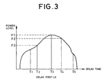
- FIG. 3 is a diagram showing an example of characteristics of a delay profile. As shown in FIG. 3, first the path location (delay time ⁇ 3) with the highest power correlation value (power level P1) is assigned to a first finger, then the path location (delay time ⁇ 4) with the second highest power correlation value (power level P2) is assigned to a second finger, and the path location (delay time ⁇ 2) with the third highest power correlation value (power level P3) is assigned to a third finger. This is an example where there are three fingers.
- FIG. 4 is a diagram of reception level - to - moving distance characteristics, which indicates fast fading of radio waves in mobile communication.
- radio waves forms standing waves with being reflected and diffracted by buildings etc. around them.
- intense fading over a range of more than several tens of dB occurs.
- the minimum value among the intervals between occurrences of intense level attenuation (referred to as a fading pitch (Ti)) is equal to an inverse number of Doppler frequency.
- the fading pitch estimation portion 6 estimates this fading pitch Ti by monitoring fluctuation in the reception level and predicts the time of a next intense level attenuation.
- FIG. 5 is a flow chart showing the operation for estimating the fading pitch Ti in the fading pitch estimation portion 6.
- the fading pitch estimation portion 6 first measures the reception level (S1). Next, it determines whether or not the reception level is equal to or below the threshold H (H is a positive, real number) (S2). If the level is equal to or below the threshold H (YES at S2), the operation returns to the step S1. On the other hand, if the level is above the threshold H (NO at S2), it determines whether of not the reception level measured last time is equal to or below the threshold H (S3). Then, if the level is above the threshold H (NO at S3), the operation returns to the step S1.
- H is a positive, real number
- the level is equal to or below the threshold H (YES at S3), it detects a time at which a minimum level was measured within a time period in which the reception level equal to or below the threshold H has been successively measured (S4). Next, it calculates a time difference (fading pitch Ti) between the last detected time at which a minimum reception level was measured and the second last detected time at which a minimum reception level was measured (S5).
- a time difference fading pitch Ti
- the operation determines whether or not the absolute value of the difference between the last calculated time difference Ti and the currently calculated time difference Ti is equal to or below P (P is a positive, real number) (S6).
- P is a positive, real number
- the reason to determine whether or not the absolute value is equal to or below P is that such a case is out of the object of the present invention that the absolute value of the difference between the last calculated time difference Ti and the currently calculated time difference Ti exceeds P. That is, estimation of the fading pitch Ti would be difficult if the fading pitch Ti exceeds a certain time length. If the absolute value is above P at the step S6 (NO at S6), the operation returns to the step S1.
- the operation determines whether or not absolute values equal to or below P have continued for Q times (Q is a positive integer) (S7). If they have not continued for Q times at the step S7 (NO at S7), the operation returns to the step S1. On the other hand, if they have continued for Q times at the step S7 (YES at S7), it averages those time differences Tis (S8). This average of the time differences Ti is the estimation of the fading pitch Ti.
- a backward alignment guard level: N (N is a positive integer) and a forward alignment guard level: M (Mis a positive integer) are set to prevent flapping in updating the path locations for assigning to the fingers.
- the guard levels allow that only the path locations detected successively for N times by peak search processing are assigned to the fingers. Further, once the path locations are assigned to the fingers, they are not excluded from paths for assigning to the fingers unless it is determined successively for M times that they are not detected.
- the peak-searched and detected path locations that meet these conditions are input to the fingers portion 3 as the paths for assigning to the fingers.
- FIG. 6 is a flow chart showing the operation of the finger path assignment control portion 7.
- this flow chart also includes the operation in the rake combining portion 4 and the fading pitch estimating portion 6.
- each finger de-spreads an assigned path in the fingers portion 3, and the output is rake-combined by the rake combining portion 4 (S11).
- the signals combined by the rake combining portion 4 are demodulated by the received data processing portion 5 and are also inputted to the fading pitch estimation portion 6.
- the fading pitch is estimated by monitoring fluctuation in the input reception level (S12).
- the finger path assignment control portion 7 controls the finger path assignment portion 2 (S13, S14).
- the fading pitch estimation portion 6 estimates the drop cycle of the reception level in terms of Doppler frequency by monitoring fluctuation in the reception level (S12). If the finger path assignment control portion 7 determines from the estimation result that a drop of the reception level due to fading will be intense (YES at S13), it controls the finger path assignment portion 2 to increase its forward and backward alignment guard levels before the reception level drops (S14). That is, it controls the finger path assignment portion 2 to maintain the finger path assignment result obtained from data with less fading influence and to reduce tendency to employ the finger path assignment result to be obtained from data with significant fading influence.
- the finger path assignment control portion 7 controls the guard levels of the finger path assignment portion 2 before the reception level drops by increasing tendency to maintain, during the reception level are suffered from intense level attenuation (see L2 in FIG. 4), the finger path assignment result obtained from the data received just before the level attenuation (see L1 in FIG. 4). This makes it possible to reduce fading influence and to maintain good reception quality.
- FIG. 7 is a block diagram of the second embodiment
- FIG. 8 is a flow chart showing an operation of the second embodiment. Steps from S11 to S13 in the operation of controlling finger path assignment are same as those in the first embodiment, thereby not shown nor described about their operation.
- output of the finger path assignment control portion 7 is inputted to the delay profile calculation portion 1.
- the finger path assignment control portion 7 controls the delay profile calculation portion 1 to increase the number of averaging frame for the delay profile calculation (S21). For example, the delay profile calculation portion 1 that might create and average delay profiles per three frames would be changed to create and average delay profiles per five frames.
- the increased number of averaging frame for delay profiles prevents delay profiles from being calculated only with received data suffered from intense fading, and reduces errors in path search.
- the third embodiment stops updating the finger path assignment in the finger path assignment control portion 7 instead of controlling the guard levels and the number of averaging frame for delay profile calculation. This makes it possible to produce a similar effect of reducing degradation in the receiving characteristics due to fading, as well as to reduce power consumption.
- FIG. 9 is a flow chart showing the operation of the third embodiment. Steps from S11 to S13 in the operation of the finger path assignment are same as those in the first embodiment, thereby not shown nor described about their operation.
- the configuration of the third embodiment is also same as that of the first embodiment (see FIG. 1).
- the finger path assignment control portion 7 stops updating the finger path assignment in the finger path assignment portion 2 (S31). Then, it makes the finger path assignment portion 2 to maintain the last result (finger paths)(S32).
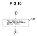
- FIG. 10 is a flow chart showing operation of the fourth embodiment. Again, the steps from S11 to S13 in FIG. 6 will be similarly used in the embodiments below.
- the finger assignment control portion 7 resets its control (S41) and restart from the first process (see S11 in FIG. 6).
- FIG. 8 The flow chart of FIG. 8 will be used for an operation of the sixth embodiment. That is, after the number of averaging frame for delay profiles is increased (S21), the fading pitch estimation portion 6 is again made to estimate the fading pitch (S13). Description about further operation will be omitted, as it has been given above.
- the present invention makes it possible to maintain good reception quality even in a mobile environment.
- the present invention is the CDMA demodulation circuit comprising the delay profile calculating means for calculating delay profiles of received signals; the path assigning means for assigning path locations to the plurality of fingers based on the calculation result obtained in the delay profile calculation means; the plurality of fingers to which the path locations are assigned by the path assignment means, the fingers de-spreading the assigned paths; and the rake combining means for combining output of the plurality of fingers; wherein the demodulation circuit comprises the reception control means that estimates the drop cycle of the reception level from the reception level combined by the rake combining means to reduce degradation in receiving characteristics using the estimation result.
- the other invention according to the present invention provides a similar effect as the above present invention.
- the invention is the demodulation method for the CDMA demodulation circuit comprising the delay profile calculating means for calculating delay profiles of received signals; the path assigning means for assigning path locations to the plurality of fingers based on the calculation result obtained in the delay profile calculation means; the plurality of fingers to which the path locations are assigned by the path assignment means, the fingers de-spreading the assigned paths; and the rake combining means for combining output of the plurality of fingers; wherein the demodulation method comprises the first step of estimating the drop cycle of the reception level from the reception level combined by the rake combining means to reduce degradation in receiving characteristics using the estimation result.
- a first effect is that it is possible to reduce degradation in updating the path locations for assigning to the fingers due to fading by controlling the forward alignment guard level for the assignment to the fingers. This is because the estimation of the fading pitch makes it possible to reduce the fading influence by maintaining, during intense fading causes level attenuation of received data, the finger assignment result obtained with a good receiving state.
- a second effect is that it is possible to reduce degradation in updating the path locations for assigning to the fingers due to fading by controlling the backward alignment guard level for the assignment to the fingers. This is because the estimation of the fading pitch makes it possible to reduce the fading influence by reducing tendency of adopting finger assignment result to be obtained during intense fading causes level attenuation of received data.
- a third effect is that it is possible to maintain good receiving characteristics by avoiding fading influence prior to suffering from it. This is because the estimation of the fading pitch makes it possible to estimate the level attenuation to be caused by the next fading and to control the processing of path assignment to the fingers before the level attenuation begins.
Landscapes
- Engineering & Computer Science (AREA)
- Computer Networks & Wireless Communication (AREA)
- Signal Processing (AREA)
- Mobile Radio Communication Systems (AREA)
- Synchronisation In Digital Transmission Systems (AREA)
Applications Claiming Priority (2)
| Application Number | Priority Date | Filing Date | Title |
|---|---|---|---|
| JP2000090442 | 2000-03-29 | ||
| JP2000090442A JP2001285129A (ja) | 2000-03-29 | 2000-03-29 | Cdma復調回路及び復調方法 |
Publications (3)
| Publication Number | Publication Date |
|---|---|
| EP1139578A2 true EP1139578A2 (de) | 2001-10-04 |
| EP1139578A3 EP1139578A3 (de) | 2004-11-10 |
| EP1139578B1 EP1139578B1 (de) | 2008-02-06 |
Family
ID=18606048
Family Applications (1)
| Application Number | Title | Priority Date | Filing Date |
|---|---|---|---|
| EP20010107452 Expired - Lifetime EP1139578B1 (de) | 2000-03-29 | 2001-03-27 | CDMA Demodulationsschaltung und CDMA Demodulationsverfahren |
Country Status (6)
| Country | Link |
|---|---|
| US (1) | US6922433B2 (de) |
| EP (1) | EP1139578B1 (de) |
| JP (1) | JP2001285129A (de) |
| CN (1) | CN100397807C (de) |
| AU (1) | AU776458B2 (de) |
| DE (1) | DE60132680T2 (de) |
Cited By (1)
| Publication number | Priority date | Publication date | Assignee | Title |
|---|---|---|---|---|
| WO2008017908A1 (en) * | 2006-08-08 | 2008-02-14 | Sony Ericsson Mobile Communications Ab | Minimizing estimation time for rake fingers with help of a speed sensor |
Families Citing this family (24)
| Publication number | Priority date | Publication date | Assignee | Title |
|---|---|---|---|---|
| JP2003023371A (ja) * | 2001-07-06 | 2003-01-24 | Nec Corp | Cdma受信機、その受信方法及びプログラム |
| JP3877158B2 (ja) | 2002-10-31 | 2007-02-07 | ソニー・エリクソン・モバイルコミュニケーションズ株式会社 | 周波数偏移検出回路及び周波数偏移検出方法、携帯通信端末 |
| KR100981507B1 (ko) * | 2003-04-14 | 2010-09-10 | 삼성전자주식회사 | 블록 확산 코드분할 다중접속 이동통신 시스템에서 트래픽 발생 및 수신 장치 및 방법 |
| JP2004343542A (ja) * | 2003-05-16 | 2004-12-02 | Sony Ericsson Mobilecommunications Japan Inc | 携帯情報通信端末、プログラムおよび記録媒体 |
| JP4238987B2 (ja) * | 2003-10-08 | 2009-03-18 | 日本電気株式会社 | Cdma受信方法及び装置 |
| US20070021086A1 (en) * | 2005-07-22 | 2007-01-25 | Industrial Technology Research Institute | Method for path selection and signal processing in wireless communications system |
| US20070019585A1 (en) * | 2005-07-22 | 2007-01-25 | Industrial Technology Research Institute | Apparatus for path selection and signal processing in wireless communications system |
| US8369782B1 (en) | 2007-08-13 | 2013-02-05 | Marvell International Ltd. | Bluetooth wideband scan mode |
| US8577305B1 (en) | 2007-09-21 | 2013-11-05 | Marvell International Ltd. | Circuits and methods for generating oscillating signals |
| US8588705B1 (en) | 2007-12-11 | 2013-11-19 | Marvell International Ltd. | System and method of determining Power over Ethernet impairment |
| CN102067689B (zh) | 2008-06-16 | 2016-11-09 | 马维尔国际贸易有限公司 | 近程无线通信 |
| US8600324B1 (en) | 2008-06-27 | 2013-12-03 | Marvell International Ltd | Circuit and method for adjusting a digitally controlled oscillator |
| US8472968B1 (en) | 2008-08-11 | 2013-06-25 | Marvell International Ltd. | Location-based detection of interference in cellular communications systems |
| US9288764B1 (en) | 2008-12-31 | 2016-03-15 | Marvell International Ltd. | Discovery-phase power conservation |
| US8472427B1 (en) | 2009-04-06 | 2013-06-25 | Marvell International Ltd. | Packet exchange arbitration for coexisting radios |
| US9066369B1 (en) | 2009-09-16 | 2015-06-23 | Marvell International Ltd. | Coexisting radio communication |
| US8767771B1 (en) | 2010-05-11 | 2014-07-01 | Marvell International Ltd. | Wakeup beacons for mesh networks |
| KR101616491B1 (ko) | 2010-10-20 | 2016-04-28 | 마벨 월드 트레이드 리미티드 | 프리-어소시에이션 디스커버리 |
| US8983557B1 (en) * | 2011-06-30 | 2015-03-17 | Marvell International Ltd. | Reducing power consumption of a multi-antenna transceiver |
| US9125216B1 (en) | 2011-09-28 | 2015-09-01 | Marvell International Ltd. | Method and apparatus for avoiding interference among multiple radios |
| US9215708B2 (en) | 2012-02-07 | 2015-12-15 | Marvell World Trade Ltd. | Method and apparatus for multi-network communication |
| US9450649B2 (en) | 2012-07-02 | 2016-09-20 | Marvell World Trade Ltd. | Shaping near-field transmission signals |
| CN202863398U (zh) * | 2012-09-12 | 2013-04-10 | 东莞鸿益雨刷有限公司 | 雨刷与雨刷杆的装配结构 |
| JP7106968B2 (ja) * | 2018-05-02 | 2022-07-27 | 日本電気株式会社 | 管理装置、データ抽出方法及びプログラム |
Family Cites Families (15)
| Publication number | Priority date | Publication date | Assignee | Title |
|---|---|---|---|---|
| JP2888102B2 (ja) | 1993-08-26 | 1999-05-10 | 三菱電機株式会社 | 時間ダイバーシティ通信装置用送信機および受信機、並びに時間ダイバーシティ通信装置 |
| US5694388A (en) * | 1994-06-23 | 1997-12-02 | Ntt Mobile Communications Network Inc. | CDMA demodulator and demodulation method |
| JPH10271034A (ja) | 1997-03-26 | 1998-10-09 | Matsushita Electric Ind Co Ltd | Cdma移動体通信受信装置 |
| JP2853705B2 (ja) | 1997-05-07 | 1999-02-03 | 日本電気株式会社 | スペクトラム拡散通信受信機 |
| JP2856198B2 (ja) | 1997-06-11 | 1999-02-10 | 日本電気株式会社 | スペクトラム拡散受信機 |
| JP2924864B2 (ja) * | 1997-06-16 | 1999-07-26 | 日本電気株式会社 | 適応レイク受信方式 |
| JP3159378B2 (ja) * | 1997-08-13 | 2001-04-23 | 日本電気株式会社 | スペクトル拡散通信方式 |
| JP3095065B2 (ja) * | 1997-09-11 | 2000-10-03 | 日本電気株式会社 | スペクトル拡散信号のレイク受信方法およびレイク受信装置 |
| JP3793632B2 (ja) * | 1997-12-18 | 2006-07-05 | 松下電器産業株式会社 | セルサーチ方法及び移動局装置 |
| US6269075B1 (en) | 1998-01-26 | 2001-07-31 | Nokia Mobile Phones Limited | Finger assignment in a CDMA rake receiver |
| JP3913879B2 (ja) * | 1998-02-03 | 2007-05-09 | 富士通株式会社 | 移動速度に基づく通信制御装置および方法 |
| JP2937994B1 (ja) | 1998-03-04 | 1999-08-23 | 日本電気移動通信株式会社 | セルラーシステムと移動携帯機、基地局装置、及び最適パス検出方法とその装置 |
| JP3891373B2 (ja) | 1998-03-26 | 2007-03-14 | ソニー株式会社 | 復調装置及び復調方法 |
| JP3028804B2 (ja) * | 1998-07-03 | 2000-04-04 | 日本電気株式会社 | Cdma受信方法及び受信回路 |
| JP3031354B1 (ja) * | 1998-09-30 | 2000-04-10 | 日本電気株式会社 | Cdma受信装置及びそのマルチパスのフィンガ割り当て方法並びにその制御プログラムを記録した記録媒体 |
-
2000
- 2000-03-29 JP JP2000090442A patent/JP2001285129A/ja active Pending
-
2001
- 2001-03-22 AU AU29819/01A patent/AU776458B2/en not_active Ceased
- 2001-03-27 EP EP20010107452 patent/EP1139578B1/de not_active Expired - Lifetime
- 2001-03-27 DE DE2001632680 patent/DE60132680T2/de not_active Expired - Lifetime
- 2001-03-28 US US09/818,912 patent/US6922433B2/en not_active Expired - Fee Related
- 2001-03-29 CN CNB011124075A patent/CN100397807C/zh not_active Expired - Fee Related
Cited By (2)
| Publication number | Priority date | Publication date | Assignee | Title |
|---|---|---|---|---|
| WO2008017908A1 (en) * | 2006-08-08 | 2008-02-14 | Sony Ericsson Mobile Communications Ab | Minimizing estimation time for rake fingers with help of a speed sensor |
| US7848388B2 (en) | 2006-08-08 | 2010-12-07 | Sony Ericsson Mobile Communications Ab | Minimizing estimation time for rake fingers with help of a speed sensor |
Also Published As
| Publication number | Publication date |
|---|---|
| EP1139578B1 (de) | 2008-02-06 |
| CN1319963A (zh) | 2001-10-31 |
| CN100397807C (zh) | 2008-06-25 |
| HK1041577A1 (zh) | 2002-07-12 |
| US20010026580A1 (en) | 2001-10-04 |
| US6922433B2 (en) | 2005-07-26 |
| JP2001285129A (ja) | 2001-10-12 |
| DE60132680T2 (de) | 2008-06-05 |
| DE60132680D1 (de) | 2008-03-20 |
| EP1139578A3 (de) | 2004-11-10 |
| AU776458B2 (en) | 2004-09-09 |
| AU2981901A (en) | 2001-10-04 |
Similar Documents
| Publication | Publication Date | Title |
|---|---|---|
| EP1139578B1 (de) | CDMA Demodulationsschaltung und CDMA Demodulationsverfahren | |
| US7072383B2 (en) | Path search method of spread spectrum communication system and receiver using the method | |
| JP4480889B2 (ja) | 周期的に挿入したパイロット記号を使用したマルチパス伝播遅延決定装置 | |
| KR100275613B1 (ko) | 씨디엠에이 수신 장치 | |
| KR100274715B1 (ko) | 스펙트럼 확산 수신기 및 송신 전력 제어 방법 | |
| KR100413096B1 (ko) | Cdma 시스템에서의 통신 품질 측정 장치 및 방법 | |
| US20080069270A1 (en) | Power measurement of received CDMA signals using soft threshold preprocessing after correlation | |
| KR100633901B1 (ko) | Sir 측정 장치 및 방법 | |
| KR100980747B1 (ko) | 모바일 수신기에서의 효율적인 프레임 트랙킹 | |
| KR100335689B1 (ko) | 통신 단말 장치 및 무선 수신 방법 | |
| KR20020043261A (ko) | 위상 회전 검출 장치 및 그것을 구비한 무선 기지국 장치,및 위상 회전 검출 방법 | |
| EP1021880A1 (de) | Verfahren und vorrichtung zur korrektur der umlaufverzögerungszeit in einem drahtlosen nachrichtenübertragungssystem | |
| KR100981573B1 (ko) | 비동기식 부호 분할 다중 접속 시스템에서의 기지국신호들의 상호 시간차 결정 장치 및 방법 | |
| KR20020026270A (ko) | 채널 추정 장치, 채널 추정 방법 및 기지국 장치 | |
| AU2004202051B2 (en) | Portable Information Communication Terminal, Program, and Recording Medium | |
| JP2003347968A (ja) | パス位置検出方法およびcdma受信装置 | |
| EP1128190B1 (de) | Vorrichtung zur Ortung einer Mobilstation | |
| EP1628409B1 (de) | Empfangsleistungsmessgerät und mobile Station | |
| JP2003087153A (ja) | 直接スペクトル拡散通信のパスサーチ方法及び回路 | |
| HK1041577B (en) | Cdma demodulation circuit and cdma demodulation method | |
| KR20070121002A (ko) | Rake 수신기에 대하여 지연 값들을 선택하는 방법 및컴퓨터 판독가능 매체 | |
| JP2003209485A (ja) | 無線通信装置の制御方法および無線通信装置 | |
| EP1715594A1 (de) | Auswahl der verzögerungswerte für einen Rake Empfänger | |
| KR20040018873A (ko) | 이동통신 시스템의 핸드 오버 장치 및 방법 |
Legal Events
| Date | Code | Title | Description |
|---|---|---|---|
| PUAI | Public reference made under article 153(3) epc to a published international application that has entered the european phase |
Free format text: ORIGINAL CODE: 0009012 |
|
| AK | Designated contracting states |
Kind code of ref document: A2 Designated state(s): AT BE CH CY DE DK ES FI FR GB GR IE IT LI LU MC NL PT SE TR |
|
| AX | Request for extension of the european patent |
Free format text: AL;LT;LV;MK;RO;SI |
|
| PUAL | Search report despatched |
Free format text: ORIGINAL CODE: 0009013 |
|
| AK | Designated contracting states |
Kind code of ref document: A3 Designated state(s): AT BE CH CY DE DK ES FI FR GB GR IE IT LI LU MC NL PT SE TR |
|
| AX | Request for extension of the european patent |
Extension state: AL LT LV MK RO SI |
|
| 17P | Request for examination filed |
Effective date: 20041005 |
|
| 17Q | First examination report despatched |
Effective date: 20050323 |
|
| AKX | Designation fees paid |
Designated state(s): DE FR GB |
|
| 17Q | First examination report despatched |
Effective date: 20050831 |
|
| 17Q | First examination report despatched |
Effective date: 20050831 |
|
| GRAP | Despatch of communication of intention to grant a patent |
Free format text: ORIGINAL CODE: EPIDOSNIGR1 |
|
| GRAS | Grant fee paid |
Free format text: ORIGINAL CODE: EPIDOSNIGR3 |
|
| GRAA | (expected) grant |
Free format text: ORIGINAL CODE: 0009210 |
|
| AK | Designated contracting states |
Kind code of ref document: B1 Designated state(s): DE FR GB |
|
| REG | Reference to a national code |
Ref country code: GB Ref legal event code: FG4D |
|
| REF | Corresponds to: |
Ref document number: 60132680 Country of ref document: DE Date of ref document: 20080320 Kind code of ref document: P |
|
| ET | Fr: translation filed | ||
| PLBE | No opposition filed within time limit |
Free format text: ORIGINAL CODE: 0009261 |
|
| STAA | Information on the status of an ep patent application or granted ep patent |
Free format text: STATUS: NO OPPOSITION FILED WITHIN TIME LIMIT |
|
| 26N | No opposition filed |
Effective date: 20081107 |
|
| REG | Reference to a national code |
Ref country code: GB Ref legal event code: 732E Free format text: REGISTERED BETWEEN 20141023 AND 20141029 |
|
| REG | Reference to a national code |
Ref country code: FR Ref legal event code: TP Owner name: LENOVO INNOVATIONS LIMITED (HONG KONG), HK Effective date: 20141119 |
|
| REG | Reference to a national code |
Ref country code: FR Ref legal event code: PLFP Year of fee payment: 16 |
|
| PGFP | Annual fee paid to national office [announced via postgrant information from national office to epo] |
Ref country code: FR Payment date: 20160208 Year of fee payment: 16 |
|
| REG | Reference to a national code |
Ref country code: FR Ref legal event code: ST Effective date: 20171130 |
|
| PG25 | Lapsed in a contracting state [announced via postgrant information from national office to epo] |
Ref country code: FR Free format text: LAPSE BECAUSE OF NON-PAYMENT OF DUE FEES Effective date: 20170331 |
|
| REG | Reference to a national code |
Ref country code: DE Ref legal event code: R082 Ref document number: 60132680 Country of ref document: DE Representative=s name: VOSSIUS & PARTNER PATENTANWAELTE RECHTSANWAELT, DE Ref country code: DE Ref legal event code: R081 Ref document number: 60132680 Country of ref document: DE Owner name: LENOVO INNOVATIONS LIMITED, HK Free format text: FORMER OWNER: NEC CORP., TOKYO, JP |
|
| PGFP | Annual fee paid to national office [announced via postgrant information from national office to epo] |
Ref country code: GB Payment date: 20190327 Year of fee payment: 19 |
|
| PGFP | Annual fee paid to national office [announced via postgrant information from national office to epo] |
Ref country code: DE Payment date: 20190401 Year of fee payment: 19 |
|
| REG | Reference to a national code |
Ref country code: DE Ref legal event code: R119 Ref document number: 60132680 Country of ref document: DE |
|
| PG25 | Lapsed in a contracting state [announced via postgrant information from national office to epo] |
Ref country code: DE Free format text: LAPSE BECAUSE OF NON-PAYMENT OF DUE FEES Effective date: 20201001 |
|
| GBPC | Gb: european patent ceased through non-payment of renewal fee |
Effective date: 20200327 |
|
| PG25 | Lapsed in a contracting state [announced via postgrant information from national office to epo] |
Ref country code: GB Free format text: LAPSE BECAUSE OF NON-PAYMENT OF DUE FEES Effective date: 20200327 |