EP1139598B1 - Verfahren und Vorrichtung zur Rechnung der Ratenanpassung - Google Patents
Verfahren und Vorrichtung zur Rechnung der Ratenanpassung Download PDFInfo
- Publication number
- EP1139598B1 EP1139598B1 EP01108191A EP01108191A EP1139598B1 EP 1139598 B1 EP1139598 B1 EP 1139598B1 EP 01108191 A EP01108191 A EP 01108191A EP 01108191 A EP01108191 A EP 01108191A EP 1139598 B1 EP1139598 B1 EP 1139598B1
- Authority
- EP
- European Patent Office
- Prior art keywords
- bits
- rate matching
- trch
- product
- channel
- Prior art date
- Legal status (The legal status is an assumption and is not a legal conclusion. Google has not performed a legal analysis and makes no representation as to the accuracy of the status listed.)
- Expired - Lifetime
Links
Images









Classifications
-
- H—ELECTRICITY
- H04—ELECTRIC COMMUNICATION TECHNIQUE
- H04B—TRANSMISSION
- H04B7/00—Radio transmission systems, i.e. using radiation field
- H04B7/14—Relay systems
- H04B7/15—Active relay systems
- H04B7/155—Ground-based stations
-
- H—ELECTRICITY
- H04—ELECTRIC COMMUNICATION TECHNIQUE
- H04L—TRANSMISSION OF DIGITAL INFORMATION, e.g. TELEGRAPHIC COMMUNICATION
- H04L1/00—Arrangements for detecting or preventing errors in the information received
- H04L1/08—Arrangements for detecting or preventing errors in the information received by repeating transmission, e.g. Verdan system
-
- H—ELECTRICITY
- H04—ELECTRIC COMMUNICATION TECHNIQUE
- H04L—TRANSMISSION OF DIGITAL INFORMATION, e.g. TELEGRAPHIC COMMUNICATION
- H04L1/00—Arrangements for detecting or preventing errors in the information received
- H04L1/0001—Systems modifying transmission characteristics according to link quality, e.g. power backoff
- H04L1/0009—Systems modifying transmission characteristics according to link quality, e.g. power backoff by adapting the channel coding
-
- H—ELECTRICITY
- H04—ELECTRIC COMMUNICATION TECHNIQUE
- H04L—TRANSMISSION OF DIGITAL INFORMATION, e.g. TELEGRAPHIC COMMUNICATION
- H04L1/00—Arrangements for detecting or preventing errors in the information received
- H04L1/004—Arrangements for detecting or preventing errors in the information received by using forward error control
- H04L1/0056—Systems characterized by the type of code used
- H04L1/0067—Rate matching
- H04L1/0068—Rate matching by puncturing
Definitions
- the present invention relates to a rate matching calculation method and rate matching apparatus suitable for use in a radio apparatus in a digital mobile communication system.
- TrCH#0 having a frame with 700 bits
- TrCH#1 having a frame with 600 bits.
- TrCB#0 and TrCH#1 are transmitted without performing any processing, data of 100 bits is left (not transmitted). Then, in order to arrange TrCH#0 and TrCH#1 within a frame (1200 bits), the equation (1) is used to calculate the number of increase or decrease bits for each TrCH.
- the equation (1) RMi that is a weight for each TrCH is considered, and therefore it is possible to perform the operation for increasing or decreasing the number of bits corresponding to "the importance indicated by RMi" of TrCH#0 and TrCH#1. That is, the equation (1) is such an equation that calculates the number of increase or decrease bits for each TrCH corresponding to the importance of each TrCH to be transmitted at the same time, in order to set the total number of data items on all TrCH to the number of bits per frame.
- TrCH is not separated at a correct portion on data of a frame.
- rate matching parameters for use in performing rate matching processing for thinning or repeating data
- the equation (1) has an important role in both transmitting and receiving data.
- the rate matching apparatus calculates the number of transmission data items per frame using the result calculated by the equation (1), and using a difference between the calculated number and the number of bits before the rate matching, and parameters calculated from those values, performs the rate matching. Then, data items on one or a plurality of channels subjected to the rate matching are connected to be transmitted.
- FIG.1 is a conceptual view showing Ni,j, Ndata,j, Zi,j and ⁇ Ni,j. In addition, the number of channels is "3" in FIG.1.
- Each of the channel 1 (TrCH#1) and channel 2 (TrCH#2) has the number of bits less than the regulated number, and therefore the repetition is performed.
- the channel 3 (TrCH#3) has the number of bits equal to or more than the regulated number, and therefore the puncturing is performed. That is, the repetition corresponding to ⁇ N1,j is performed on the channel 1, the repetition corresponding to ⁇ N2,j is performed on the channel 2, and the puncturing corresponding to ⁇ N3,j is performed on the channel 3.
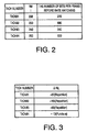
- TrCH#2,22 j is "1180" as indicated by the equation (6):
- TrCH#3, Z3,j is "1813" as indicated by the equation (8).
- ⁇ N3,j is "93" as indicated by the equation (9) :
- TrCH#4,Z4,j is "2400" as indicated by the equation (10):
- TrCH#1 has +67 (Repetition)
- TrCh#2 has +153 (Repetition)
- TrCH#3 has +93 (Repetition)
- TrCH#4 has -13 (Puncturing).
- the calculations of rate matching parameters are performed in a channel codec section in each of transmitting and receiving factions in a mobile station apparatus and a base station apparatus.
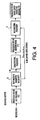
- FIG.4 is a block diagram illustrating a configuration of a channel codec section in a receiving function in a mobile station apparatus.
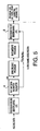
- FIG.5 is a block diagram illustrating a configuration of a channel codec section in a receiving function in a base station apparatus.
- FIG. 6 is a block diagram illustrating a configuration of a channel codec section in a transmitting function in the mobile station apparatus.
- FIG.7 7 is a block diagram illustrating a configuration of a channel codec section in a transmitting function in the base station apparatus.
- each of reference numerals 1, 2, 3 and 4 denotes a rate matching parameter calculator for calculating rate matching parameter.
- Rate matching parameter calculator 1 in the transmitting function outputs rate matching parameters Xi, eini, eplus, and eminus, and based on these rate matching parameters, rate matching processor 5 performs the rate matching processing.
- rate matching parameter calculator 2 in the transmitting function outputs rate matching parameters Xi, eini, eplus, and eminus. Then, based on these rate matching parameters, rate matching processor 6 performs the rate matching processing.
- rate matching parameter calculator 3 in the receiving function outputs rate matching parameters Xi, eini, eplus, and eminus. Then, based on these rate matching parameters, rate matching processor 7 performs the rate matching processing.
- rate matching parameter calculator 4 in the receiving function outputs rate matching parameters Xi, eini, eplus, and eminus. Then, based on these rate matching parameters, rate matching processor 8 performs the rate matching processing.
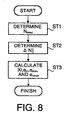
- FIG.8 is a flowchart showing the operation of rate matching parameter calculator 1
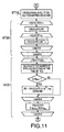
- FIGs.9 to 11 are flowcharts showing the operation of the rate matching parameter calculator 2
- FIG.12 is a flowchart showing the operation of rate matching parameter calculator 4.
- the operation of rate matching parameter calculator 3 is the same as the operation of rate matching parameter calculator 2, and is omitted in showing the flowchart thereof.
- Rate matching parameter calculator 1 determines Ndata,j using a type of data and the number of channels (step 1), and then determines the number of increase or decrease bits on each channel (step 2). After determining the number of increase or decrease bits on each channel, the calculator 1 calculates rate matching parameters Xi, eini, eplus and eminus (step 3).
- Rate matching parameter calculator 2 first receives as its input the number of channels on CCTrCH (step 10). Then, the calculator 2 judges the type of rate matching (step 11). In this case, there are two types of rate matching, namely, Fixed Position and Flexible Position. In the case of Fixed Position, the processing flow proceeds to step 12. At step 12, Ni,. is calculated.
- step 13 it is judged whether a mode is a normal mode or a compressed mode by SF/2 (Spreading factor reduction) (step 13).
- the processing of step 14 is executed. That is, the number of bits is calculated by which the repetition or puncturing is performed within the number of bits per frame on each TrCH, and then the number of bits is calculated by which the repetition or puncturing is performed within the number of bits per TTI on each TrCH. After calculating each of the numbers of bits, the rate matching parameters Xi, eini, eplus and eminus are calculated.
- step 15 is executed after calculating Ni,. at the step 12. That is, the number of bits is calculated by which the repetition or puncturing is performed within the number of bits per frame on each TrCH, and then the number of bits is calculated by which the repetition or puncturing is performed within the number of bits per TTI on each TrCH.
- the calculations are performed based on the maximum TTI among all TrCH to be calculated. As an example, it is assumed that on TrCH with TrCH#1 and TrCH#2 to be calculated, TTI of TrCH#1 is 20 ms, and that TTI of TrCH#2 is 40 ms. At this point, the maximum TTI is 40 ms.
- TTI of TrCH#1 is 20 ms, it is considered that two TTI of TrcE#1 are contained in 40ms. Therefore, the number of bits is calculated twice by which the repetition or puncturing is performed. Meanwhile, since TTI of TrCH#2 is 40 ms, the above calculation is performed once.
- step 16 calculates Pbit that is bit for making a Gap (portion where data transmission is not performed) for the compressed mode.
- Pbit bits per frame are allocated to each TrCH, using on each TrCH, RMi and the number of bits per frame before the base station transmission rate matching (or receiver reception rate matching).
- step 17 the total number of bits for the Pbit is calculated in each TTI on each TrCH.
- step 18 the total number of bits for the Pbit is subtracted from the above-obtained number of increase or decrease bits, whereby the final number of increase or decrease bits in each TTI on each TrCH is obtained.
- the rate matching parameters Xi, eini, eplus and eminus are calculated.
- step 19 the processing flow proceeds to step 19, where Ni, j is calculated in all TF on all TrCH mapped on CCTrCH.
- the temporary number of bits is calculated by which the repetition or puncturing is performed within the number of bits per TTI on each TrCH (step 20).
- D is next calculated in combination of all TF, and examined whether D exceeds Ndata,j (step 21).
- D is indicative of the number of bits on CCTrCH at the time of TFCj.
- D exceeds Ndata,j the number of bits is recalculated by which the repetition or puncturing is performed within the number of bits per TTI on each TrCH.
- D does not exceed Ndata,j the recalculation is not performed.
- each of the rate matching parameters Xi, eini, eplus and eminus is calculated.
- Rate matching parameter calculator 3 performs the same operation as rate matching parameter calculator 2.
- Rate matching parameter calculator 4 determines ⁇ Ni,j corresponding to the type of data and the number of channels (step 30), and then calculates each of rate matching parameters Xi, eini, eplus and eminus (step 31).
- the previously described equation (1) is used to calculate the number of bits on each channel.
- calculating the equation there is a case that a correct result is not obtained due to the accuracy limitation in division. In such a case, there occurs a difference of the calculation result between the transmitting side and receiving side. When such a difference occurs, as described above, the receiving side is incapable of decoding, and as a result, the communication is made impossible.
- the equation (1) is introduced for use in obtaining the number of increase or decrease bits on each channel.
- FIG.13 is a flowchart showing calculation processes of the equation (1) in a rate matching apparatus according to the first example.
- the rate matching apparatus of the first embodiment is comprised of, for example, rate matching parameter calculator 1 and rate matching processor 5 in FIG.6 described previously.
- rate matching apparatus 100 in FIG.6 is used as the rate matching apparatus of the first example.
- Rate matching apparatus 100 first performs the calculation of b/a (step 50) in the calculation of the equation (1), and then adds 1/c 2 to the calculation result (step 51). After adding 1/c 2 , the result is further multiplied by c. As previously described, by adding 1/c 2 to the calculation result of b/a, and multiplying the added result larger than the result of b/a by c, the result becomes larger than the result of the equation (1). That is, since the Floor calculation for rounding down to the nearest one is performed at the final step of the equation (1), if an increased value is smaller than 1, the increased value is abandoned by the rounding down.
- FIG.14 is a block diagram illustrating a section for performing the calculation of the equation (1) in the rate matching apparatus according to the second example.
- the section for performing the calculation of the equation (1) is comprised of abc combination judging section 20, storage table 21, and correction value addition calculating section 22.
- the second example is effective particularly in a case that a correct result is not obtained even using the method in the above-mentioned first example.
- Storage table 21 stores in advance combinations of a, b and c providing incorrect solutions and correct calculation results corresponding to the combinations.
- the combination judging section 20 judges that an input combination of a, b and c is the combination providing the incorrect result, the section 20 reads out the calculation result corresponding to the combination from storage table 21 to output.
- each value of a, b and c is input to correction value addition calculating section 22 that performs the same processing as in the first example, and the correct calculation result is output from the section 22. Accordingly, as well as in the second example, is it possible for both the transmitting side and receiving side to calculate the correct number of bits, and to perform excellent communications.
- a rate matching apparatus first performs the multiplication (b ⁇ c) of the numerator in the calculation in the equation (1), as indicated in the equation (13), and then divides the multiplication result by a.
- X ⁇ b ⁇ c a ⁇
- the embodiment explains a case that the value of b ⁇ c is divided into upper 28 bits and lower 15 bits to calculate, and thereby enables the calculation in the 32-bit calculator.
- the value of bXc is divided into upper 28 bits and lower 15 bits, and a is subtracted from the upper 28 bits. Then, when the subtraction is enabled, "1" is set, while when the subtraction is disabled, "0" is set. Then after finishing the subtraction once, the upper 28. bits are shifted to the left by 1 bit, ⁇ is added to the lowest bit of the lower bits.
- the calculation being performed while shifting the value of upper 28 bits of b/c by 1 bit is repeatedly performed 17 times.
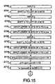
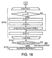
- FIGs.15 to 17 indicate the calculation method of the embodiment.
- FIG.18 is a conceptual view of a memory. The calculation method in the fourth embodiment will be explained specifically below with reference to these drawings.
- a is input, and is shifted to the left by 2 bits (steps 60 and 61).
- b is input, and is shifted to the left by 2 bits (steps 62 and 63).
- the upper 16 bits of b are input to b_up (step 64), and the lower 16 bits of b are input to b_low (step 65).
- c is input, and is shifted to the left by 14 bits (steps 66 and 67).
- the upper 16 bits of c are input to c_up (step 68), and the lower 16 bits of c are input to c_low (step 69).
- b is multiplied by c.
- the multiplication of b by c is calculated using ⁇ and ⁇ obtained in the following.
- ⁇ is first obtained (step 70).
- ⁇ is obtained by adding the product of the upper 16 bits of b input to b_up and the lower 16 bits of c input to c_low and the product of the lower 16 bits of b input to b_low and the upper 16 bits of c input to c_low, and further adding the above-calculated sum to data obtained by shifting the product of the lower 16 bits of b input to b_low and the lower 16 bits of c input to c_low to the right by 16 bits.
- ⁇ is obtained (step 71).
- the upper 16 bits of ⁇ is added to the product of the upper 16 bits of b input of b_up and the upper 16 bits of c input of c_up (the highest bit is a sign bit, and therefore adding the data obtained by shifting to the right by 15 bits equals adding the upper 16 bits).
- the lowest bit of ⁇ is a sign bit, the upper 16 bits contain the upper second to 17th bits correctly.
- the lower 15 bits of are input to bc_lowest.
- the lower 15 bits ⁇ are not input to bc_lowest with no operation, and data obtained by shifting the lower bits to the left by 1 bit is input.
- This operation is performed to move a position of the decimal point of b ⁇ c between the lowest bit and lower second bit.
- the position of the decimal point is associated with that "a is shifted to the left by 2 bits" at the step 61. This is such an operation that moves a position of the decimal point between the lower second and third bits, whereby a difference between the positions of decimal point of a and of that of b ⁇ c is of 17 bits.
- step 73 the calculation is performed while shifting a value indicative of b ⁇ c by 1 bit in a division loop (step 73).
- the difference between the decimal point positions of a and of b ⁇ c is of 17 bits
- performing the processing of the step 17 repeatedly 17 times equals performing the division whose solution is an integer.
- bits remaining in ⁇ are indicative of a remainder of the division.
- the value of b ⁇ c is divided into upper 28 bits and lower 15 bits to calculate, whereby it is possible to perform the calculation using the 32-bit calculator. Accordingly, even in the third example, it is possible for both the transmitting side and receiving side to calculate the correct number of bits, and thereby excellent communications can be performed.
- the calculation amount becomes less than a case that the calculation is performed without dividing the value of bXc into upper bits and lower bits. It is thereby possible to shorten the time taken to complete the rate matching.
- the above-mentioned flowcharts are programmed and stored as data in a storage section such as a memory, and a control section not shown calculates the equation (1) according to the program stored in the storage section.
- the rate matching apparatus is naturally installed in both a mobile station apparatus and a base station apparatus.
- the rate matching apparatus is installed in each of the channel codec section in the receiving function illustrated in FIG.5 and of the channel codec section in the transmitting function illustrated in FIG.7.
- the rate matching apparatus is installed in each of the channel codec section in the receiving function illustrated in FIG.4 and of the channel codec section in the transmitting function illustrated in FIG.6.
- calculation method of the embodiment is applicable to an apparatus that performs division and multiplication, as well as the rate matching apparatus, and has the high usability.
- 1/c 2 is added to the result of b/a in a calculation process of the following equation (1) for use in obtaining the number of increase or decrease bits on each channel for each frame:
- the result of b/a is multiplied by c in the equation (1), however, since there is a case that a calculation result is obtained which is smaller than a true division result due to the calculation accuracy in b/a, it sometimes happens that a value smaller than the true value is obtained as the result of the equation (1).
- the correction value is added to the calculation result of b/a. However, if the correction value is excessively large, a value is calculated which is larger than the true value of the equation (1). Then, 1/c 2 is added in order to prevent the added whole value of the equation (1) from exceeding 1 when c is multiplied. Adding 1/c 2 to the result of b/a is capable of obtaining a correct calculation result.
- a rate matching calculation method has the steps of performing correction where 1/c 2 is added to the result of b/a in a calculation process of the following equation (1) for use in obtaining the number of increase or decrease bits on each channel for each frame:
- the value of b ⁇ c is divided into upper 28 bits and lower 15 bits to calculate, whereby it is possible to perform the calculation using the 32-bit calculator.
- the calculation amount becomes less than a case that the calculation is performed without dividing the value of b ⁇ c into upper bits and lower bits. It is thereby possible to shorten the time taken to complete the rate matching.
- a rate matching apparatus has a configuration provided with a storage section that stores program data of an equation where 1/c 2 is added to the result of b/a of the following equation (1) for use in obtaining the number of increase or decrease bits on each channel for each frame:
- a rate matching apparatus has a configuration provided with a first storage section that stores program data of an equation where 1/c 2 is added to the result of b/a of the following equation (1) for use in obtaining the number of increase or decrease bits on each channel for each frame:
- a rate matching apparatus has a configuration provided with a storage section that stores program data of an equation where 1/c 2 is added to the result of b/a of the following equation (1) for use in obtaining the number of increase or decrease bits on each channel for each frame:
- a mobile station apparatus of the present invention has a configuration provided with any one of the above-mentioned rate matching apparatuses and a transmission/reception apparatus which inputs a frame extracted from a received signal to the rate matching apparatus at the time of receiving signals, while further inputting a frame to be transmitted to the rate matching apparatus at the time of transmitting signals.
Landscapes
- Engineering & Computer Science (AREA)
- Computer Networks & Wireless Communication (AREA)
- Signal Processing (AREA)
- Quality & Reliability (AREA)
- Mobile Radio Communication Systems (AREA)
- Investigating, Analyzing Materials By Fluorescence Or Luminescence (AREA)
- Other Investigation Or Analysis Of Materials By Electrical Means (AREA)
- Analysing Materials By The Use Of Radiation (AREA)
- Facsimile Transmission Control (AREA)
- Electrotherapy Devices (AREA)
Claims (4)
- CDMA-Ratenanpassungsverfahren, das die folgenden Schritte umfasst:(a) Ermitteln der Zahl ΔNij von Zunahme- oder Abnahme-Bits auf jedem Kanal für jeden Rahmen unter Verwendung von Daten Ndataj pro Rahmen auf dem CCTrCH, der Anzahl Nij von Bits vor Ratenanpassung in jedem TrCH, die simultan auf einem Rahmen zu senden sind, und des Gewichtes RMI für jeden Kanal entsprechend der folgenden Gleichung:dadurch gekennzeichnet, dass

wobei Zij eine Zwischenberechnungs-Variable ist, i den Transportkanal darstellt, j die Transportformat-Kombination darstellt und I die Anzahl von Kanälen darstellt, wobei der Wert von Zij mit der folgenden Gleichung ermittelt wird:
wobeia das Additionsergebnis von 1 bis 1 des Produktes von RMi und Nij darstellt;b das Additionsergebnis von 1 bis i des Produktes von RMi und Nij darstellt;c Ndataj darstellt, und(b) Ratenanpassung jedes Kanals auf Basis der Zahl ΔNij von Zunahme- oder Abnahme-Bits;
in Schritt (a) die Divisionsoperation zum Ermitteln von Zij die folgenden Schritte einschließt:(1) wenn das Ergebnis von b*c 32 Bit übersteigt, Unterteilen des Wertes von b*c in obere 28 Bits und untere 15 Bits, Subtrahieren von a von den oberen 28 Bits, Einsetzen von "1" in Zij, wenn die Subtraktion negativ ist, und Einsetzen von "0" in Zij, wenn die Subtraktion nicht negativ ist;(2) nach einmaligen Abschließen der Subtraktion Verschieben der oberen 28 Bits um 1 Bit nach links, Addieren von α zu dem untersten Bit der unteren Bits, wobei α ermittelt wird, indem die oberen 16 Bits von β zu dem Produkt der oberen 16 Bits von b und den oberen 16 Bits von c addiert werden, und β ermittelt wird, indem das Produkt der oberen 16 Bits von b und der unteren 16 Bits von c und das Produkt der unteren 16 Bits von b und der oberen 16 Bits von c addiert werden und weiterhin Daten addiert werden, die ermittelt werden, indem das Produkt der unteren 16 Bits von b und der unteren 16 Bits von c um 16 Bits nach rechts verschoben werden;(3) 17-maliges wiederholtes Durchführen der oben stehenden Subtraktion in Schritt (1) und der Bitverschiebungsbearbeitung in Schritt (2) 17 mal. - CDMA-Ratenanpassungsvorrichtung, die umfasst:(a) einen Berechnungsabschnitt (3), der so eingerichtet ist, dass er die Zahl ΔNij von Zunahme- oder Abnahmebits auf jedem Kanal für jeden Rahmen unter Verwendung von Daten Ndataj pro Rahmen auf dem CCTrCH der Zahl Nij von Bits vor Ratenanpassung in jedem TrCH, die simultan auf einem Rahmen zu senden sind, und des Gewichtes RMI für jeden Kanal entsprechend der folgenden Gleichung ermittelt:

wobei Zij eine Zwischenberechnungs-Variable ist, i den Transportkanal darstellt, j die Transportformat-Kombination darstellt und I die Anzahl von Kanälen darstellt; wobei der Wert von Zij mit der folgenden Gleichung ermittelt wird:
wobeia das Additionsergebnis von 1 bis I des Produktes von RMi und Nij darstellt;b das Additionsergebnis von 1 bis i des Produktes von RMi und Nij darstellt;c Ndataj darstellt; und(b) einen Ratenanpassungsabschnitt (7), der so eingerichtet ist, dass er Ratenanpassung jedes Kanals auf Basis der Zahl von Zunahme- oder Abnahme-Bits ΔNij durchführt;dadurch gekennzeichnet, dass
wenn das Ergebnis von b*c 32 Bits übersteigt und um die Division zum Ermitteln von Zij durchzuführen, der Berechnungsabschnitt des Weiteren so eingerichtet ist, dass er:(1) den Wert von b*c in obere 28 Bits und untere 15 Bits unterteilt, a von den oberen 28 Bits subtrahiert, wobei, wenn die Subtraktion negativ ist, "1" in Zij eingesetzt wird, während, wenn die Subtraktion nicht negativ ist, "0" in Zij eingesetzt wird;(2) nach einmaligem Abschließen der Subtraktion die oberen 28 Bits um 1 Bit nach links verschiebt und zu α das unterste Bit der unteren Bits addiert, wobei α ermittelt wird, indem die oberen 16 Bits von β zu dem Produkt der oberen 16 Bits von b und den oberen 16 Bits von c addiert werden, und β ermittelt wird, indem das Produkt der oberen 16 Bits von b und der unteren 16 Bits von c und das Produkt der unteren 16 Bits von b und der oberen 16 Bits von c addiert werden und weiterhin Daten addiert werden, die ermittelt werden, indem das Produkt der unteren 16 Bits von b und der unteren 16 Bits von c um 16 Bits nach rechts verschoben werden;(3) die Schritte (1) und (2) 17 Mal wiederholt. - Basisstationsvorrichtung, die eine Vorrichtung zum Erzeugen von CDMA-Sendedaten nach Anspruch 2 enthält.
- Mobilstationsvorrichtung, die eine Vorrichtung zum Erzeugen von CDMA-Sendedaten nach Anspruch 2 enthält.
Applications Claiming Priority (2)
| Application Number | Priority Date | Filing Date | Title |
|---|---|---|---|
| JP2000099510 | 2000-03-31 | ||
| JP2000099510 | 2000-03-31 |
Publications (3)
| Publication Number | Publication Date |
|---|---|
| EP1139598A2 EP1139598A2 (de) | 2001-10-04 |
| EP1139598A3 EP1139598A3 (de) | 2004-01-02 |
| EP1139598B1 true EP1139598B1 (de) | 2007-05-09 |
Family
ID=18613851
Family Applications (1)
| Application Number | Title | Priority Date | Filing Date |
|---|---|---|---|
| EP01108191A Expired - Lifetime EP1139598B1 (de) | 2000-03-31 | 2001-03-30 | Verfahren und Vorrichtung zur Rechnung der Ratenanpassung |
Country Status (8)
| Country | Link |
|---|---|
| US (2) | US6907009B2 (de) |
| EP (1) | EP1139598B1 (de) |
| KR (1) | KR100419690B1 (de) |
| CN (1) | CN1224232C (de) |
| AT (1) | ATE362246T1 (de) |
| AU (1) | AU4470801A (de) |
| DE (1) | DE60128286T2 (de) |
| WO (1) | WO2001074032A1 (de) |
Families Citing this family (17)
| Publication number | Priority date | Publication date | Assignee | Title |
|---|---|---|---|---|
| US6473442B1 (en) * | 1999-04-12 | 2002-10-29 | Telefonaktiebolaget Lm Ericsson (Publ) | Communications system and method for matching and balancing the bit rates of transport channels to the bit rate of a physical channel |
| EP1211858B1 (de) * | 2000-11-30 | 2006-12-27 | Matsushita Electric Industrial Co. Ltd. | Verfahren zur Datenraten-Parameterberechnung, Basisstation für drahtlose Kommunikation, und drahtloses Kommunikationssystem |
| US7230978B2 (en) | 2000-12-29 | 2007-06-12 | Infineon Technologies Ag | Channel CODEC processor configurable for multiple wireless communications standards |
| KR100406528B1 (ko) * | 2001-12-04 | 2003-11-20 | 한국전자통신연구원 | 무선통신 단말기 시스템에서의 레이트 매칭 파라미터의계산횟수 축소방법 |
| US7433337B2 (en) * | 2002-04-05 | 2008-10-07 | Interdigital Technology Corporation | Node B and RNC actions during a serving HSDPA cell change |
| US6717927B2 (en) * | 2002-04-05 | 2004-04-06 | Interdigital Technology Corporation | System for efficient recovery of node B buffered data following serving high speed downlink shared channel cell change |
| JP4005400B2 (ja) * | 2002-04-10 | 2007-11-07 | 富士通株式会社 | 送信フォーマット組み合わせ情報選択方法及び移動端末装置 |
| TWI237961B (en) | 2002-04-19 | 2005-08-11 | Interdigital Tech Corp | Receiving station for CDMA wireless system and method |
| US7111226B1 (en) * | 2002-05-31 | 2006-09-19 | Broadcom Corporation | Communication decoder employing single trellis to support multiple code rates and/or multiple modulations |
| US7706405B2 (en) * | 2002-09-12 | 2010-04-27 | Interdigital Technology Corporation | System for efficient recovery of Node-B buffered data following MAC layer reset |
| CN100461658C (zh) * | 2002-10-24 | 2009-02-11 | 中兴通讯股份有限公司 | 宽带码分多址接入系统速率匹配参数优化方法 |
| US7269783B2 (en) * | 2003-04-30 | 2007-09-11 | Lucent Technologies Inc. | Method and apparatus for dedicated hardware and software split implementation of rate matching and de-matching |
| CA2590259C (en) * | 2004-12-07 | 2016-02-16 | Nu-Iron Technology, Llc | Method and system for producing metallic iron nuggets |
| US8315633B2 (en) * | 2005-08-26 | 2012-11-20 | Qualcomm Incorporated | Uplink soft handoff support in UMTS TDD systems for efficient uplink power and rate control |
| KR100888503B1 (ko) * | 2006-12-01 | 2009-03-12 | 한국전자통신연구원 | 통신 시스템의 디레이트 매칭 방법 및 장치 |
| KR101533240B1 (ko) * | 2008-08-25 | 2015-07-03 | 주식회사 팬택 | 이동통신 시스템에서 레이트 매칭을 제어하기 위한 레이트 매칭 장치 및 그 방법 |
| CN101753194A (zh) * | 2008-11-28 | 2010-06-23 | Tcl集团股份有限公司 | 一种td-scdma中的解重复和解删余方法 |
Family Cites Families (11)
| Publication number | Priority date | Publication date | Assignee | Title |
|---|---|---|---|---|
| US5687095A (en) | 1994-11-01 | 1997-11-11 | Lucent Technologies Inc. | Video transmission rate matching for multimedia communication systems |
| JP2000049663A (ja) * | 1998-04-17 | 2000-02-18 | Matsushita Electric Ind Co Ltd | 無線通信装置及び伝送レ―ト制御方法 |
| KR100334819B1 (ko) | 1998-06-05 | 2002-05-02 | 윤종용 | 레이트 매칭을 위한 채널 부호화 장치 및 방법 |
| US6463097B1 (en) * | 1998-10-16 | 2002-10-08 | Koninklijke Philips Electronics N.V. | Rate detection in direct sequence code division multiple access systems |
| KR100315708B1 (ko) * | 1998-12-31 | 2002-02-28 | 윤종용 | 이동통신시스템에서터보인코더의펑처링장치및방법 |
| US6567466B1 (en) * | 1999-02-16 | 2003-05-20 | Agere Systems Inc. | Method and apparatus for determining the data rate of a received signal in a variable data rate orthogonal spread spectrum communication system |
| US6473442B1 (en) * | 1999-04-12 | 2002-10-29 | Telefonaktiebolaget Lm Ericsson (Publ) | Communications system and method for matching and balancing the bit rates of transport channels to the bit rate of a physical channel |
| FR2792788B1 (fr) * | 1999-04-21 | 2001-07-13 | Mitsubishi Electric France | PROCEDE D'EQUILIBRAGE DU RAPPORT Eb/I DANS UN SYSTEME cdma A MULTIPLEXAGE DE SERVICE ET SYSTEME DE TELECOMMUNICATION L'UTILISANT |
| JP3453124B2 (ja) * | 1999-04-27 | 2003-10-06 | ヒューズ・エレクトロニクス・コーポレーション | 通信ネットワークにおいて速度整合アルゴリズムを使用するシステムおよび方法 |
| DE10030407B4 (de) * | 1999-07-14 | 2011-09-01 | Lg Electronics Inc. | Verfahren zur optimalen Ratenanpassung in einem Mobilkommunikationssystem |
| FR2797736B1 (fr) * | 1999-08-19 | 2001-10-12 | Mitsubishi Electric France | Procede de configuration d'un systeme de telecommunications |
-
2001
- 2001-03-30 EP EP01108191A patent/EP1139598B1/de not_active Expired - Lifetime
- 2001-03-30 DE DE60128286T patent/DE60128286T2/de not_active Expired - Lifetime
- 2001-03-30 US US09/820,636 patent/US6907009B2/en not_active Expired - Lifetime
- 2001-03-30 AT AT01108191T patent/ATE362246T1/de not_active IP Right Cessation
- 2001-04-02 AU AU44708/01A patent/AU4470801A/en not_active Abandoned
- 2001-04-02 WO PCT/JP2001/002865 patent/WO2001074032A1/ja not_active Ceased
- 2001-04-02 KR KR10-2001-7015349A patent/KR100419690B1/ko not_active Expired - Lifetime
- 2001-04-02 CN CNB018009050A patent/CN1224232C/zh not_active Expired - Fee Related
-
2004
- 2004-05-06 US US10/839,206 patent/US20040202114A1/en not_active Abandoned
Also Published As
| Publication number | Publication date |
|---|---|
| CN1224232C (zh) | 2005-10-19 |
| WO2001074032A1 (en) | 2001-10-04 |
| ATE362246T1 (de) | 2007-06-15 |
| KR20020019451A (ko) | 2002-03-12 |
| CN1366759A (zh) | 2002-08-28 |
| EP1139598A2 (de) | 2001-10-04 |
| KR100419690B1 (ko) | 2004-02-21 |
| US6907009B2 (en) | 2005-06-14 |
| DE60128286D1 (de) | 2007-06-21 |
| US20010046211A1 (en) | 2001-11-29 |
| EP1139598A3 (de) | 2004-01-02 |
| DE60128286T2 (de) | 2007-08-30 |
| AU4470801A (en) | 2001-10-08 |
| US20040202114A1 (en) | 2004-10-14 |
Similar Documents
| Publication | Publication Date | Title |
|---|---|---|
| EP1139598B1 (de) | Verfahren und Vorrichtung zur Rechnung der Ratenanpassung | |
| EP3096484B1 (de) | Mobilstation | |
| US7274681B2 (en) | Method of multiplexing information in mobile communications, method and apparatus for decoding transport format combination indicator, and mobile station apparatus, base station apparatus and mobile communication system | |
| ITMI960881A1 (it) | Commutazione senza errori con predittore adattabile e procedimento per la sua attuazione | |
| JP3377991B2 (ja) | レートマッチ演算方法及びレートマッチ装置 | |
| US9203444B2 (en) | Rate adjustment apparatus and a rate adjustment method | |
| EP3163775B1 (de) | Verfahren und vorrichtung zur berechnung der durchschnittlichen empfangenen leistung | |
| US20110077018A1 (en) | Rate adjustment apparatus and method, and communication apparatus | |
| HK1096509B (en) | Method for balancing the ratio eb/i in a service multiplexing cdma system and telecommunication systems using this method |
Legal Events
| Date | Code | Title | Description |
|---|---|---|---|
| PUAI | Public reference made under article 153(3) epc to a published international application that has entered the european phase |
Free format text: ORIGINAL CODE: 0009012 |
|
| AK | Designated contracting states |
Kind code of ref document: A2 Designated state(s): AT BE CH CY DE DK ES FI FR GB GR IE IT LI LU MC NL PT SE TR |
|
| AX | Request for extension of the european patent |
Free format text: AL;LT;LV;MK;RO;SI |
|
| 17P | Request for examination filed |
Effective date: 20021009 |
|
| PUAL | Search report despatched |
Free format text: ORIGINAL CODE: 0009013 |
|
| AK | Designated contracting states |
Kind code of ref document: A3 Designated state(s): AT BE CH CY DE DK ES FI FR GB GR IE IT LI LU MC NL PT SE TR |
|
| AX | Request for extension of the european patent |
Extension state: AL LT LV MK RO SI |
|
| 17Q | First examination report despatched |
Effective date: 20040511 |
|
| AKX | Designation fees paid |
Designated state(s): AT BE CH CY DE DK ES FI FR GB GR IE IT LI LU MC NL PT SE TR |
|
| GRAP | Despatch of communication of intention to grant a patent |
Free format text: ORIGINAL CODE: EPIDOSNIGR1 |
|
| GRAS | Grant fee paid |
Free format text: ORIGINAL CODE: EPIDOSNIGR3 |
|
| GRAA | (expected) grant |
Free format text: ORIGINAL CODE: 0009210 |
|
| AK | Designated contracting states |
Kind code of ref document: B1 Designated state(s): AT BE CH CY DE DK ES FI FR GB GR IE IT LI LU MC NL PT SE TR |
|
| PG25 | Lapsed in a contracting state [announced via postgrant information from national office to epo] |
Ref country code: CH Free format text: LAPSE BECAUSE OF FAILURE TO SUBMIT A TRANSLATION OF THE DESCRIPTION OR TO PAY THE FEE WITHIN THE PRESCRIBED TIME-LIMIT Effective date: 20070509 Ref country code: LI Free format text: LAPSE BECAUSE OF FAILURE TO SUBMIT A TRANSLATION OF THE DESCRIPTION OR TO PAY THE FEE WITHIN THE PRESCRIBED TIME-LIMIT Effective date: 20070509 Ref country code: FI Free format text: LAPSE BECAUSE OF FAILURE TO SUBMIT A TRANSLATION OF THE DESCRIPTION OR TO PAY THE FEE WITHIN THE PRESCRIBED TIME-LIMIT Effective date: 20070509 |
|
| REG | Reference to a national code |
Ref country code: GB Ref legal event code: FG4D |
|
| REG | Reference to a national code |
Ref country code: CH Ref legal event code: EP |
|
| REG | Reference to a national code |
Ref country code: IE Ref legal event code: FG4D |
|
| REF | Corresponds to: |
Ref document number: 60128286 Country of ref document: DE Date of ref document: 20070621 Kind code of ref document: P |
|
| PG25 | Lapsed in a contracting state [announced via postgrant information from national office to epo] |
Ref country code: SE Free format text: LAPSE BECAUSE OF FAILURE TO SUBMIT A TRANSLATION OF THE DESCRIPTION OR TO PAY THE FEE WITHIN THE PRESCRIBED TIME-LIMIT Effective date: 20070809 |
|
| PG25 | Lapsed in a contracting state [announced via postgrant information from national office to epo] |
Ref country code: ES Free format text: LAPSE BECAUSE OF FAILURE TO SUBMIT A TRANSLATION OF THE DESCRIPTION OR TO PAY THE FEE WITHIN THE PRESCRIBED TIME-LIMIT Effective date: 20070820 |
|
| ET | Fr: translation filed | ||
| NLV1 | Nl: lapsed or annulled due to failure to fulfill the requirements of art. 29p and 29m of the patents act | ||
| REG | Reference to a national code |
Ref country code: CH Ref legal event code: PL |
|
| PG25 | Lapsed in a contracting state [announced via postgrant information from national office to epo] |
Ref country code: AT Free format text: LAPSE BECAUSE OF FAILURE TO SUBMIT A TRANSLATION OF THE DESCRIPTION OR TO PAY THE FEE WITHIN THE PRESCRIBED TIME-LIMIT Effective date: 20070509 |
|
| PG25 | Lapsed in a contracting state [announced via postgrant information from national office to epo] |
Ref country code: BE Free format text: LAPSE BECAUSE OF FAILURE TO SUBMIT A TRANSLATION OF THE DESCRIPTION OR TO PAY THE FEE WITHIN THE PRESCRIBED TIME-LIMIT Effective date: 20070509 |
|
| PG25 | Lapsed in a contracting state [announced via postgrant information from national office to epo] |
Ref country code: PT Free format text: LAPSE BECAUSE OF FAILURE TO SUBMIT A TRANSLATION OF THE DESCRIPTION OR TO PAY THE FEE WITHIN THE PRESCRIBED TIME-LIMIT Effective date: 20071009 Ref country code: DK Free format text: LAPSE BECAUSE OF FAILURE TO SUBMIT A TRANSLATION OF THE DESCRIPTION OR TO PAY THE FEE WITHIN THE PRESCRIBED TIME-LIMIT Effective date: 20070509 Ref country code: NL Free format text: LAPSE BECAUSE OF FAILURE TO SUBMIT A TRANSLATION OF THE DESCRIPTION OR TO PAY THE FEE WITHIN THE PRESCRIBED TIME-LIMIT Effective date: 20070509 |
|
| PLBE | No opposition filed within time limit |
Free format text: ORIGINAL CODE: 0009261 |
|
| STAA | Information on the status of an ep patent application or granted ep patent |
Free format text: STATUS: NO OPPOSITION FILED WITHIN TIME LIMIT |
|
| 26N | No opposition filed |
Effective date: 20080212 |
|
| PG25 | Lapsed in a contracting state [announced via postgrant information from national office to epo] |
Ref country code: GR Free format text: LAPSE BECAUSE OF FAILURE TO SUBMIT A TRANSLATION OF THE DESCRIPTION OR TO PAY THE FEE WITHIN THE PRESCRIBED TIME-LIMIT Effective date: 20070810 Ref country code: IT Free format text: LAPSE BECAUSE OF FAILURE TO SUBMIT A TRANSLATION OF THE DESCRIPTION OR TO PAY THE FEE WITHIN THE PRESCRIBED TIME-LIMIT Effective date: 20070509 |
|
| PG25 | Lapsed in a contracting state [announced via postgrant information from national office to epo] |
Ref country code: MC Free format text: LAPSE BECAUSE OF NON-PAYMENT OF DUE FEES Effective date: 20080331 |
|
| PG25 | Lapsed in a contracting state [announced via postgrant information from national office to epo] |
Ref country code: IE Free format text: LAPSE BECAUSE OF NON-PAYMENT OF DUE FEES Effective date: 20080331 |
|
| PG25 | Lapsed in a contracting state [announced via postgrant information from national office to epo] |
Ref country code: CY Free format text: LAPSE BECAUSE OF FAILURE TO SUBMIT A TRANSLATION OF THE DESCRIPTION OR TO PAY THE FEE WITHIN THE PRESCRIBED TIME-LIMIT Effective date: 20070509 |
|
| PG25 | Lapsed in a contracting state [announced via postgrant information from national office to epo] |
Ref country code: LU Free format text: LAPSE BECAUSE OF NON-PAYMENT OF DUE FEES Effective date: 20080330 |
|
| PG25 | Lapsed in a contracting state [announced via postgrant information from national office to epo] |
Ref country code: TR Free format text: LAPSE BECAUSE OF FAILURE TO SUBMIT A TRANSLATION OF THE DESCRIPTION OR TO PAY THE FEE WITHIN THE PRESCRIBED TIME-LIMIT Effective date: 20070509 |
|
| REG | Reference to a national code |
Ref country code: GB Ref legal event code: 732E Free format text: REGISTERED BETWEEN 20140612 AND 20140618 |
|
| REG | Reference to a national code |
Ref country code: DE Ref legal event code: R082 Ref document number: 60128286 Country of ref document: DE Representative=s name: GRUENECKER, KINKELDEY, STOCKMAIR & SCHWANHAEUS, DE |
|
| REG | Reference to a national code |
Ref country code: DE Ref legal event code: R081 Ref document number: 60128286 Country of ref document: DE Owner name: III HOLDINGS 12, LLC, WILMINGTON, US Free format text: FORMER OWNER: PANASONIC CORPORATION, KADOMA-SHI, OSAKA, JP Effective date: 20140711 Ref country code: DE Ref legal event code: R082 Ref document number: 60128286 Country of ref document: DE Representative=s name: GRUENECKER, KINKELDEY, STOCKMAIR & SCHWANHAEUS, DE Effective date: 20140711 Ref country code: DE Ref legal event code: R081 Ref document number: 60128286 Country of ref document: DE Owner name: PANASONIC INTELLECTUAL PROPERTY CORPORATION OF, US Free format text: FORMER OWNER: PANASONIC CORPORATION, KADOMA-SHI, OSAKA, JP Effective date: 20140711 Ref country code: DE Ref legal event code: R082 Ref document number: 60128286 Country of ref document: DE Representative=s name: GRUENECKER PATENT- UND RECHTSANWAELTE PARTG MB, DE Effective date: 20140711 |
|
| REG | Reference to a national code |
Ref country code: FR Ref legal event code: TP Owner name: PANASONIC INTELLECTUAL PROPERTY CORPORATION OF, US Effective date: 20140722 |
|
| REG | Reference to a national code |
Ref country code: FR Ref legal event code: PLFP Year of fee payment: 16 |
|
| REG | Reference to a national code |
Ref country code: FR Ref legal event code: PLFP Year of fee payment: 17 |
|
| PGFP | Annual fee paid to national office [announced via postgrant information from national office to epo] |
Ref country code: FR Payment date: 20170213 Year of fee payment: 17 Ref country code: DE Payment date: 20170321 Year of fee payment: 17 |
|
| PGFP | Annual fee paid to national office [announced via postgrant information from national office to epo] |
Ref country code: GB Payment date: 20170329 Year of fee payment: 17 |
|
| REG | Reference to a national code |
Ref country code: DE Ref legal event code: R082 Ref document number: 60128286 Country of ref document: DE Representative=s name: GRUENECKER PATENT- UND RECHTSANWAELTE PARTG MB, DE Ref country code: DE Ref legal event code: R081 Ref document number: 60128286 Country of ref document: DE Owner name: III HOLDINGS 12, LLC, WILMINGTON, US Free format text: FORMER OWNER: PANASONIC INTELLECTUAL PROPERTY CORPORATION OF AMERICA, TORRANCE, CALIF., US |
|
| REG | Reference to a national code |
Ref country code: GB Ref legal event code: 732E Free format text: REGISTERED BETWEEN 20170727 AND 20170802 |
|
| REG | Reference to a national code |
Ref country code: FR Ref legal event code: TP Owner name: III HOLDINGS 12, LLC, US Effective date: 20171207 |
|
| REG | Reference to a national code |
Ref country code: DE Ref legal event code: R119 Ref document number: 60128286 Country of ref document: DE |
|
| GBPC | Gb: european patent ceased through non-payment of renewal fee |
Effective date: 20180330 |
|
| PG25 | Lapsed in a contracting state [announced via postgrant information from national office to epo] |
Ref country code: DE Free format text: LAPSE BECAUSE OF NON-PAYMENT OF DUE FEES Effective date: 20181002 |
|
| PG25 | Lapsed in a contracting state [announced via postgrant information from national office to epo] |
Ref country code: GB Free format text: LAPSE BECAUSE OF NON-PAYMENT OF DUE FEES Effective date: 20180330 |
|
| PG25 | Lapsed in a contracting state [announced via postgrant information from national office to epo] |
Ref country code: FR Free format text: LAPSE BECAUSE OF NON-PAYMENT OF DUE FEES Effective date: 20180331 |