EP1139697A2 - Vitrage avec connexion électrique - Google Patents
Vitrage avec connexion électrique Download PDFInfo
- Publication number
- EP1139697A2 EP1139697A2 EP01200704A EP01200704A EP1139697A2 EP 1139697 A2 EP1139697 A2 EP 1139697A2 EP 01200704 A EP01200704 A EP 01200704A EP 01200704 A EP01200704 A EP 01200704A EP 1139697 A2 EP1139697 A2 EP 1139697A2
- Authority
- EP
- European Patent Office
- Prior art keywords
- glazing
- connection
- ribbon
- plates
- shell
- Prior art date
- Legal status (The legal status is an assumption and is not a legal conclusion. Google has not performed a legal analysis and makes no representation as to the accuracy of the status listed.)
- Granted
Links
- 239000000463 material Substances 0.000 claims description 21
- 238000002347 injection Methods 0.000 claims description 9
- 239000007924 injection Substances 0.000 claims description 9
- 239000011810 insulating material Substances 0.000 claims description 9
- 238000000465 moulding Methods 0.000 claims description 9
- 239000011521 glass Substances 0.000 claims description 4
- 238000007789 sealing Methods 0.000 claims description 4
- 238000009413 insulation Methods 0.000 claims description 2
- 230000006835 compression Effects 0.000 claims 1
- 238000007906 compression Methods 0.000 claims 1
- 230000000717 retained effect Effects 0.000 claims 1
- 239000002184 metal Substances 0.000 abstract description 3
- 229910052751 metal Inorganic materials 0.000 abstract description 3
- 239000011257 shell material Substances 0.000 description 23
- 230000015572 biosynthetic process Effects 0.000 description 4
- 238000010438 heat treatment Methods 0.000 description 4
- 238000000034 method Methods 0.000 description 4
- 238000003466 welding Methods 0.000 description 4
- 239000004814 polyurethane Substances 0.000 description 3
- 229920002635 polyurethane Polymers 0.000 description 3
- RYGMFSIKBFXOCR-UHFFFAOYSA-N Copper Chemical compound [Cu] RYGMFSIKBFXOCR-UHFFFAOYSA-N 0.000 description 2
- XEEYBQQBJWHFJM-UHFFFAOYSA-N Iron Chemical compound [Fe] XEEYBQQBJWHFJM-UHFFFAOYSA-N 0.000 description 2
- 229910052802 copper Inorganic materials 0.000 description 2
- 239000010949 copper Substances 0.000 description 2
- 239000011229 interlayer Substances 0.000 description 2
- 239000010410 layer Substances 0.000 description 2
- 230000003647 oxidation Effects 0.000 description 2
- 238000007254 oxidation reaction Methods 0.000 description 2
- 229920002037 poly(vinyl butyral) polymer Polymers 0.000 description 2
- 229920000915 polyvinyl chloride Polymers 0.000 description 2
- 239000004800 polyvinyl chloride Substances 0.000 description 2
- 230000001681 protective effect Effects 0.000 description 2
- 230000035484 reaction time Effects 0.000 description 2
- 238000003860 storage Methods 0.000 description 2
- 229920001169 thermoplastic Polymers 0.000 description 2
- 239000004416 thermosoftening plastic Substances 0.000 description 2
- FGRBYDKOBBBPOI-UHFFFAOYSA-N 10,10-dioxo-2-[4-(N-phenylanilino)phenyl]thioxanthen-9-one Chemical compound O=C1c2ccccc2S(=O)(=O)c2ccc(cc12)-c1ccc(cc1)N(c1ccccc1)c1ccccc1 FGRBYDKOBBBPOI-UHFFFAOYSA-N 0.000 description 1
- 229910001369 Brass Inorganic materials 0.000 description 1
- 239000004698 Polyethylene Substances 0.000 description 1
- 239000004793 Polystyrene Substances 0.000 description 1
- 239000010951 brass Substances 0.000 description 1
- 238000006243 chemical reaction Methods 0.000 description 1
- 230000001143 conditioned effect Effects 0.000 description 1
- 238000004132 cross linking Methods 0.000 description 1
- 125000004122 cyclic group Chemical group 0.000 description 1
- 230000006866 deterioration Effects 0.000 description 1
- 230000005489 elastic deformation Effects 0.000 description 1
- 238000010292 electrical insulation Methods 0.000 description 1
- 239000012943 hotmelt Substances 0.000 description 1
- 229910052742 iron Inorganic materials 0.000 description 1
- 238000004519 manufacturing process Methods 0.000 description 1
- 239000000203 mixture Substances 0.000 description 1
- 239000012768 molten material Substances 0.000 description 1
- 238000004806 packaging method and process Methods 0.000 description 1
- 230000002093 peripheral effect Effects 0.000 description 1
- 229920000728 polyester Polymers 0.000 description 1
- -1 polyethylene Polymers 0.000 description 1
- 229920000573 polyethylene Polymers 0.000 description 1
- 229920000642 polymer Polymers 0.000 description 1
- 229920002223 polystyrene Polymers 0.000 description 1
- 238000004080 punching Methods 0.000 description 1
- 230000035945 sensitivity Effects 0.000 description 1
- 238000005476 soldering Methods 0.000 description 1
- 238000007711 solidification Methods 0.000 description 1
- 230000008023 solidification Effects 0.000 description 1
- 239000012815 thermoplastic material Substances 0.000 description 1
- XOLBLPGZBRYERU-UHFFFAOYSA-N tin dioxide Chemical compound O=[Sn]=O XOLBLPGZBRYERU-UHFFFAOYSA-N 0.000 description 1
- 229910001887 tin oxide Inorganic materials 0.000 description 1
- 238000011282 treatment Methods 0.000 description 1
- 238000004804 winding Methods 0.000 description 1
Images

Classifications
-
- B—PERFORMING OPERATIONS; TRANSPORTING
- B32—LAYERED PRODUCTS
- B32B—LAYERED PRODUCTS, i.e. PRODUCTS BUILT-UP OF STRATA OF FLAT OR NON-FLAT, e.g. CELLULAR OR HONEYCOMB, FORM
- B32B17/00—Layered products essentially comprising sheet glass, or glass, slag, or like fibres
- B32B17/06—Layered products essentially comprising sheet glass, or glass, slag, or like fibres comprising glass as the main or only constituent of a layer, next to another layer of a specific material
- B32B17/10—Layered products essentially comprising sheet glass, or glass, slag, or like fibres comprising glass as the main or only constituent of a layer, next to another layer of a specific material of synthetic resin
- B32B17/10005—Layered products essentially comprising sheet glass, or glass, slag, or like fibres comprising glass as the main or only constituent of a layer, next to another layer of a specific material of synthetic resin laminated safety glass or glazing
- B32B17/10009—Layered products essentially comprising sheet glass, or glass, slag, or like fibres comprising glass as the main or only constituent of a layer, next to another layer of a specific material of synthetic resin laminated safety glass or glazing characterized by the number, the constitution or treatment of glass sheets
- B32B17/10036—Layered products essentially comprising sheet glass, or glass, slag, or like fibres comprising glass as the main or only constituent of a layer, next to another layer of a specific material of synthetic resin laminated safety glass or glazing characterized by the number, the constitution or treatment of glass sheets comprising two outer glass sheets
-
- B—PERFORMING OPERATIONS; TRANSPORTING
- B32—LAYERED PRODUCTS
- B32B—LAYERED PRODUCTS, i.e. PRODUCTS BUILT-UP OF STRATA OF FLAT OR NON-FLAT, e.g. CELLULAR OR HONEYCOMB, FORM
- B32B17/00—Layered products essentially comprising sheet glass, or glass, slag, or like fibres
- B32B17/06—Layered products essentially comprising sheet glass, or glass, slag, or like fibres comprising glass as the main or only constituent of a layer, next to another layer of a specific material
- B32B17/10—Layered products essentially comprising sheet glass, or glass, slag, or like fibres comprising glass as the main or only constituent of a layer, next to another layer of a specific material of synthetic resin
- B32B17/10005—Layered products essentially comprising sheet glass, or glass, slag, or like fibres comprising glass as the main or only constituent of a layer, next to another layer of a specific material of synthetic resin laminated safety glass or glazing
- B32B17/10165—Functional features of the laminated safety glass or glazing
- B32B17/10293—Edge features, e.g. inserts or holes
-
- B—PERFORMING OPERATIONS; TRANSPORTING
- B32—LAYERED PRODUCTS
- B32B—LAYERED PRODUCTS, i.e. PRODUCTS BUILT-UP OF STRATA OF FLAT OR NON-FLAT, e.g. CELLULAR OR HONEYCOMB, FORM
- B32B17/00—Layered products essentially comprising sheet glass, or glass, slag, or like fibres
- B32B17/06—Layered products essentially comprising sheet glass, or glass, slag, or like fibres comprising glass as the main or only constituent of a layer, next to another layer of a specific material
- B32B17/10—Layered products essentially comprising sheet glass, or glass, slag, or like fibres comprising glass as the main or only constituent of a layer, next to another layer of a specific material of synthetic resin
- B32B17/10005—Layered products essentially comprising sheet glass, or glass, slag, or like fibres comprising glass as the main or only constituent of a layer, next to another layer of a specific material of synthetic resin laminated safety glass or glazing
- B32B17/10165—Functional features of the laminated safety glass or glazing
- B32B17/10376—Laminated safety glass or glazing containing metal wires
- B32B17/10385—Laminated safety glass or glazing containing metal wires for ohmic resistance heating
-
- B—PERFORMING OPERATIONS; TRANSPORTING
- B32—LAYERED PRODUCTS
- B32B—LAYERED PRODUCTS, i.e. PRODUCTS BUILT-UP OF STRATA OF FLAT OR NON-FLAT, e.g. CELLULAR OR HONEYCOMB, FORM
- B32B17/00—Layered products essentially comprising sheet glass, or glass, slag, or like fibres
- B32B17/06—Layered products essentially comprising sheet glass, or glass, slag, or like fibres comprising glass as the main or only constituent of a layer, next to another layer of a specific material
- B32B17/10—Layered products essentially comprising sheet glass, or glass, slag, or like fibres comprising glass as the main or only constituent of a layer, next to another layer of a specific material of synthetic resin
- B32B17/10005—Layered products essentially comprising sheet glass, or glass, slag, or like fibres comprising glass as the main or only constituent of a layer, next to another layer of a specific material of synthetic resin laminated safety glass or glazing
- B32B17/1055—Layered products essentially comprising sheet glass, or glass, slag, or like fibres comprising glass as the main or only constituent of a layer, next to another layer of a specific material of synthetic resin laminated safety glass or glazing characterized by the resin layer, i.e. interlayer
- B32B17/10761—Layered products essentially comprising sheet glass, or glass, slag, or like fibres comprising glass as the main or only constituent of a layer, next to another layer of a specific material of synthetic resin laminated safety glass or glazing characterized by the resin layer, i.e. interlayer containing vinyl acetal
-
- H—ELECTRICITY
- H05—ELECTRIC TECHNIQUES NOT OTHERWISE PROVIDED FOR
- H05B—ELECTRIC HEATING; ELECTRIC LIGHT SOURCES NOT OTHERWISE PROVIDED FOR; CIRCUIT ARRANGEMENTS FOR ELECTRIC LIGHT SOURCES, IN GENERAL
- H05B3/00—Ohmic-resistance heating
- H05B3/84—Heating arrangements specially adapted for transparent or reflecting areas, e.g. for demisting or de-icing windows, mirrors or vehicle windshields
-
- H—ELECTRICITY
- H05—ELECTRIC TECHNIQUES NOT OTHERWISE PROVIDED FOR
- H05B—ELECTRIC HEATING; ELECTRIC LIGHT SOURCES NOT OTHERWISE PROVIDED FOR; CIRCUIT ARRANGEMENTS FOR ELECTRIC LIGHT SOURCES, IN GENERAL
- H05B2203/00—Aspects relating to Ohmic resistive heating covered by group H05B3/00
- H05B2203/016—Heaters using particular connecting means
Definitions
- the present invention relates to a mode of connection between one or several functional elements arranged in, or on an automobile window, requiring a power supply on the one hand, and the power circuit on the other go.
- conductive strips are arranged on the glazing, on the edges of it.
- These collector strips are most usually made up of a ribbon metallic a few millimeters wide and a few hundredths of a millimeter thick.
- the metallic ribbon is either fixed on a single sheet, or arranged on one of the faces of the glazing in contact with the thermoplastic interlayer, in the case of a laminated glazing.
- a difficulty in the connections between the power supply and the glazing is linked to the relative fragility of these metallic ribbons.
- the junction between the cables power supply and glazing exposes this connection on the one hand to efforts as long as the glazing is not in place, and subsequently to all vibrations specific to the vehicle.
- the connection set up must therefore offer all the resistance required, regardless of the additional means usually used implemented to protect its integrity, the risks of false contacts linked to oxidation, etc.
- a usual mode of connection consists in soldering the end metallic tape on the power cable.
- practice in this case is to wrap this end of the metal tape, which extends beyond the edge of the glazing, on the end of the cable, previously stripped, and weld the assembly.
- the connection is advantageously taken in an envelope of insulating material, of the polymer type, which simultaneously keeps the connection in position by sticking it to the edge of the glazing.
- connection element comprising two distinct parts: a first part which forms a sleeve, of shape and dimensions corresponding to those of the power cable, and a second part consisting of two plates assembled by a foldable side, of the jaw type.
- the two plates of this second part are of such dimensions that they can cover and imprison the end of the collecting tape.
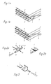
- Figure 1a shows a laminated glazing consisting of two sheets of glass 2 and 2 ', and an interlayer sheet 3, of thermoplastic material such as polyvinyl butyral (PVB).
- the glazing is cut along a collecting tape electrical 1.
- the collecting tape is for example tinned copper. Its width is by example of 6mm and its thickness of 0.1mm.
- the heating elements are not represented. These are for example networks of wires of very small diameter, according to a fashion known per se. It can also be, to constitute a heated glazing, to supply a thin conductive layer, for example based on tin oxide, deposited on one of the glass sheets.
- the conductive tape 1 extends beyond the edge of the glazing to allow connection to the power supply represented by the cable corresponding 4.
- the insulating sheath of the cable is removed at the end to allow connection.
- the ribbon is folded and wound on the end of the cable as shown in Figure 1b.
- the assembly is then welded to ensure the permanence of the connection.
- the connection made is then wrapped, according to a traditional mode, in an insulating material, which simultaneously fixes the connection to the edge of the glazing.
- connection mode produced according to the invention is presented to Figures 2a and 2b.
- connection element 5 To simplify the drawings, only the end of the collecting tape, the end of the cable 4, and a connection element 5 are shown.
- connection element comprises a first part whose shape and dimensions are substantially adapted to those of the end of the cable 4.
- this part of the connector is in the form of cylindrical sleeve.
- a second part 7 of the connector is intended to receive the ribbon 1. It consists of two plates 8 and 9 joined to each other by at minus part of one of their sides. The two plates 8 and 9 can be folded down one on the other to enclose the end of the ribbon 1 in the jaw they constitute.
- connection element is produced in a known manner in a sheet conductive metal.
- a sheet conductive metal is a tinned iron sheet, copper, brass ...
- the thickness of the sheet forming the connector 5 is both thick enough to provide good rigidity once the connection is made, and not too thick to allow the deformations which ensure adequate contacts, without requiring considerable effort.
- the implementation of the connector obviously follows from its constitution. It includes the introduction of the end of the cable 4 into the sleeve 6.
- the fixing is done by crushing the sleeve on the cable. She may be improved by modifying the internal surface of this sleeve. For example, to create streaks, or any other roughness that prevents the cable from moving trapped in the sleeve.
- the fixing can obviously result from a welding of the cable and of the sleeve.
- This welding can also be combined with the crushing of the sleeve.
- crushing is sufficient to guarantee good electrical contact, the characteristics of which do not will not deteriorate over time, especially when the connection is caught in its insulating envelope which protects it from oxidation.
- Welding if practiced also allows to fill the gaps between the cable and the sleeve, and between the wires of the cable themselves obviously improving the contact.
- the latter advantageously have parts projecting in ribbon direction. It can be teeth, streaks or any other relief which closing the jaw will give a limited local deformation of the ribbon.
- the simplest method of modifying the relief of the plates consists of pins resulting from the punching of the plates. Regardless of the presence or not of these "teeth" on the plates, the fixing and the electrical contact can be reinforced by the welding of the assembly constituted by the two plates and the end ribbon.
- Figure 2a shows the different elements before they are brought together.
- the figure 2b shows the connector with the power cable in position in the sleeve 6, and the collecting tape taken from the jaw 7.
- cable 4 and ribbon 1 are attached to connector 5 is not critical. For the convenience of the operation, preferably the cable fixing, then to that of the ribbon.
- the position of the connector is such that the cable is substantially parallel to the edge of the glazing. This provision limits the relative size of this connection. Indeed, the protuberance that constitutes the entire connection, its enclosure, and the power cable, can be difficult to fit into vehicle body openings. A lesser space is also preferable for the storage and transport of glazing. However, other arrangements are possible, such as that shown in the figure 3. In this one the power cable is in line with the ribbon collector.
- the insulating material is therefore also chosen according to its ability to adhere securely to glazing.
- a moldable product such as polyurethane, polyvinyl chloride, various polyesters and the like.
- the adhesion qualities of polyurethane make it a product well suited for this use.
- Figure 4 shows the connection according to the invention in its envelope insulating11, the latter in section to show the arrangement of the various elements.
- the representation shows the connection 5 fully embedded in the envelope material 11.
- the envelope 11 also includes the cable on a short length, thus protecting the connection area with the connector. Of this way the electrical insulation is suitably ensured, as is the mechanical protection of fragile points.
- the envelope 11 allows in particular the fixing the assembly to the edge of the glazing. So that this fixation is suitably secured, the envelope 11 is advantageously extended as shown in 12, by a projection on the faces of the glazing.
- the molding of the insulating jacket on the connection is an operation which immobilizes all the glazing on the molding station until the mass of the material.
- the duration of this operation obviously depends on the type of material used.
- the hot melt insulation products which are certainly those with the shortest cure times are generally not not used for this type of product because of their sensitivity to heat.
- the reaction time of these products is often several minutes during which the glazing remains on the molding station.
- the post of molding is unavailable during this time, which requires the multiplication of stations to obtain a satisfactory production rate. So in the case envelopes made of polyurethane, a material that is widely used with glazing automotive, reaction time before demoulding can be about 5 minutes. It is desirable to be able to overcome this constraint.
- the speed of the crosslinking process having been optimized, an improvement additional requires other provisions.
- the invention proposes to break with the previous practice aimed at the use of complex molding stations, comprising not only the means packaging, but also molds allowing cyclic regulation of the temperature according to the progress of the operation.
- the invention proposes replacing traditional molds with simple shells which are separable from the material injection station. Once completed, the shells follow the glazing on a storage area or progress in the subsequent treatments, without waiting for the composition to harden.
- FIG. 5 shows the type of means that can be used to carry out this formation of the insulating envelope by overcoming the stress induced by the curing time of the material constituting this envelope. So general, the connections once established, a shell 12 is put in place which completely covers the connection. In the form presented, the shell 12 is consisting of two half shells 13 and 14.
- the hinge 15 is formed by a simple thinning of the side wall of the shell along the line of articulation.
- the geometry of the shell is conditioned by the use of the latter.
- the latter is either kept in position on the glazing permanently, or removed after the material of the insulating jacket is sufficiently stiffened.
- the shell should essentially participate in the protection of the connection.
- the rigidity of the shell regardless of the material chosen, can be obtained by ribs internal, which would oppose an easy release.
- the external surface of the shell is free of projecting parts.
- the shell material is advantageously synthetic of the type polystyrene, polyvinyl chloride, polyethylene etc.
- the choice of material is good understood depending on the nature of the molded material.
- the shell material should necessarily resist contact with the molded material under the conditions of its use. If the material is thermoplastic and injected in the molten state, you must choose a shell which does not soften on contact with the molten material.
- the shell should also chemically resist the material components used to form the envelope.
- the shell 12 is arranged, on the side facing the glazing, such so that once closed, as in Figure 6, it covers on a small part the glazing faces.
- the profile is such that the edges 16, 17 of the shell adjust exactly to the thickness of the glazing, guaranteeing the tightness of the mold-glazing assembly.
- the shell shown in FIG. 5 also includes cutouts 18, 19, for the passage of the supply cable 4.
- An injection orifice 23 is shown diagrammatically on face 14.
- Vents 24 are also arranged in the walls of the shell to evacuate the air during material injection.
- a single injection port 23 is shown. It is possible to provide several, although the limited dimensions of the shell do not require it normally not.
- the closing of the shell must be ensured stably during the injection and the solidification period of the injected material.
- the closure can be provided by means external to the shell, or, as in FIGS. 6 and 8, by elements integrated into it.
- the closing element 20 is for example of the type "pawl".
- the shape shown in Figure 8 has on the wall 13, an extension in the form of a hook 21 which is adapted to a tooth 22, formed on the wall 14. In the shape indicated the hook 21 and the tooth 22 are integral parts of the walls 13 and 14.
- the semi-rigid nature of the material lends itself to the formation of these means for the intended click-in.
- the two half shells are part of the same room, they can, without this fundamentally changing their use, constitute two separate parts which are assembled only for the operation of molding.
Landscapes
- Joining Of Glass To Other Materials (AREA)
- Multi-Conductor Connections (AREA)
- Connector Housings Or Holding Contact Members (AREA)
- Installation Of Indoor Wiring (AREA)
- Resistance Heating (AREA)
- Insulating Bodies (AREA)
- Injection Moulding Of Plastics Or The Like (AREA)
Abstract
Description
- les figures 1a et 1b représentent en perspective un mode de réalisation antérieur du type de connexion envisagé selon l'invention ;
- les figures 2a et 2b représentent un mode de mise en oeuvre d'une connexion selon l'invention ;
- la figure 3 montre une autre forme de réalisation de connexion selon l'invention ;
- la figure 4 illustre en coupe partielle un type de connexion selon l'invention dans une enveloppe protectrice ;
- la figure 5 illustre les moyens utilisés selon l'invention pour réaliser une enveloppe protectrice de la connexion ;
- la figure 6 présente en vue de côté l'ensemble du bord du vitrage comportant la connexion et les moyens de formation de l'enveloppe de la figure 5, en position fermée;
- les figures 7a et 7b, montrent schématiquement des modes d'emboítement des moyens utilisés pour réaliser l'enveloppe de la connexion des figures 5 et 6, en coupe selon la ligne A-A;
- la figure 8 est une illustration d'un mode de fermeture de moyens utilisés pour réaliser l'enveloppe de la connexion.
Claims (10)
- Vitrage automobile équipé d'un ou plusieurs éléments fonctionnels nécessitant une alimentation électrique, élément qui comporte au moins un ruban métallique conducteur distribuant le courant sur le vitrage, dont la connexion entre ledit ruban métallique et le circuit d'alimentation est obtenu au moyen d'un élément de connexion comportant deux parties fonctionnelles distinctes : une première partie formant manchon dans laquelle s'insère l'extrémité du câble d'alimentation électrique ; une deuxième partie comprenant deux plaques formant mâchoire, ces plaques ayant une partie commune pliable, l'extrémité du ruban distribuant le courant étant pris entre les deux plaques repliées l'une contre l'autre.
- Vitrage selon la revendication 1 dans lequel l'extrémité du câble d'alimentation est fixé dans la partie de l'élément de connexion formant manchon, par pincement de ce dernier.
- Vitrage selon la revendication 1, ou la revendication 2, dans lequel l'extrémité du câble est soudée dans la partie formant manchon.
- Vitrage selon l'une des revendications précédentes, dans lequel les plaques de l'élément de connexion formant mâchoire sont pourvues de reliefs capables d'imprimer de légères déformations au ruban lorsque ces plaques sont refermées sur ledit ruban.
- Vitrage selon l'une des revendications précédentes, dans lequel l'extrémité du ruban prise entre les plaques de l'élément de connexion est également soudée à ces plaques.
- Vitrage automobile équipé d'un ou plusieurs éléments fonctionnels nécessitant une alimentation électrique, élément qui comporte au moins un ruban métallique conducteur distribuant le courant sur le vitrage, ruban qui est connecté au câble d'alimentation électrique, dans lequel la connexion entre le ruban de distribution et le câble d'alimentation est pris dans une enveloppe d'un matériau isolant moulé sur la connexion et sur le bord du vitrage, le moulage étant effectué dans une coquille qui demeure en position au moins jusqu'à durcissement du matériau isolant moulé, cette coquille étant indépendante des moyens de la station d'injection du matériau moulé, et pouvant être séparée de ces derniers dès l'injection effectuée.
- Vitrage selon la revendication 6, dans lequel la coquille utilisée pour le moulage du matériau isolant sur la connexion est constituée de deux moitiés formant une seule pièce, réunies par un côté pliable.
- Vitrage selon la revendication 6 ou la revendication 7, dans lequel l'enveloppe de matériau isolant recouvre une partie des faces du vitrage, et est en contact sensiblement étanche avec celles-ci.
- Vitrage selon la revendication 8, dans lequel la coquille utilisée pour mouler l'enveloppe de la connexion, comporte sur ses parois au contact avec le bord et les faces du vitrage des lèvres souples assurant l'étanchéité par compression de ces lèvres, lorsque la coquille est en position pour l'injection du matériau moulé.
- Vitrage selon l'une des revendications 6 à 9, dans lequel la coquille est en matériau isolant électrique, et est maintenue sur le vitrage après durcissement du matériau isolant moulé.
Applications Claiming Priority (2)
| Application Number | Priority Date | Filing Date | Title |
|---|---|---|---|
| BE20000188 | 2000-03-09 | ||
| BE2000/0188A BE1013346A6 (fr) | 2000-03-09 | 2000-03-09 | Vitrage avec connexion electrique. |
Publications (3)
| Publication Number | Publication Date |
|---|---|
| EP1139697A2 true EP1139697A2 (fr) | 2001-10-04 |
| EP1139697A3 EP1139697A3 (fr) | 2004-02-04 |
| EP1139697B1 EP1139697B1 (fr) | 2007-01-17 |
Family
ID=3896450
Family Applications (1)
| Application Number | Title | Priority Date | Filing Date |
|---|---|---|---|
| EP01200704A Revoked EP1139697B1 (fr) | 2000-03-09 | 2001-02-26 | Vitrage avec connexion électrique |
Country Status (4)
| Country | Link |
|---|---|
| EP (1) | EP1139697B1 (fr) |
| AT (1) | ATE352178T1 (fr) |
| BE (1) | BE1013346A6 (fr) |
| DE (1) | DE60126008T2 (fr) |
Cited By (7)
| Publication number | Priority date | Publication date | Assignee | Title |
|---|---|---|---|---|
| FR2893189A1 (fr) * | 2005-11-08 | 2007-05-11 | Peugeot Citroen Automobiles Sa | Dispositif d'isolation d'une connexion electrique. |
| WO2008074894A1 (fr) * | 2006-12-21 | 2008-06-26 | Pilkington Automotive France Sa | Connecteur électrique |
| EP2669083A1 (fr) * | 2012-06-02 | 2013-12-04 | Saint-Gobain Glass France | Procédé de fabrication d'un composant de raccordement d'une plaque |
| EP2309604B1 (fr) * | 2009-10-12 | 2017-06-07 | Mektec Europe GmbH | Liaison à conduction électrique et vitre composite en étant équipée |
| EP3397021A1 (fr) * | 2017-04-26 | 2018-10-31 | AGC Automotive Americas R & D, Inc. | Ensemble enceinte pour connexions électriques de fenêtre |
| JP2018170277A (ja) * | 2017-03-29 | 2018-11-01 | エージーシー オートモーティヴ アメリカズ アールアンドディー,インコーポレイテッド | 窓の電気的接続用の流体的にシールされた囲い |
| CN110430628A (zh) * | 2019-08-06 | 2019-11-08 | 湖北暖冬阳石墨烯科技有限公司 | 一种石墨烯发热片的快速连接装置以及快速连接方法 |
Families Citing this family (1)
| Publication number | Priority date | Publication date | Assignee | Title |
|---|---|---|---|---|
| DE102008015852A1 (de) * | 2008-03-27 | 2009-10-01 | Rehau Ag + Co. | Beheizbare Kunststoffscheibe für Kraftfahrzeuge |
Family Cites Families (11)
| Publication number | Priority date | Publication date | Assignee | Title |
|---|---|---|---|---|
| AT310892B (de) * | 1972-07-04 | 1973-10-25 | Josef Gottfried Windisch | Verfahren zum Befestigen des Anschlußkabels an einem elektrischer Flächenheizelement |
| US4029942A (en) * | 1975-08-27 | 1977-06-14 | The Sierracin Corporation | Transparent prelaminate with electrical connectors |
| DE2719226A1 (de) * | 1977-04-29 | 1978-11-02 | Sierracin Corp | Sammelschienenanschluss fuer elektrisch leitfaehige fenster |
| FR2390882A1 (fr) * | 1977-05-09 | 1978-12-08 | Sierracin Corp | Terminaison de barre omnibus pour glaces electriquement conductrices |
| GB1598504A (en) * | 1978-02-21 | 1981-09-23 | Sacex Srl | Electrical connector device for establishing an electrical connection to a motor vehicle window heater |
| DE3523228C1 (de) * | 1985-06-28 | 1986-10-16 | Adam Opel AG, 6090 Rüsselsheim | Anschlussvorrichtung fuer eine elektrisch beheizte Kraftfahrzeugheckscheibe |
| FR2670330B3 (fr) * | 1990-12-10 | 1993-03-12 | Sertim Teval | Connecteur pour l'alimentation electrique d'un film chauffant. |
| US5260549A (en) * | 1991-12-23 | 1993-11-09 | Methode Electronics, Inc. | Automobile windshield heater connector |
| FR2700422B1 (fr) * | 1993-01-12 | 1995-03-03 | Saint Gobain Vitrage Int | Connexion d'un vitrage à une source d'alimentation électrique. |
| FR2703838B1 (fr) * | 1993-04-08 | 1995-06-09 | Saint Gobain Vitrage Int | Vitrage muni d'un element de connexion. |
| DE19810848A1 (de) * | 1998-02-06 | 1999-08-12 | Heinz Zorn | Spiegelheizeinrichtung |
-
2000
- 2000-03-09 BE BE2000/0188A patent/BE1013346A6/fr not_active IP Right Cessation
-
2001
- 2001-02-26 AT AT01200704T patent/ATE352178T1/de not_active IP Right Cessation
- 2001-02-26 DE DE60126008T patent/DE60126008T2/de not_active Expired - Lifetime
- 2001-02-26 EP EP01200704A patent/EP1139697B1/fr not_active Revoked
Cited By (16)
| Publication number | Priority date | Publication date | Assignee | Title |
|---|---|---|---|---|
| FR2893189A1 (fr) * | 2005-11-08 | 2007-05-11 | Peugeot Citroen Automobiles Sa | Dispositif d'isolation d'une connexion electrique. |
| WO2008074894A1 (fr) * | 2006-12-21 | 2008-06-26 | Pilkington Automotive France Sa | Connecteur électrique |
| US8106332B2 (en) | 2006-12-21 | 2012-01-31 | Pilkington Automotive France Sa | Electrical connector for automotive glazing |
| EP2309604B1 (fr) * | 2009-10-12 | 2017-06-07 | Mektec Europe GmbH | Liaison à conduction électrique et vitre composite en étant équipée |
| EP2669083A1 (fr) * | 2012-06-02 | 2013-12-04 | Saint-Gobain Glass France | Procédé de fabrication d'un composant de raccordement d'une plaque |
| JP7023768B2 (ja) | 2017-03-29 | 2022-02-22 | エージーシー オートモーティヴ アメリカズ アールアンドディー,インコーポレイテッド | 窓の電気的接続用の流体的にシールされた囲い |
| US10263362B2 (en) | 2017-03-29 | 2019-04-16 | Agc Automotive Americas R&D, Inc. | Fluidically sealed enclosure for window electrical connections |
| JP2018170277A (ja) * | 2017-03-29 | 2018-11-01 | エージーシー オートモーティヴ アメリカズ アールアンドディー,インコーポレイテッド | 窓の電気的接続用の流体的にシールされた囲い |
| CN108808350A (zh) * | 2017-04-26 | 2018-11-13 | Agc汽车美国研发公司 | 用于窗户电气连接装置的外壳组件 |
| JP2018186083A (ja) * | 2017-04-26 | 2018-11-22 | エージーシー オートモーティヴ アメリカズ アールアンドディー,インコーポレイテッド | 窓の電気的接続用の囲い組立体 |
| US20180317282A1 (en) * | 2017-04-26 | 2018-11-01 | Agc Automotive Americas R&D, Inc. | Enclosure assembly for window electrical connections |
| US10849192B2 (en) | 2017-04-26 | 2020-11-24 | Agc Automotive Americas R&D, Inc. | Enclosure assembly for window electrical connections |
| CN108808350B (zh) * | 2017-04-26 | 2021-01-26 | Agc汽车美国研发公司 | 用于窗户电气连接装置的外壳组件 |
| JP6999486B2 (ja) | 2017-04-26 | 2022-01-18 | エージーシー オートモーティヴ アメリカズ アールアンドディー,インコーポレイテッド | 窓の電気的接続用の囲い組立体 |
| EP3397021A1 (fr) * | 2017-04-26 | 2018-10-31 | AGC Automotive Americas R & D, Inc. | Ensemble enceinte pour connexions électriques de fenêtre |
| CN110430628A (zh) * | 2019-08-06 | 2019-11-08 | 湖北暖冬阳石墨烯科技有限公司 | 一种石墨烯发热片的快速连接装置以及快速连接方法 |
Also Published As
| Publication number | Publication date |
|---|---|
| ATE352178T1 (de) | 2007-02-15 |
| DE60126008D1 (de) | 2007-03-08 |
| EP1139697A3 (fr) | 2004-02-04 |
| DE60126008T2 (de) | 2007-10-18 |
| BE1013346A6 (fr) | 2001-12-04 |
| EP1139697B1 (fr) | 2007-01-17 |
Similar Documents
| Publication | Publication Date | Title |
|---|---|---|
| EP1158542B1 (fr) | Cable coaxial flexible et procédé de fabrication de celui-ci | |
| EP0394089B1 (fr) | Vitrage automobile chauffable électriquement | |
| FR2484162A1 (fr) | Dispositif de raccordement etanche d'un cable coaxial sous-marin a un repeteur, procede de fabrication de ce dispositif et moule utilisable dans ce procede | |
| EP0606118A2 (fr) | Procédé de fabrication d'une carte en matière plastique | |
| BE1013346A6 (fr) | Vitrage avec connexion electrique. | |
| EP1586122B1 (fr) | Module photovoltaique comportant des bornes de connexion avec l'exterieur | |
| EP0197416B1 (fr) | Ensemble constitué d'un élément de boîte de montre et d'un bracelet et procédé pour sa fabrication | |
| EP1160937A1 (fr) | Elément de raccordement électrique soudable avec dépôt de soudure | |
| EP0619691B1 (fr) | Vitrage muni d'un élément de connexion | |
| EP0350366B1 (fr) | Condensateur à électrolyte solide, notamment au tantale, à fusible incorporé | |
| EP0607067B1 (fr) | Connexion d'un vitrage à une source d'alimentation électrique | |
| FR2744201A1 (fr) | Plaque vitroceramique | |
| EP0506521A1 (fr) | Vitrage feuilleté chauffant | |
| FR2952269A1 (fr) | Ruban thermique, procede de mise en place d'un revetement sur une jonction entre deux tuyaux et procede de fabrication d'un pipeline. | |
| EP2286486A2 (fr) | Dispositif de connexion electrique d'un vitrage feuillete a un equipement hors vitrage, procede d'assemblage d'un vitrage dote d'un tel dispositif de connexion, et vitrage ainsi obtenu | |
| FR2613532A1 (fr) | Fusible plat | |
| WO2007096515A1 (fr) | Procede d'assemblage d'un boitier comportant des parties metalliques et boitier obtenu | |
| EP1605474B1 (fr) | Cable comportant plusieurs conducteurs isolés enveloppés dans une même gaine et procédé de fabrication d'un tel cable | |
| FR2757804A1 (fr) | Vitrage equipe d'un cadre en matiere plastique, pieces et procede pour sa fabrication | |
| EP0930807B1 (fr) | Vitrage chauffant | |
| EP3756852B1 (fr) | Procédé de fabrication d'une pièce de carrosserie comprenant un dispositif électrique | |
| FR2531569A1 (fr) | Coupe-circuit et son procede de fabrication en continu | |
| WO2026041327A1 (fr) | Ensemble de support avec plaquette de fixation pour fixer un feu stop sur un support de feu | |
| FR3154546A1 (fr) | Couvercle de boîtier pour module d’accumulation d’énergie et module d’accumulation d’énergie correspondant | |
| EP0353142A1 (fr) | Vitrage chauffant comprenant une couche mince électro-conductrice déposée sur un substrat en verre, associé à des clinquants métalliques comme moyens d'alimentation électrique |
Legal Events
| Date | Code | Title | Description |
|---|---|---|---|
| PUAI | Public reference made under article 153(3) epc to a published international application that has entered the european phase |
Free format text: ORIGINAL CODE: 0009012 |
|
| AK | Designated contracting states |
Kind code of ref document: A2 Designated state(s): AT BE CH CY DE DK ES FI FR GB GR IE IT LI LU MC NL PT SE TR |
|
| AX | Request for extension of the european patent |
Free format text: AL;LT;LV;MK;RO;SI |
|
| PUAL | Search report despatched |
Free format text: ORIGINAL CODE: 0009013 |
|
| AK | Designated contracting states |
Kind code of ref document: A3 Designated state(s): AT BE CH CY DE DK ES FI FR GB GR IE IT LI LU MC NL PT SE TR |
|
| AX | Request for extension of the european patent |
Extension state: AL LT LV MK RO SI |
|
| 17P | Request for examination filed |
Effective date: 20040804 |
|
| AKX | Designation fees paid |
Designated state(s): AT BE CH CY DE DK ES FI FR GB GR IE IT LI LU MC NL PT SE TR |
|
| GRAP | Despatch of communication of intention to grant a patent |
Free format text: ORIGINAL CODE: EPIDOSNIGR1 |
|
| GRAS | Grant fee paid |
Free format text: ORIGINAL CODE: EPIDOSNIGR3 |
|
| GRAA | (expected) grant |
Free format text: ORIGINAL CODE: 0009210 |
|
| AK | Designated contracting states |
Kind code of ref document: B1 Designated state(s): AT BE CH CY DE DK ES FI FR GB GR IE IT LI LU MC NL PT SE TR |
|
| PG25 | Lapsed in a contracting state [announced via postgrant information from national office to epo] |
Ref country code: DK Free format text: LAPSE BECAUSE OF FAILURE TO SUBMIT A TRANSLATION OF THE DESCRIPTION OR TO PAY THE FEE WITHIN THE PRESCRIBED TIME-LIMIT Effective date: 20070117 Ref country code: FI Free format text: LAPSE BECAUSE OF FAILURE TO SUBMIT A TRANSLATION OF THE DESCRIPTION OR TO PAY THE FEE WITHIN THE PRESCRIBED TIME-LIMIT Effective date: 20070117 Ref country code: AT Free format text: LAPSE BECAUSE OF FAILURE TO SUBMIT A TRANSLATION OF THE DESCRIPTION OR TO PAY THE FEE WITHIN THE PRESCRIBED TIME-LIMIT Effective date: 20070117 Ref country code: NL Free format text: LAPSE BECAUSE OF FAILURE TO SUBMIT A TRANSLATION OF THE DESCRIPTION OR TO PAY THE FEE WITHIN THE PRESCRIBED TIME-LIMIT Effective date: 20070117 Ref country code: IE Free format text: LAPSE BECAUSE OF FAILURE TO SUBMIT A TRANSLATION OF THE DESCRIPTION OR TO PAY THE FEE WITHIN THE PRESCRIBED TIME-LIMIT Effective date: 20070117 |
|
| REG | Reference to a national code |
Ref country code: GB Ref legal event code: FG4D Free format text: NOT ENGLISH |
|
| REG | Reference to a national code |
Ref country code: CH Ref legal event code: EP |
|
| PG25 | Lapsed in a contracting state [announced via postgrant information from national office to epo] |
Ref country code: LI Free format text: LAPSE BECAUSE OF NON-PAYMENT OF DUE FEES Effective date: 20070228 Ref country code: MC Free format text: LAPSE BECAUSE OF NON-PAYMENT OF DUE FEES Effective date: 20070228 Ref country code: CH Free format text: LAPSE BECAUSE OF NON-PAYMENT OF DUE FEES Effective date: 20070228 |
|
| REG | Reference to a national code |
Ref country code: IE Ref legal event code: FG4D Free format text: LANGUAGE OF EP DOCUMENT: FRENCH |
|
| REF | Corresponds to: |
Ref document number: 60126008 Country of ref document: DE Date of ref document: 20070308 Kind code of ref document: P |
|
| PG25 | Lapsed in a contracting state [announced via postgrant information from national office to epo] |
Ref country code: SE Free format text: LAPSE BECAUSE OF FAILURE TO SUBMIT A TRANSLATION OF THE DESCRIPTION OR TO PAY THE FEE WITHIN THE PRESCRIBED TIME-LIMIT Effective date: 20070417 |
|
| PG25 | Lapsed in a contracting state [announced via postgrant information from national office to epo] |
Ref country code: ES Free format text: LAPSE BECAUSE OF FAILURE TO SUBMIT A TRANSLATION OF THE DESCRIPTION OR TO PAY THE FEE WITHIN THE PRESCRIBED TIME-LIMIT Effective date: 20070428 |
|
| PG25 | Lapsed in a contracting state [announced via postgrant information from national office to epo] |
Ref country code: PT Free format text: LAPSE BECAUSE OF FAILURE TO SUBMIT A TRANSLATION OF THE DESCRIPTION OR TO PAY THE FEE WITHIN THE PRESCRIBED TIME-LIMIT Effective date: 20070618 |
|
| NLV1 | Nl: lapsed or annulled due to failure to fulfill the requirements of art. 29p and 29m of the patents act | ||
| GBV | Gb: ep patent (uk) treated as always having been void in accordance with gb section 77(7)/1977 [no translation filed] |
Effective date: 20070117 |
|
| REG | Reference to a national code |
Ref country code: IE Ref legal event code: FD4D |
|
| REG | Reference to a national code |
Ref country code: CH Ref legal event code: PL |
|
| PLBI | Opposition filed |
Free format text: ORIGINAL CODE: 0009260 |
|
| 26 | Opposition filed |
Opponent name: SAINT-GOBAIN GLASS FRANCE Effective date: 20071015 |
|
| PG25 | Lapsed in a contracting state [announced via postgrant information from national office to epo] |
Ref country code: GB Free format text: LAPSE BECAUSE OF FAILURE TO SUBMIT A TRANSLATION OF THE DESCRIPTION OR TO PAY THE FEE WITHIN THE PRESCRIBED TIME-LIMIT Effective date: 20070117 |
|
| PLAX | Notice of opposition and request to file observation + time limit sent |
Free format text: ORIGINAL CODE: EPIDOSNOBS2 |
|
| BERE | Be: lapsed |
Owner name: GLAVERBEL Effective date: 20070228 |
|
| PG25 | Lapsed in a contracting state [announced via postgrant information from national office to epo] |
Ref country code: BE Free format text: LAPSE BECAUSE OF NON-PAYMENT OF DUE FEES Effective date: 20070228 |
|
| RAP2 | Party data changed (patent owner data changed or rights of a patent transferred) |
Owner name: AGC FLAT GLASS EUROPE SA |
|
| PG25 | Lapsed in a contracting state [announced via postgrant information from national office to epo] |
Ref country code: GR Free format text: LAPSE BECAUSE OF FAILURE TO SUBMIT A TRANSLATION OF THE DESCRIPTION OR TO PAY THE FEE WITHIN THE PRESCRIBED TIME-LIMIT Effective date: 20070418 Ref country code: IT Free format text: LAPSE BECAUSE OF FAILURE TO SUBMIT A TRANSLATION OF THE DESCRIPTION OR TO PAY THE FEE WITHIN THE PRESCRIBED TIME-LIMIT Effective date: 20070117 |
|
| PLBB | Reply of patent proprietor to notice(s) of opposition received |
Free format text: ORIGINAL CODE: EPIDOSNOBS3 |
|
| PG25 | Lapsed in a contracting state [announced via postgrant information from national office to epo] |
Ref country code: CY Free format text: LAPSE BECAUSE OF FAILURE TO SUBMIT A TRANSLATION OF THE DESCRIPTION OR TO PAY THE FEE WITHIN THE PRESCRIBED TIME-LIMIT Effective date: 20070117 |
|
| PG25 | Lapsed in a contracting state [announced via postgrant information from national office to epo] |
Ref country code: LU Free format text: LAPSE BECAUSE OF NON-PAYMENT OF DUE FEES Effective date: 20070226 |
|
| PG25 | Lapsed in a contracting state [announced via postgrant information from national office to epo] |
Ref country code: TR Free format text: LAPSE BECAUSE OF FAILURE TO SUBMIT A TRANSLATION OF THE DESCRIPTION OR TO PAY THE FEE WITHIN THE PRESCRIBED TIME-LIMIT Effective date: 20070117 |
|
| APBM | Appeal reference recorded |
Free format text: ORIGINAL CODE: EPIDOSNREFNO |
|
| APBP | Date of receipt of notice of appeal recorded |
Free format text: ORIGINAL CODE: EPIDOSNNOA2O |
|
| APAH | Appeal reference modified |
Free format text: ORIGINAL CODE: EPIDOSCREFNO |
|
| APBQ | Date of receipt of statement of grounds of appeal recorded |
Free format text: ORIGINAL CODE: EPIDOSNNOA3O |
|
| APAH | Appeal reference modified |
Free format text: ORIGINAL CODE: EPIDOSCREFNO |
|
| PGFP | Annual fee paid to national office [announced via postgrant information from national office to epo] |
Ref country code: DE Payment date: 20130220 Year of fee payment: 13 |
|
| REG | Reference to a national code |
Ref country code: DE Ref legal event code: R064 Ref document number: 60126008 Country of ref document: DE Ref country code: DE Ref legal event code: R103 Ref document number: 60126008 Country of ref document: DE |
|
| APBU | Appeal procedure closed |
Free format text: ORIGINAL CODE: EPIDOSNNOA9O |
|
| RAP2 | Party data changed (patent owner data changed or rights of a patent transferred) |
Owner name: AGC GLASS EUROPE |
|
| RDAF | Communication despatched that patent is revoked |
Free format text: ORIGINAL CODE: EPIDOSNREV1 |
|
| RDAG | Patent revoked |
Free format text: ORIGINAL CODE: 0009271 |
|
| STAA | Information on the status of an ep patent application or granted ep patent |
Free format text: STATUS: PATENT REVOKED |
|
| PGFP | Annual fee paid to national office [announced via postgrant information from national office to epo] |
Ref country code: FR Payment date: 20140211 Year of fee payment: 14 |
|
| 27W | Patent revoked |
Effective date: 20140122 |
|
| REG | Reference to a national code |
Ref country code: DE Ref legal event code: R107 Ref document number: 60126008 Country of ref document: DE Effective date: 20140710 |