EP1139966B1 - Bett mit fluidisierten kügelchen und aufblasbarem diffusor - Google Patents
Bett mit fluidisierten kügelchen und aufblasbarem diffusor Download PDFInfo
- Publication number
- EP1139966B1 EP1139966B1 EP00918499A EP00918499A EP1139966B1 EP 1139966 B1 EP1139966 B1 EP 1139966B1 EP 00918499 A EP00918499 A EP 00918499A EP 00918499 A EP00918499 A EP 00918499A EP 1139966 B1 EP1139966 B1 EP 1139966B1
- Authority
- EP
- European Patent Office
- Prior art keywords
- diffuser
- bed
- bead
- air
- tank
- Prior art date
- Legal status (The legal status is an assumption and is not a legal conclusion. Google has not performed a legal analysis and makes no representation as to the accuracy of the status listed.)
- Expired - Lifetime
Links
- 239000011324 bead Substances 0.000 title claims abstract description 202
- 238000005243 fluidization Methods 0.000 claims description 47
- 238000012544 monitoring process Methods 0.000 claims description 12
- 239000000523 sample Substances 0.000 claims description 9
- 230000000994 depressogenic effect Effects 0.000 claims description 3
- 239000004810 polytetrafluoroethylene Substances 0.000 claims description 3
- 229920001343 polytetrafluoroethylene Polymers 0.000 claims description 3
- HUAUNKAZQWMVFY-UHFFFAOYSA-M sodium;oxocalcium;hydroxide Chemical group [OH-].[Na+].[Ca]=O HUAUNKAZQWMVFY-UHFFFAOYSA-M 0.000 claims description 3
- XUIMIQQOPSSXEZ-UHFFFAOYSA-N Silicon Chemical compound [Si] XUIMIQQOPSSXEZ-UHFFFAOYSA-N 0.000 claims description 2
- 229910052710 silicon Inorganic materials 0.000 claims description 2
- 239000010703 silicon Substances 0.000 claims description 2
- 238000000034 method Methods 0.000 abstract description 5
- 238000002560 therapeutic procedure Methods 0.000 abstract 1
- 239000004744 fabric Substances 0.000 description 37
- 239000000463 material Substances 0.000 description 30
- NJPPVKZQTLUDBO-UHFFFAOYSA-N novaluron Chemical compound C1=C(Cl)C(OC(F)(F)C(OC(F)(F)F)F)=CC=C1NC(=O)NC(=O)C1=C(F)C=CC=C1F NJPPVKZQTLUDBO-UHFFFAOYSA-N 0.000 description 20
- 239000008187 granular material Substances 0.000 description 8
- 229920000544 Gore-Tex Polymers 0.000 description 6
- 230000007423 decrease Effects 0.000 description 5
- 210000002414 leg Anatomy 0.000 description 5
- 238000004891 communication Methods 0.000 description 4
- 210000003414 extremity Anatomy 0.000 description 4
- 230000000284 resting effect Effects 0.000 description 4
- 239000004677 Nylon Substances 0.000 description 3
- 208000004210 Pressure Ulcer Diseases 0.000 description 3
- 239000012530 fluid Substances 0.000 description 3
- 238000010438 heat treatment Methods 0.000 description 3
- 229920001778 nylon Polymers 0.000 description 3
- 230000009467 reduction Effects 0.000 description 3
- 238000009958 sewing Methods 0.000 description 3
- 208000027418 Wounds and injury Diseases 0.000 description 2
- 210000004712 air sac Anatomy 0.000 description 2
- 238000001816 cooling Methods 0.000 description 2
- 230000003247 decreasing effect Effects 0.000 description 2
- 230000000694 effects Effects 0.000 description 2
- 239000013013 elastic material Substances 0.000 description 2
- 238000000605 extraction Methods 0.000 description 2
- 238000012423 maintenance Methods 0.000 description 2
- 206010011985 Decubitus ulcer Diseases 0.000 description 1
- 206010052428 Wound Diseases 0.000 description 1
- 238000007792 addition Methods 0.000 description 1
- 239000000853 adhesive Substances 0.000 description 1
- 230000001070 adhesive effect Effects 0.000 description 1
- 230000000712 assembly Effects 0.000 description 1
- 238000000429 assembly Methods 0.000 description 1
- 230000009286 beneficial effect Effects 0.000 description 1
- 210000001124 body fluid Anatomy 0.000 description 1
- 239000010839 body fluid Substances 0.000 description 1
- 210000001217 buttock Anatomy 0.000 description 1
- 239000002131 composite material Substances 0.000 description 1
- 230000001276 controlling effect Effects 0.000 description 1
- 230000006378 damage Effects 0.000 description 1
- 238000006073 displacement reaction Methods 0.000 description 1
- 230000003028 elevating effect Effects 0.000 description 1
- 238000001704 evaporation Methods 0.000 description 1
- 230000008020 evaporation Effects 0.000 description 1
- 239000010419 fine particle Substances 0.000 description 1
- 230000035876 healing Effects 0.000 description 1
- 238000005286 illumination Methods 0.000 description 1
- 208000014674 injury Diseases 0.000 description 1
- 239000010808 liquid waste Substances 0.000 description 1
- 229920002529 medical grade silicone Polymers 0.000 description 1
- 238000012986 modification Methods 0.000 description 1
- 230000004048 modification Effects 0.000 description 1
- 230000002093 peripheral effect Effects 0.000 description 1
- 229920001296 polysiloxane Polymers 0.000 description 1
- 230000002265 prevention Effects 0.000 description 1
- 230000001105 regulatory effect Effects 0.000 description 1
- 230000008439 repair process Effects 0.000 description 1
- 238000007789 sealing Methods 0.000 description 1
- 210000004872 soft tissue Anatomy 0.000 description 1
- 239000007787 solid Substances 0.000 description 1
- 238000006467 substitution reaction Methods 0.000 description 1
- 230000001225 therapeutic effect Effects 0.000 description 1
- 210000003462 vein Anatomy 0.000 description 1
- XLYOFNOQVPJJNP-UHFFFAOYSA-N water Substances O XLYOFNOQVPJJNP-UHFFFAOYSA-N 0.000 description 1
- 238000005303 weighing Methods 0.000 description 1
- 238000003466 welding Methods 0.000 description 1
Images







Classifications
-
- A—HUMAN NECESSITIES
- A61—MEDICAL OR VETERINARY SCIENCE; HYGIENE
- A61G—TRANSPORT, PERSONAL CONVEYANCES, OR ACCOMMODATION SPECIALLY ADAPTED FOR PATIENTS OR DISABLED PERSONS; OPERATING TABLES OR CHAIRS; CHAIRS FOR DENTISTRY; FUNERAL DEVICES
- A61G7/00—Beds specially adapted for nursing; Devices for lifting patients or disabled persons
- A61G7/05—Parts, details or accessories of beds
- A61G7/057—Arrangements for preventing bed-sores or for supporting patients with burns, e.g. mattresses specially adapted therefor
- A61G7/05738—Arrangements for preventing bed-sores or for supporting patients with burns, e.g. mattresses specially adapted therefor with fluid-like particles, e.g. sand, mud, seeds, gel, beads
- A61G7/05746—Arrangements for preventing bed-sores or for supporting patients with burns, e.g. mattresses specially adapted therefor with fluid-like particles, e.g. sand, mud, seeds, gel, beads fluidised by air flow
Definitions
- the present invention relates to improvements in fluidized patient supporting systems of the type described in US. Pat. No. 5,008,965 .
- Fluidized bead beds comprise a tank partially filled with a mass of some granular material, the granular material resting on top of a diffuser.
- a flexible, loose fitting sheet which is permeable to air but not the granular material, is laid on top of the granular material to form the patient support surface.
- gas commonly air is blown through the diffuser into the granular material fluidizing the material so that a patient laying on top of the covering sheet is buoyantly suspended upon the bed.
- the forces imparted to the body are evenly distributed over the body and the chance of decubitus ulcers occurring is greatly lowered. Burn patients lie more comfortably, and the fluidized support medium moves with the body that reduces the likelihood of skin graft extraction.
- this structure allows body fluids exuded from wounds to flow through the covering and into the granular material away from the patient, quickening the healing process.
- the granular material When the granular material is not being fluidized, the material settles down into a solid structure and contours to the body.
- US 4,694,521 discloses a mat having an upper layer of porous elastic material with fine particles mixed therein and a lower layer of porous elastic material. Air is blown through the mat and is discharged through an air permeable sheet covering the upper surface of the upper layer.
- fluidized bead beds are quite satisfactory in accomplishing the objectives enumerated above, they are not without some disadvantages.
- Conventional fluidized beds are quite heavy, commonly weighing in excess of 900 Kg (2000 lbs).
- prior art fluidized beds had rigid diffusers, which were at least uncomfortable, if not dangerous, for the patient using the bed to bottom out on.
- a fluidized bead bed comprising an open tank, an inflatable bead diffuser placed within said tank, said diffuser comprising a non-rigid layer, fluidizable beads placed above said diffuser within said tank, a porous cover sheet secured to said tank so that said beads are intermediate said diffuser and said sheet within said tank and said sheet comprises a patient support surface, and air supply means operatively inflating a plenum within said tank defined beneath said diffuser that allows air to escape therefrom to fluidize said beads, characterized in that the diffuser comprises a plurality of inflatable chambers.
- Said bed may comprise monitoring apparatus for monitoring at least one function of the bed.
- Said monitoring apparatus may comprise a microprocessor- based system.
- Said monitoring apparatus may comprise a temperature probe within said tank.
- Said monitoring apparatus may also comprise a transducer to determine how far a patient may be depressed into said bead diffuser.
- Said cover sheet may comprise PTFE.
- Said beads may be contained in a bead pouch.
- the fluidization air may be exhausted through said patient support surface.
- Said beads may comprise a soda-lime core encased within a silicon sphere and range from about 50 to about 150 microns in diameter.
- Each of said chambers may be adjacent at least one other of said chambers.
- Each of the chambers may comprise at least one sidewall which may comprise a baffle.
- Said diffuser may be concave in cross sectional shape.
- Said air supply means may comprise a variable speed air blower.
- Said inflatable air chambers may be inflated to a plurality of pressures.
- a fluidized bead bed is provided an inflatable diffuser intermediate the fluidizable beads and the tank structure.
- This inflatable diffuser serves to provide a soft surface underneath the beds to prevent a patient who bottoms out through the beads from coming into contact with the bed tub.
- the use of an inflatable diffuser acts to reduce the quantity of beads required to be fluidized in order to provide the desired fluidized therapeutic effects commonly provided by a fluidized bed. This allows the air used to fluidize the beads to be exhausted through the patient support surface. Finally, this also results in a significant reduction of the weight of the bed system.
- the bed comprises a tube or open tank structure, to side rails may be attached, support means, control means, air supply means, an inflatable diffuser, and contained fluidizable beads comprising a patient support surface.
- the diffuser is place din the bottom of the tub. Fluidizable beads are placed on top of the diffuser, preferably in a bead pouch.
- An air permeable cover sheet, fabricated from a material such as high air loss PTFE, is secured to the rim of the tub.
- Air is supplied to the inflatable diffuser. This causes the beads to rise within the tank. Air then escapes from the diffuser, in a sufficient quantity to fluidize the beads. The exhaust air from fluidizing the beads then passes through the cover sheet. The exhaust air causes water, or other liquid waste exuded by the patient resting upon the cover sheet to evaporate.
- FIG. 1 shows a perspective view of a preferred embodiment of the present invention, hereinafter referred to as a fluidized bead bed 100.
- the fluidized bead bed 100 comprises an open tank structure 101 which is mounted on top of a head pedestal 102 and foot pedestal 103. As shown, the head pedestal 102 and foot pedestal 103 are positioned on top of a platform support surface 104.
- Side rails 107 a-b can be fastened to the side of the tank 101 to provide patient safety. Where side rails 107 a-b are used, an adjustable latch assembly 108 is provided to raise or lower the side rails 107 a-b when patient or user access is required.
- a control panel 109 enables the user to control the operation of the bed in a manner described more fully below.
- a hand control 110 (not shown) to enable either the care giver or the patient to control the fluidization of the bead bed 100.
- a flow of pressurized air to fluidize a quantity of fluidizable material contained within the tank 101 is provided by an air blower assembly 701 which is preferably housed within the foot pedestal 103 ( FIG. 3 ).
- a preferred patient support surface is formed by placing a top cover sheet 106 in overlying relation to a top 313 filter sheet ( FIG. 3 ), and attaching the cover sheet 106 to the tank rim 105.
- a preferred top cover sheet 106 is made of a high air-loss GORE-TEX material which enables the fluidization air to be exhausted through the patient support surface. This preferred embodiment supplies a therapeutically beneficial flow of air against the patient's body which aids in the evaporation and removal of any moisture on the patient's skin.
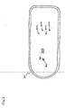
- FIG. 2 is a top view of the bottom surface 203 of the tank 101.
- the bottom of the tank 101 is constructed with four holes 201 a-d which provide ports for establishing an air conduit between the bead diffuser 301 and the air blower assembly 701.
- FIG. 2 illustrates the use of four holes 201 a-d in a staggered position on the bottom of the tank 101, it should be evident to someone skilled in the art that different arrangements and numbers of connecting ports may be used without departing from the scope of the i invention. In another preferred embodiment, as shown in FIGs.
- a fifth hole 202 is used to provide a communication port between a temperature probe 305 located within the tank 101, and a microprocessor-based system adapted to correspondingly increase or decrease the temperature of the pressurized air flowing through the beads 303.
- the temperature of the beads 303 is continuously monitored by the probe 305 which operably signals the heating and cooling system to adjust the air temperature as is necessary to maintain patient comfort.
- a temperature probe 305 can be positioned within the air conduit or the air blower assembly, it is preferable to position the temperature probe within the tank 101 to provide a temperature reading which more accurately reflects the temperature of the patient support surface.
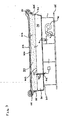
- a preferred embodiment of the present invention comprises an inflatable bead diffuser 301 which rest against the bottom surface 203 of the tank 101.
- the inflated bead diffuser 301 provides an upper diffuser surface 310 which is elevated relative to the generally horizontal bottom surface 203 of the tank 101.
- a fluidized patient support surface is formed by a quantity of fluidization material 303 supported on top of the normally inflated bead diffuser 301.
- the bead diffuser 301 when in an inflated condition increases the height of the fluidized patient support surface relative to the bottom surface 203 of the tank 101.
- an inflatable bead diffuser 301 therefore provides the means for significantly reducing the quantity of fluidization material 303 required to form a fluidized patient support surface.
- the bead diffuser 301 is initially placed into the tank 101 in a deflated condition, and an air blower assembly 701 provides the necessary flow of air to inflate the bead diffuser 301 and fluidize a quantity of material 303 supported thereon.
- the inflatable bead diffuser 301 is assembled with four air nozzles 501 a-d specially designed to insert into four fluidization ports 302 a-d which are set into four holes 201 a-d constructed on the bottom of the tank 101.
- An air conduit is provided between the bead diffuser 301 and the air blower assembly 701 using flexible air hoses 308 a-d attached at a first end to the air blower assembly 701 and a second end to the fluidization ports 302 a-d.
- a flow of inflation and fluidization air generated by the air blower 701 flows through the air hoses 308 a-d to the attached fluidization ports 302 a-d and into the bead diffuser 301 through the air nozzles 501 a-d releasably inserted into the fluidization ports 302 a-d.
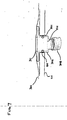
- a preferred air nozzle 501 is integrally attached to the bottom surface 311 of the bead diffuser 301 .
- an air nozzle 501 is coupled to the bottom surface 311 of the bead diffuser 301 by first inserting the air nozzle 501 through the air holes cut into two disk shaped swathes of fabric material 602 a-b .
- the fabric disk 602 a-b are preferably constructed of a "REGENCY" fabric, which is a high strength laminated nylon taffeta fabric manufactured in China and distributed in U.S.A. by John C. Tucker Co., Inc.
- Another fabric disk 604 having a center air hole is then placed on the top surface of the circular head 608 of the air nozzle 501.
- the top fabric disk 604 is also preferably constructed of REGENCY. Using conventional sewing techniques, the fabric disks 602 a-b and 604 are sewn together to securely fasten the circular head 608 of the air nozzle 501 within a three layer fabric disk 605.
- the air nozzle 501 is then inserted through a hole cut into the bottom surface 311 of the bead diffuser 301. When so positioned, the air nozzle 501 projects out of the bead diffuser 301, and the circular head 608 contained within the three-layer fabric disk 605 rest against the bottom surface 311 of the bead diffuser 301.
- the circular patch 603 preferably includes an adhesive surface 607 which adheres the patch 603 to the top surface of the fabric disk 605, and to the bottom surface 311 of the bead diffuser 301. As illustrated in FIG.
- the perimeter 606 of the circular patch 603 is greater than the perimeter of the fabric disk 605 so that when the patch 603 is adhered to the bottom surface 311 of the bead diffuser 301, the fabric disk 605 is securely fastened between the patch 603 and the bottom surface 311 of the bead diffuser 301.
- the circular patch 603 forms an air-tight seal which prevents any air-loss between the circular head 608 of the air nozzle 501 and the bottom surface 311 of the bead diffuser 301.
- a relatively gas-tight fit between the air nozzle 501 and the corresponding fluidization port 302 is provided by an "O" ring seal 601 which occupies a groove fabricated into the neck of the air nozzle 501.
- the fluidization material 303 is contained within a bead pouch 307 that is supported on top of the inflatable bead diffuser 301.
- the bead, pouch 307 is preferably an integral component of the inflatable bead diffuser 301, however, the bead pouch 307 can be separately assembled without departing from the scope of the present invention.
- the fluidization material preferably consists of medical grade silicone spherical beads 303 of the type commonly employed in air fluidized bead support systems. Such beads 303 generally comprise a soda-lime core encased within a silicone sphere, and range in size from 50 to 150 microns in diameter. As can be appreciated from FIG.
- the diffuser surface 310 of the inflatable bead diffuser 301 is integral to the bottom bead support surface 309 of the bead pouch 307.
- the side walls of the bead pouch 307 are formed by attaching one edge of a fabric skirt 304 to the outer perimeter 314 of the top diffuser surface 310 of the bead diffuser 301, and attaching the second edge of the fabric skirt 304 to the tank rim 105.
- the fabric skirt 304 frames the outer perimeter 314 of the top diffuser surface 310 of the bead diffuser 301, and forms the side walls of the pouch 307 for containing the fluidization material therein.
- the top surface of the bead pouch 307 is formed by placing a bottom filter sheet 306 over the top of the beads 303 contained within the side walls of the fabric skirt 304, and attaching the peripheral edges of the filter sheet 306 to the tank rim 105.
- a second top filter sheet 313 is then placed over the bottom filter sheet 306, draped over the tank rim 105, and attached along the outer tank wall.
- the pressurized air flowing through the inflatable bead diffuser 301 vents through the bottom surface 309 of the bead pouch 307 and fluidizes the quantity of beads 303 contained within the pouch 307.
- bead pouch 307 to contain the beads 303 therein
- alternative bead pouch 307 arrangements may be constructed without departing from the scope of the invention.
- a plurality of adjacently attached bead pouches can be transversely positioned across the top of the bead diffuser 301 to provide a suitable fluidized patient support surface.
- a bead diffuser 301 is constructed of an inflatable material that is distendable upon receiving pressurized air from a pressurized air source.
- the flow of pressurized air into the bead diffuser 301 forms a plenum space 315 between the bottom surface 203 of the tank 101, and the quantity of beads 303 supported on top of the bead diffuser 301.
- inflation of the plenum space 315 elevates the diffuser surface 310 relative to the bottom surface 203 of the tank 101.
- this embodiment of the presently disclosed fluidized bead bed 100 provides several significant advantages over the prior art.
- elevating the diffuser surface 310 is desirable because it significantly reduces the quantity of beads 303 necessary to form a fluidized patient support surface.
- This reduction in the quantity of beads 303 substantially decreases the weight of the fluidized bead bed 100 over that of prior fluidization patient support systems.
- conventional fluidized patient support systems may weigh in excess of 2,000 pounds; however, the presently preferred fluidized bead bed 100 weighs less than 1,000 pounds.
- the inflatable bead diffuser 301 functions as an air mattress to prevent the undesirable effects associated with what is known in the art as "patient bottoming out.”
- an occupant of a fluidized support system may sink through the fluidized beads 303 to the tank bottom 203.
- This "bottoming out” effect may result in a patient being lacerated by system components located on the bottom of the tank, such as rivets, bolts, and/or systems probes.
- system components located on the bottom of the tank, such as rivets, bolts, and/or systems probes.
- the patient would merely come to rest on top of an inflated bead diffuser 301 and not the tank bottom 203.
- the presently disclosed inflatable bead diffuser 301 therefore provides cushioned support to patients who experience "bottoming out”.
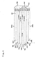
- FIGS. 4 and 5 illustrate a bottom and cross sectional view of a preferred bead diffuser 301, respectively.
- the outer perimeter of the bead diffuser 301 is specially designed to be substantially similar to the inner perimeter of the tank 101 ( FIG. 2 ).
- the side surfaces 312 a-b of a normally inflated bead diffuser 301 fit tightly against the inner wall of the tank 101. This sealed fit prevents any portion of the bead pouch 307 and beads 303 contained therein from sliding down between the inner walls of the tank 101 and the bead diffuser 301.
- the bead diffuser 301 forms an inflatable enclosure having a substantially rectangular body with a circular head end 403 and a squared foot end 404.
- the air nozzles 501 a-d are integrally coupled to the bottom surface 311 of the bead diffuser 301 so as to properly align with the air holes 201a-d located on the bottom of the tank 101 ( FIG. 2 ).
- another opening 401 is provided for inserting into the bead diffuser 301 one or more transducers and/or probes for monitoring various bed functions. More particularly, such monitoring apparatus can include a temperature probe 305, a pressure transducer and/or a distance sensing transducer operable to determine how far a patient is depressed into the bead diffuser 301.
- FIG. 5 shows a cross sectional view of a preferred bead diffuser 301 in a substantially inflated form.
- an inflatable bead diffuser 301 comprises nine inflatable air chambers 502 a-i adjacently positioned to at least one other air chamber.
- each inflatable air chamber 502 a-i extends longitudinally the entire length of the bead diffuser 301.
- At least a portion of the upper surface of each inflatable air chamber 502 a-i is comprised of a fabric material specially adapted to facilitate the flow of pressurized air out of the inflated bead diffuser 301 at a rate sufficient to fluidize a quantity of fluidization material resting against the upper surface of the bead diffuser 301.
- the upper surface of the bead diffuser 301 is therefore operable as a diffuser surface 310.
- the top diffuser surface 310 of each inflatable air chamber 502 a-i is preferably constructed from a high-airloss nylon mesh weave fabric such as that commercially available from W.L. Gore & Associates under the trademark "GORE-TEX.”
- the diffuser surface 310 can be assembled using low-airloss fabric material in which the fabric includes a multiplicity of air apertures that channel the flow of fluidization air out of the bead diffuser 301.
- Such a diffuser surface 310 can be fabricated by using a standard industrial sewing machine, without spooled thread, to needle the apertures into the low-airloss GORE-TEX fabric material. It should be understood by those skilled in the art, however, that alternative diffuser surfaces and means for fabricating such diffuser surfaces can be used without departing from the scope of the invention.
- the bottom surface 311 and side surfaces 312 a-b of the bead diffuser 301 are made of a low or no air-loss fabric material.
- the pressurized air within the bead diffuser 301 does not flow out through the bottom surface 311 and side surfaces 312 a-b, but is forced upwardly through the diffuser surface 310.
- a suitable, no air-loss fabric material for assembling the bottom surface 311 and side surfaces 312 a-b is a polyurethane-backed nylon fabric material commercially available under the trademark "K-KOTE.”
- K-KOTE a low air-loss GORE-TEX fabric material can be used to construct the side surfaces 312 a-b .
- the fabric skirt 304 is assembled using either no air-loss K-KOTE or low air-loss GORE-TEX to prevent fluidization air from escaping between the fabric skirt 304 and the inner wall of the tank 101.
- each inflatable air chamber 502 a-i has at least one side wall formed by an air baffle 402 a-h , respectively.
- the air baffles 402 a-h serve primarily to prevent bowing of the inflatable air chambers 502 a-i, and to support the upwardly flow of fluidization air through the diffuser surface 310.
- Each air baffle is preferably made of a low air-loss GORE-TEX fabric material having an upper edge that is attached to at least a portion of the diffuser surface 310, and a lower edge attached to at least a portion of the bottom surface 311 of the bead diffuser 301.
- each air baffle 402 a-h is sewn to the respective surfaces, 310 and 311, using conventional sewing techniques.
- the bottom surface 311 and side surfaces 312 a-b be substantially air-tight to prevent a reduction in the flow of fluidization pressure through the diffuser surface 311. Therefore, where baffles 402a-h are attached to either the bottom surface 311 and/or side surface 312 a-b, it is a preferred that the air baffle be assembled using welding or heat-sealing techniques which form an air-tight seal at the respective site of attachment. It should be understood by those skilled in the art that alternative methods of forming a relatively air-tight seal between the air baffle and the attachment surface can be used without departing from the scope of the invention.
- each air baffle 402 a-h is not attached to the head end 403 or leg end 404 of the bead diffuser 301.
- This preferred assembly provides air passages 405 at the ends of each air baffle 402 a-h which allows the fluidization air to flow into each chamber 502 a-i .
- pressurized air flowing through the air nozzles 501 a-d and into the bead diffuser 301 is able to equalize throughout the bead diffuser 301 by flowing through the air passages 405.
- Air passages (not shown) can also be provided for by placing air openings at various locations along the length of each air baffle 402 a-h.
- a preferred bead diffuser 301 is specially designed such that a cross sectional profile of the bead diffuser 301 discloses a concave shaped diffuser surface 310. More specifically, the inflatable chambers 502 a-i of the bead diffuser 301 form a trough which extends lengthwise along the upper diffuser surface 310. As shown, the two outer inflatable chambers (502a and 502i) are specially designed to form an upper diffuser surface 310 which is elevated relative to the diffuser surface 310 defined by the three inner inflatable chambers (502 d-f ).
- a preferred assembly for forming a concave shaped bead diffuser 301 includes fabricating air baffles 402 a-h with differing heights, whereby the air baffles forming the side walls of the outer inflatable chambers are of a greater height relative to the air baffles forming the side walls of the inner most inflatable chambers.
- a concave shaped diffuser surface 310 is highly advantageous in that the quantity of fluidization material required to form a fluidized patient support surface is further reduced as compared to a substantially horizontal diffuser surface. More particularly, the fluidized material situated nearest to the tank wall normally forms the patient support surface for supporting the patient's extremities. As the patient's extremities normally weigh less than the patient's body, less fluidization material is generally required to support the patient's extremities.
- a preferred bead diffuser 301 comprising upright inflatable chambers ( 502a and 502i ) effectively reduces the quantity of beads 303 needed to form the patient support surface which supports the patient's extremities:
- the inner inflatable chambers 502 e-f are specially designed to form a diffuser surface 310 which is more distal to the fluidized patient support surface and is, therefore, able to support the greater quantity of fluidization material generally required for supporting the heavier head, torso, and leg portions of the patient's body.
- a diffuser surface 310 can be variously shaped without departing from the scope of the present invention.
- the diffuser surface 310 could simply define a horizontal surface.
- FIG. 8 An exploded view of a preferred air blower assembly 701 for supplying a flow of air through the diffuser surface 310 at a rate sufficient to fluidize the beads 303 supported thereon is illustrated in FIG. 8 .
- the air blower assembly 701 is housed within a framed box that occupies and is conveniently removed from within the' foot pedestal 103.
- the framed box 705 is set upon a pair of front wheels 702 and rear wheels 703 (not shown) to provide the user with convenient access to the air blower assembly 701.
- the foot end cover 704 of the foot pedestal 103 is removed, and the framed box 705 is simply rolled out of the foot pedestal 103.
- a hinged top cover 718 is easily lifted to reveal the individual components of the air blower assembly 701.
- the side walls and supporting, surfaces of the framed box 705, and the head and foot pedestals (102-103) are fabricated out of a light-weight composite material to further reduce the overall weight of the fluidized bead bed 100.
- a preferred air blower assembly 701 comprises two electric motor driven air blowers 709 a-b which supply a flow of pressurized air sufficient to inflate the bead diffuser 301 and fluidize the fluidization material 303 supported thereon.
- the air blowers 709 a-b are preferrably variable speed type blowers which provide for adjustments in the air flow rate so as to enable the bed user to selectively alter the level of fluidization.
- room air is initially filtered through two air filters 708 a-b before entering the air blowers 709 a-b through air connection ports 719 (not shown).
- Pressurized air is channeled out of the air blowers 709 a-b through discharge ports 720 a-b and into discharge hoses 716 a-b which provide an air conduit between the air blowers 709 a-b and a heat exchanger 711.
- three exhaust fans 717 are provided which function to draw heat away from the air blower assembly 701.
- a preferred heat exchanger 711 includes a heating element 721 (not shown) which is operable to maintain the temperature of the pressurized air within a preferred range of about 26.7 °C to 37.7 °C (80 to 100 degrees Fahrenheit).
- a furnace filter 714 is also provided to clean the air used to cool the heat exchanger 711.
- Pressurized air is discharged from within the heat exchanger 711 into four flexible air hoses 308 a-d which provide air conduits between the heat exchanger 711 and the bead diffuser 301. In this manner, pressurized air flows through the flexible air hoses 308 a-d and into the bead diffuser 301 which becomes inflated and fluidizes the beads 303 supported thereon. The fluidization air is then exhausted through the bottom 306 and top 313 filter sheets which are permeable to air but not to the beads 303.
- At least one of the four flexible air hoses 308 a-d is in fluid communication with one or more auxiliary air hoses 713 a-b via a valve assembly 712.
- air flowing through the air hose 308d can be diverted by the valve assembly 712 and into two auxiliary air hoses 713 a-b for the purpose of providing pressurized air to an inflatable patient support system (not shown), or other system requiring pressurized air for proper operation.
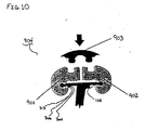
- FIGs. 10 and 11 A preferred embodiment for attaching the fabric skirt 304, the bottom filter sheet 306 and the top filter sheet 313 to the tank rim 105 are illustrated in FIGs. 10 and 11 .
- three strips (1001, 1002, and 1003) of a hook or loop fabric material is attached to the tank rim 105.
- a hook or loop fabric is well known in the art, and is commercially available under the trade mark "VELCRO”.
- An opposing hook or loop VELCRO strip for adhering to the strips attached to the tank rim 105 is secured to the perimeter edge of the fabric skirt 304, the bottom filter sheet 306 and the top filter sheet 313. As shown in FIG.
- the bead pouch 307 is formed within the tank 101 by extending the fabric skirt 304 upward along the inner wall of the tank 101 and attaching the VELCRO strip on the perimeter of the fabric skirt 304 to the first strip 1001 of VELCRO extending about the inner edge of the tank rim 105.
- the upper surface of the bead pouch 307 is formed by attaching the VELCRO strip on the bottom filter sheet 306 to a second VELCRO strip 1003 positioned about the outer edge of the tank rim 105.
- attaching the fabric skirt 304, and the bottom filter sheet 306 to the tank rim 105 forms the preferred bead pouch 307.
- both prevention of patient injury and attachment of the respective sheets 304, 305 and 313 is accomplished using a three piece flexible bumper assembly 904 to overlap the rigid tank rim 105.
- an inner perimeter bumper 901 is placed over the attached sheets (304, 305 and 313), and securely fastened to the inner perimeter of the tank rim 105.
- a corresponding outer perimeter bumper 902 is fastened to the outer perimeter of the tank rim 105.
- a middle perimeter bumper 903 is used to demountably engage the inner 901 and outer 902 perimeter bumpers and, thus, secure the bumper assembly 904 to the tank rim 105.
- a top cover sheet 106 is fitted over the bumper 904 to form a preferred patient support surface.
- FIG. 12 illustrates a control panel 109 which serves as the primary interface for controlling and adjusting the functions of the presently disclosed fluidized bead bed 100.
- the control panel 109 is shown extending from the foot pedestal 102.
- the control panel 109 can be stored out of view and in a closed position within the foot pedestal 102.
- fluidization of the beads 303 is activated or deactivated by switching the ON/OFF switch 1101 to its respective ON or OFF position.
- the ON light 1105 is illuminated as long as the ON/OFF switch 1101 remains in an ON position.
- the air flow adjustment 1102 is used to increase or decrease the flow of fluidization air into the bead diffuser 301 and up through the beads 303 supported thereon.
- fluidization may be suspended without deflation of the bead diffuser 301. This embodiment allows the patient to remain accessible on top of the inflated bead diffuser 301 even though fluidization is suspended.
- a temperature adjustment 1103 is provided which enables the care giver or patient to increase or decrease the temperature of the fluidization air flowing through the beads 303 and out the patient support surface. It is preferable that the temperature of the beads 303 be adjustable between the range of 26.7 °C (80 degrees Fahrenheit) at the minimum setting, and 37.7 °C (100 degrees Fahrenheit) at the maximum setting. Illumination of the heat light 1107 or cool light 1106 verifies that the system is either heating or cooling the beads 303 as selected.
- the patient is provided with a hand control 110 to control the bed 100 fluidization functions (not shown).
- the main control panel 109 is equipped with a fluidization lock-out switch 1104 to prevent fluidization from being inadvertently activated or deactivated from the hand control 110.
- the fluidization locked out light 1108 illuminates when this control function is activated.
- FIG. 13 shows a substantially inflated bead diffuser 301 comprising three separately inflated chambers (1300 a-c ) which define a foot section 1301a, a torso section 1301b, and a head section 1301c.
- each chamber 1300 a-c is in fluid communication with at least one air blower assembly 701 via three flexible air hoses 308 a-c , as described above (not shown).
- each chamber 1300a-c is assembled with integral air nozzles 501 a-c which insert into fluidization ports 302 located on the bottom of the tank 101.
- the fluidization ports 302 are positioned in such a manner as to properly align with the air nozzles 501 a-c when the bead diffuser 301 is positioned against the bottom surface 203 of the tank 101.
- the rate of air flowing into each chamber 1300 a-c can be regulated so as to enable the bed user to adjust the fluidization of the beads 303 immediately above each chamber 1300 a-c .
- This selective fluidization can be accomplished by placing each chamber 1300 a-c in fluid communication with distinct variable speed air blowers, or by providing one or more adjustable air valves operable to increase or decrease the flow of air from the air source to each respective chamber 1300 a-c .
- fluidization of the beads 303 corresponding to each section 1301 a-c of the patient's body can be increased or decreased as is necessary to form an adequate fluidized patient support surface.
- a patient torso section which may be significantly heavier relative to the head and leg portions of a patient's body can be provided with greater support by merely decreasing the fluidization pressure within the torso section 1301 b of the bead diffuser 301.
- Separate air blowers and/or air valves can be individually actuated from either the control panel 109 or hand control 110 to adjust the fluidization above the respective section 1301 a-c.
- the bead diffuser chamber 1300c described above can be raised or lowered to elevate a patient resting on top of the fluidized patient support surface.
- an inflatable air bladder 1401 in a substantially inflated form is shown positioned between the bead diffuser chamber 1300 c of the bead diffuser 301, and the bottom surface 203 of the tank 101.
- an air source provides pressurized air through an air conduit connected to the inflatable air bladder 1401 (not shown).
- the fluidized patient support surface positioned above the head section 1301c is preferably formed using a multiplicity of adjacently attached bead pouches 1402 a-d transversely positioned on top of the bead diffuser 301.
Landscapes
- Health & Medical Sciences (AREA)
- Nursing (AREA)
- Life Sciences & Earth Sciences (AREA)
- Animal Behavior & Ethology (AREA)
- General Health & Medical Sciences (AREA)
- Public Health (AREA)
- Veterinary Medicine (AREA)
- Invalid Beds And Related Equipment (AREA)
- Devices And Processes Conducted In The Presence Of Fluids And Solid Particles (AREA)
- Heat Treatment Of Strip Materials And Filament Materials (AREA)
- Heating, Cooling, Or Curing Plastics Or The Like In General (AREA)
- Percussion Or Vibration Massage (AREA)
Claims (14)
- Bett mit fluidisierten Kügelchen (100), welches umfasst:eine offene Wanne (101);einen aufgeblasenen Kügelchendiffusor (301), der in der Wanne (101) platziert ist, wobei der Diffusor (301) eine nicht-starre Schicht umfasst;fluidizierbare Kügelchen (303), die über dem Diffusor (301) in der Wanne (101) platziert sind;eine poröse Abdeckfolie (106), die an der Wanne (101) befestigt ist, sodass die Kügelchen (303) sich zwischen dem Diffusor (301) und der Folie in der Wanne (101) befinden und die Folie (106) eine Oberfläche zur Aufnahme eines Patienten umfasst; undLuftzuführmittel (701), die einen unter dem Diffusor (301) definierten ausgefüllten Raum (315) in der Wanne (101) operativ aufblasen, der ermöglicht, dass Luft daraus austritt, um die Kügelchen (303) zu fluidisieren,dadurch gekennzeichnet, dass der Diffusor (301) mehrere aufblasbare Kammern (502 a-i) umfasst.
- Bett (100) nach Anspruch 1, dadurch gekennzeichnet, dass das Bett (100) auch eine Überwachungseinrichtung zur Überwachung wenigstens einer Funktion des Bettes (100) umfasst.
- Bett nach Anspruch 2, dadurch gekennzeichnet, dass die Überwachungseinrichtung ein System auf Mikroprozessorbasis umfasst.
- Bett nach Anspruch 2 oder Anspruch 3, dadurch gekennzeichnet, dass die Überwachungseinrichtung eine Temperatursonde in der Wanne (101) umfasst.
- Bett nach einem der Ansprüche 2 bis 4, dadurch gekennzeichnet, dass die Überwachungseinrichtung auch einen Messwandler umfasst, um zu bestimmen, wie weit ein Patient in den Kügelchendiffusor (301) eingesunken ist.
- Bett (100) nach einem der vorangehenden Ansprüche, dadurch gekennzeichnet, dass die Abdeckfolie (106) PTFE umfasst.
- Bett (100) nach einem der vorangehenden Ansprüche, dadurch gekennzeichnet, dass die Kügelchen (303) in einem Kügelchenbeutel (307) enthalten sind.
- Bett nach einem der vorangehenden Ansprüche, dadurch gekennzeichnet, dass die Kügelchen (303) einen Natronkalk-Kern umfassen, der in einer Silizium-Kugel eingeschlossen ist, und von etwa 50 bis etwa 150 Mikrons im Durchmesser reichen.
- Bett (100) nach einem der vorangehenden Ansprüche, dadurch gekennzeichnet, dass die Fluidisierungsluft durch die Oberfläche zur Aufnahme des Patienten abgegeben wird.
- Bett (100) nach einem der vorangehenden Ansprüche, dadurch gekennzeichnet, dass jede der Kammern (502 a-i) benachbart zu wenigstens einer anderen der Kammern (502 a-i) ist.
- Bett nach einem der vorangehenden Ansprüche, dadurch gekennzeichnet, dass jede der Kammern (502) wenigstens eine Seitenwand umfasst, die eine Ablenkwand (402) umfasst.
- Bett (100) nach einem der vorangehenden Ansprüche, dadurch gekennzeichnet, dass der Diffusor (301) eine konkave Querschnittsform aufweist.
- Bett (100) nach einem der vorangehenden Ansprüche, dadurch gekennzeichnet, dass die Luftzuführmittel (701) ein Gebläse mit variabler Geschwindigkeit umfassen.
- Bett (100) nach einem der vorangehenden Ansprüche, dadurch gekennzeichnet, dass die aufblasbare Luftkammern (502) auf mehrere Drücke aufgeblasen werden können.
Applications Claiming Priority (3)
| Application Number | Priority Date | Filing Date | Title |
|---|---|---|---|
| US12692999P | 1999-03-29 | 1999-03-29 | |
| US126929P | 1999-03-29 | ||
| PCT/US2000/008376 WO2000057830A1 (en) | 1999-03-29 | 2000-03-29 | Fluidized bead bed with inflatable bead diffuser |
Publications (3)
| Publication Number | Publication Date |
|---|---|
| EP1139966A1 EP1139966A1 (de) | 2001-10-10 |
| EP1139966A4 EP1139966A4 (de) | 2006-05-17 |
| EP1139966B1 true EP1139966B1 (de) | 2008-05-14 |
Family
ID=22427428
Family Applications (1)
| Application Number | Title | Priority Date | Filing Date |
|---|---|---|---|
| EP00918499A Expired - Lifetime EP1139966B1 (de) | 1999-03-29 | 2000-03-29 | Bett mit fluidisierten kügelchen und aufblasbarem diffusor |
Country Status (4)
| Country | Link |
|---|---|
| EP (1) | EP1139966B1 (de) |
| AT (1) | ATE395026T1 (de) |
| DE (1) | DE60038870D1 (de) |
| WO (1) | WO2000057830A1 (de) |
Cited By (1)
| Publication number | Priority date | Publication date | Assignee | Title |
|---|---|---|---|---|
| US10238560B2 (en) | 2013-03-13 | 2019-03-26 | Hill-Rom Services, Inc. | Air fluidized therapy bed having pulmonary therapy |
Families Citing this family (1)
| Publication number | Priority date | Publication date | Assignee | Title |
|---|---|---|---|---|
| US9700239B2 (en) * | 2012-07-06 | 2017-07-11 | Hill-Rom Services, Inc. | Fluidizable bed with occupancy status detection and method of occupancy status detection for a fluidizable bed |
Family Cites Families (24)
| Publication number | Priority date | Publication date | Assignee | Title |
|---|---|---|---|---|
| US3428973A (en) * | 1966-03-17 | 1969-02-25 | Thomas S Hargest | Fluidized supporting apparatus |
| US3866606A (en) * | 1973-09-04 | 1975-02-18 | Thomas S Hargest | Cyclically produced contoured support |
| US4483029A (en) * | 1981-08-10 | 1984-11-20 | Support Systems International, Inc. | Fluidized supporting apparatus |
| JPS5884133U (ja) * | 1981-12-01 | 1983-06-07 | 富士電機株式会社 | 固体粒子媒体を流動化して用いる医療用ベツド |
| US4425676A (en) * | 1982-03-09 | 1984-01-17 | Crane Robert L | Cushion to reduce the incidence of decubitus ulcers in immobilized patients |
| FR2523841B1 (fr) * | 1982-03-25 | 1985-10-25 | Lacoste Francois | Lit fluidise a usage therapeutique |
| JPS59218152A (ja) * | 1983-05-27 | 1984-12-08 | 富士電機株式会社 | 流動ベツドのかたさ制御装置 |
| JPS60116351A (ja) * | 1983-11-30 | 1985-06-22 | 富士電機株式会社 | ビ−ズ流動式身体支持装置 |
| US4609854A (en) * | 1985-02-01 | 1986-09-02 | Fuji Electric Company Ltd. | Control device for a hospital bed |
| US4637083A (en) * | 1985-03-13 | 1987-01-20 | Support Systems International, Inc. | Fluidized patient support apparatus |
| JPS61290953A (ja) * | 1985-06-19 | 1986-12-20 | 富士電機株式会社 | 身体支持具 |
| US4642825A (en) * | 1985-07-08 | 1987-02-17 | Fuji Electric Co., Ltd. | Control apparatus for clinic bed |
| US4723328A (en) * | 1985-07-30 | 1988-02-09 | Fuji Electric Co., Ltd. | Fluidized bead bed |
| US4686723A (en) * | 1985-11-14 | 1987-08-18 | The University Of Toronto Innovations Foundation | Semi-fluidized bed |
| NL8702712A (nl) * | 1987-11-12 | 1989-06-01 | Caremedic Bv | Bed voor therapeutische behandeling van een patient. |
| US4835802A (en) * | 1988-02-22 | 1989-06-06 | The Kmw Group, Inc. | Fluidization patient support control system |
| NL8800792A (nl) * | 1988-03-29 | 1989-10-16 | Redactron Bv | Werkwijze en inrichting voor het onttrekken van vocht aan een of meer lichamen. |
| US5008965A (en) | 1988-07-11 | 1991-04-23 | Kinetic Concepts, Inc. | Fluidized bead bed |
| US4967431A (en) * | 1988-12-20 | 1990-11-06 | SSI Medical Servies, Inc. | Fluidized bed with modular fluidizable portion |
| US4942635A (en) * | 1988-12-20 | 1990-07-24 | Ssi Medical Services, Inc. | Dual mode patient support system |
| US4914760A (en) * | 1988-12-20 | 1990-04-10 | Ssi Medical Services, Inc. | Fluidized bed with collapsible side |
| US5402542A (en) * | 1993-04-22 | 1995-04-04 | Ssi Medical Services, Inc. | Fluidized patient support with improved temperature control |
| US5539943A (en) * | 1994-03-08 | 1996-07-30 | Ssi Medical Services, Inc. | Apparatus and method for percussion of fluidized support surface |
| US6016581A (en) * | 1997-06-27 | 2000-01-25 | Miki; Sakae | Semi-fluid mattress |
-
2000
- 2000-03-29 AT AT00918499T patent/ATE395026T1/de active
- 2000-03-29 DE DE60038870T patent/DE60038870D1/de not_active Expired - Lifetime
- 2000-03-29 EP EP00918499A patent/EP1139966B1/de not_active Expired - Lifetime
- 2000-03-29 WO PCT/US2000/008376 patent/WO2000057830A1/en not_active Ceased
Cited By (1)
| Publication number | Priority date | Publication date | Assignee | Title |
|---|---|---|---|---|
| US10238560B2 (en) | 2013-03-13 | 2019-03-26 | Hill-Rom Services, Inc. | Air fluidized therapy bed having pulmonary therapy |
Also Published As
| Publication number | Publication date |
|---|---|
| EP1139966A4 (de) | 2006-05-17 |
| WO2000057830A1 (en) | 2000-10-05 |
| ATE395026T1 (de) | 2008-05-15 |
| DE60038870D1 (de) | 2008-06-26 |
| EP1139966A1 (de) | 2001-10-10 |
Similar Documents
| Publication | Publication Date | Title |
|---|---|---|
| EP1901635B1 (de) | Patientenliege | |
| EP0569058B1 (de) | Patientenliegevorrichtung | |
| US4967431A (en) | Fluidized bed with modular fluidizable portion | |
| US5623736A (en) | Modular inflatable/air fluidized bed | |
| EP1024733B1 (de) | Matratze mit luftwirbelschichtkammern | |
| US5029352A (en) | Dual support surface patient support | |
| US10092470B2 (en) | Patient lifter with intraoperative controlled temperature air delivery system | |
| US5168589A (en) | Pressure reduction air mattress and overlay | |
| US8146191B2 (en) | Patient support | |
| HK1007951B (en) | Patient support systems | |
| WO1990000381A1 (en) | Improved fluidized bead bed | |
| CA2316461C (en) | Coverlet for an air bed | |
| US7779496B2 (en) | Air mattress for bed with step deck | |
| EP1139966A1 (de) | Bett mitt fluidisierten kügelchen und aufblasbaren diffusor | |
| AU2012202878B2 (en) | Patient support | |
| MXPA00003749A (en) | Mattress having air fluidized sections |
Legal Events
| Date | Code | Title | Description |
|---|---|---|---|
| PUAI | Public reference made under article 153(3) epc to a published international application that has entered the european phase |
Free format text: ORIGINAL CODE: 0009012 |
|
| 17P | Request for examination filed |
Effective date: 20010621 |
|
| AK | Designated contracting states |
Kind code of ref document: A1 Designated state(s): AT BE CH CY DE DK ES FI FR GB GR IE IT LI LU MC NL PT SE |
|
| A4 | Supplementary search report drawn up and despatched |
Effective date: 20060403 |
|
| 17Q | First examination report despatched |
Effective date: 20061207 |
|
| GRAP | Despatch of communication of intention to grant a patent |
Free format text: ORIGINAL CODE: EPIDOSNIGR1 |
|
| RAP1 | Party data changed (applicant data changed or rights of an application transferred) |
Owner name: KCI LICENSING, INC. |
|
| GRAS | Grant fee paid |
Free format text: ORIGINAL CODE: EPIDOSNIGR3 |
|
| GRAA | (expected) grant |
Free format text: ORIGINAL CODE: 0009210 |
|
| AK | Designated contracting states |
Kind code of ref document: B1 Designated state(s): AT BE CH CY DE DK ES FI FR GB GR IE IT LI LU MC NL PT SE |
|
| REG | Reference to a national code |
Ref country code: GB Ref legal event code: FG4D |
|
| REG | Reference to a national code |
Ref country code: CH Ref legal event code: EP |
|
| REG | Reference to a national code |
Ref country code: IE Ref legal event code: FG4D Free format text: LANGUAGE OF EP DOCUMENT: FRENCH |
|
| REF | Corresponds to: |
Ref document number: 60038870 Country of ref document: DE Date of ref document: 20080626 Kind code of ref document: P |
|
| PG25 | Lapsed in a contracting state [announced via postgrant information from national office to epo] |
Ref country code: FI Free format text: LAPSE BECAUSE OF FAILURE TO SUBMIT A TRANSLATION OF THE DESCRIPTION OR TO PAY THE FEE WITHIN THE PRESCRIBED TIME-LIMIT Effective date: 20080514 Ref country code: ES Free format text: LAPSE BECAUSE OF FAILURE TO SUBMIT A TRANSLATION OF THE DESCRIPTION OR TO PAY THE FEE WITHIN THE PRESCRIBED TIME-LIMIT Effective date: 20080825 |
|
| NLV1 | Nl: lapsed or annulled due to failure to fulfill the requirements of art. 29p and 29m of the patents act | ||
| PG25 | Lapsed in a contracting state [announced via postgrant information from national office to epo] |
Ref country code: NL Free format text: LAPSE BECAUSE OF FAILURE TO SUBMIT A TRANSLATION OF THE DESCRIPTION OR TO PAY THE FEE WITHIN THE PRESCRIBED TIME-LIMIT Effective date: 20080514 |
|
| PG25 | Lapsed in a contracting state [announced via postgrant information from national office to epo] |
Ref country code: SE Free format text: LAPSE BECAUSE OF FAILURE TO SUBMIT A TRANSLATION OF THE DESCRIPTION OR TO PAY THE FEE WITHIN THE PRESCRIBED TIME-LIMIT Effective date: 20080814 Ref country code: PT Free format text: LAPSE BECAUSE OF FAILURE TO SUBMIT A TRANSLATION OF THE DESCRIPTION OR TO PAY THE FEE WITHIN THE PRESCRIBED TIME-LIMIT Effective date: 20081014 Ref country code: DK Free format text: LAPSE BECAUSE OF FAILURE TO SUBMIT A TRANSLATION OF THE DESCRIPTION OR TO PAY THE FEE WITHIN THE PRESCRIBED TIME-LIMIT Effective date: 20080514 |
|
| PG25 | Lapsed in a contracting state [announced via postgrant information from national office to epo] |
Ref country code: BE Free format text: LAPSE BECAUSE OF FAILURE TO SUBMIT A TRANSLATION OF THE DESCRIPTION OR TO PAY THE FEE WITHIN THE PRESCRIBED TIME-LIMIT Effective date: 20080514 |
|
| PLBE | No opposition filed within time limit |
Free format text: ORIGINAL CODE: 0009261 |
|
| STAA | Information on the status of an ep patent application or granted ep patent |
Free format text: STATUS: NO OPPOSITION FILED WITHIN TIME LIMIT |
|
| 26N | No opposition filed |
Effective date: 20090217 |
|
| PG25 | Lapsed in a contracting state [announced via postgrant information from national office to epo] |
Ref country code: MC Free format text: LAPSE BECAUSE OF NON-PAYMENT OF DUE FEES Effective date: 20090331 |
|
| REG | Reference to a national code |
Ref country code: CH Ref legal event code: PL |
|
| PG25 | Lapsed in a contracting state [announced via postgrant information from national office to epo] |
Ref country code: CH Free format text: LAPSE BECAUSE OF NON-PAYMENT OF DUE FEES Effective date: 20090331 Ref country code: LI Free format text: LAPSE BECAUSE OF NON-PAYMENT OF DUE FEES Effective date: 20090331 |
|
| PG25 | Lapsed in a contracting state [announced via postgrant information from national office to epo] |
Ref country code: GR Free format text: LAPSE BECAUSE OF FAILURE TO SUBMIT A TRANSLATION OF THE DESCRIPTION OR TO PAY THE FEE WITHIN THE PRESCRIBED TIME-LIMIT Effective date: 20080815 |
|
| PG25 | Lapsed in a contracting state [announced via postgrant information from national office to epo] |
Ref country code: LU Free format text: LAPSE BECAUSE OF NON-PAYMENT OF DUE FEES Effective date: 20090329 |
|
| PG25 | Lapsed in a contracting state [announced via postgrant information from national office to epo] |
Ref country code: CY Free format text: LAPSE BECAUSE OF FAILURE TO SUBMIT A TRANSLATION OF THE DESCRIPTION OR TO PAY THE FEE WITHIN THE PRESCRIBED TIME-LIMIT Effective date: 20080514 |
|
| REG | Reference to a national code |
Ref country code: GB Ref legal event code: 732E Free format text: REGISTERED BETWEEN 20130502 AND 20130508 |
|
| PGFP | Annual fee paid to national office [announced via postgrant information from national office to epo] |
Ref country code: GB Payment date: 20140424 Year of fee payment: 15 Ref country code: IE Payment date: 20140416 Year of fee payment: 15 |
|
| PGFP | Annual fee paid to national office [announced via postgrant information from national office to epo] |
Ref country code: IT Payment date: 20140424 Year of fee payment: 15 Ref country code: FR Payment date: 20140430 Year of fee payment: 15 Ref country code: DE Payment date: 20140423 Year of fee payment: 15 Ref country code: AT Payment date: 20140430 Year of fee payment: 15 |
|
| REG | Reference to a national code |
Ref country code: DE Ref legal event code: R119 Ref document number: 60038870 Country of ref document: DE |
|
| REG | Reference to a national code |
Ref country code: AT Ref legal event code: MM01 Ref document number: 395026 Country of ref document: AT Kind code of ref document: T Effective date: 20150329 |
|
| GBPC | Gb: european patent ceased through non-payment of renewal fee |
Effective date: 20150329 |
|
| PG25 | Lapsed in a contracting state [announced via postgrant information from national office to epo] |
Ref country code: IT Free format text: LAPSE BECAUSE OF NON-PAYMENT OF DUE FEES Effective date: 20150329 |
|
| REG | Reference to a national code |
Ref country code: FR Ref legal event code: ST Effective date: 20151130 |
|
| REG | Reference to a national code |
Ref country code: IE Ref legal event code: MM4A |
|
| PG25 | Lapsed in a contracting state [announced via postgrant information from national office to epo] |
Ref country code: GB Free format text: LAPSE BECAUSE OF NON-PAYMENT OF DUE FEES Effective date: 20150329 Ref country code: DE Free format text: LAPSE BECAUSE OF NON-PAYMENT OF DUE FEES Effective date: 20151001 Ref country code: IE Free format text: LAPSE BECAUSE OF NON-PAYMENT OF DUE FEES Effective date: 20150329 |
|
| PG25 | Lapsed in a contracting state [announced via postgrant information from national office to epo] |
Ref country code: AT Free format text: LAPSE BECAUSE OF NON-PAYMENT OF DUE FEES Effective date: 20150329 Ref country code: FR Free format text: LAPSE BECAUSE OF NON-PAYMENT OF DUE FEES Effective date: 20150331 |