EP1140680B1 - Zuführvorrichtung für band aus weichem material an einer arbeitsstation - Google Patents
Zuführvorrichtung für band aus weichem material an einer arbeitsstation Download PDFInfo
- Publication number
- EP1140680B1 EP1140680B1 EP99958235A EP99958235A EP1140680B1 EP 1140680 B1 EP1140680 B1 EP 1140680B1 EP 99958235 A EP99958235 A EP 99958235A EP 99958235 A EP99958235 A EP 99958235A EP 1140680 B1 EP1140680 B1 EP 1140680B1
- Authority
- EP
- European Patent Office
- Prior art keywords
- strip
- work station
- work
- transfer deck
- transfer
- Prior art date
- Legal status (The legal status is an assumption and is not a legal conclusion. Google has not performed a legal analysis and makes no representation as to the accuracy of the status listed.)
- Expired - Lifetime
Links
- 239000000463 material Substances 0.000 title claims abstract description 31
- 238000012546 transfer Methods 0.000 claims abstract description 57
- 238000013519 translation Methods 0.000 claims abstract description 8
- 238000005520 cutting process Methods 0.000 claims description 44
- 239000004744 fabric Substances 0.000 claims description 15
- 238000006073 displacement reaction Methods 0.000 claims description 5
- 238000011144 upstream manufacturing Methods 0.000 claims description 5
- 239000000835 fiber Substances 0.000 claims description 4
- 230000000694 effects Effects 0.000 claims description 2
- 239000007921 spray Substances 0.000 claims 1
- 230000000903 blocking effect Effects 0.000 abstract 1
- 230000003100 immobilizing effect Effects 0.000 description 6
- 238000000034 method Methods 0.000 description 3
- 238000004519 manufacturing process Methods 0.000 description 2
- 241000897276 Termes Species 0.000 description 1
- 230000002860 competitive effect Effects 0.000 description 1
- 238000011161 development Methods 0.000 description 1
- 239000006260 foam Substances 0.000 description 1
- 238000003698 laser cutting Methods 0.000 description 1
- 238000005259 measurement Methods 0.000 description 1
- 238000006386 neutralization reaction Methods 0.000 description 1
- 229920002994 synthetic fiber Polymers 0.000 description 1
- 238000012549 training Methods 0.000 description 1
Images


Classifications
-
- B—PERFORMING OPERATIONS; TRANSPORTING
- B65—CONVEYING; PACKING; STORING; HANDLING THIN OR FILAMENTARY MATERIAL
- B65H—HANDLING THIN OR FILAMENTARY MATERIAL, e.g. SHEETS, WEBS, CABLES
- B65H20/00—Advancing webs
- B65H20/16—Advancing webs by web-gripping means, e.g. grippers, clips
- B65H20/18—Advancing webs by web-gripping means, e.g. grippers, clips to effect step-by-step advancement of web
-
- B—PERFORMING OPERATIONS; TRANSPORTING
- B65—CONVEYING; PACKING; STORING; HANDLING THIN OR FILAMENTARY MATERIAL
- B65H—HANDLING THIN OR FILAMENTARY MATERIAL, e.g. SHEETS, WEBS, CABLES
- B65H2301/00—Handling processes for sheets or webs
- B65H2301/50—Auxiliary process performed during handling process
- B65H2301/51—Modifying a characteristic of handled material
- B65H2301/512—Changing form of handled material
- B65H2301/5125—Restoring form
- B65H2301/51254—Unshirring
Definitions
- the present invention relates to the field of devices supply of flexible material, for example unrolled from a coil, to power a workstation.
- document EP 0 860 249 presents a method and a device intended for cutting a sheet of material positioned on a cutting table.
- document DE A36 10 551 describes a device of known type allowing the pinching and advancement of a strip of synthetic material.
- the object of the present invention is to remedy these drawbacks by proposing a device capable of supplying flexible strip material with a workstation, and to have said strip on the workstation of so as to allow its treatment under optimal conditions, including tension to remove the folds from the strip.
- the present invention allows the supply of multi-layer strip mattresses from a cutting station. Clothes for clean rooms require, for reasons of protection and hygiene in particular, important precautions during manufacturing. After the individual cutting of each pattern, known methods carry out in several operations the assembly comprising an overcasting, that is to say a seam along the cutting to fix the fibers of the edges, and a double flap to trap them definitely.
- the present invention overcomes these problems by realizing the supply, then the simultaneous cutting, of a fabric mattress comprising different layers of material (for tracksuits intended for clean rooms) via a laser beam.
- the supply device of a flexible strip work station unrolled from a reel comprising a transfer plate, driven by a movement of translation of longitudinal horizontal axis, by means movement, between a first loading position of the tape of material and a second so-called working position, said plate transfer comprising first means capable of immobilizing the strip on said plate when moving the latter from the position of loading to that of work, is characterized in that the plate of transfer is able to support on its surface the strip, and in that the work station includes second immobilization means capable of retain the free end of the strip, so that the return of the plate transfer from the working position to the loading position created, by friction of the strip on said plate, forces tending to unfold the part of the strip associated with the workstation.
- the strip of flexible material is composed of several independent overlapping layers or widths of material.
- the workstation includes a work table on which is able to rest the strip of material flexible when returning the transfer plate.
- the transfer tray is located above and vertically above said work table.
- the means of movement of the transfer plate include means for guidance and training.
- the first immobilization means comprise means for pinching said strip on the plate, for example at at least one cylinder integral with said transfer plate.
- the second immobilization means consist of at least one member capable of pinching the free end of the strip on the work table.
- a development of the invention provides, upstream of the plateau of transfer, several coils of material strips whose axes are located substantially in a horizontal plane positioned slightly in below the surface of the transfer tray on which the bandage rests multilayer.
- the (or said) reel (s) of material is (are) braked.
- the advancement dimension of the strip is adjustable.
- a vapor projection ramp suitable for moisten the different layers.
- the device preferably comprises a lifting table comprising at minus a horizontal plane capable of evacuating the strip of fabric from the station job.
- the description of the device is based on an embodiment particular where the workstation is a beam cutting station laser, and where the strip is made of a material of the tissue type or not woven, foam, paper, cardboard or all materials in rolls likely to be laser cut.
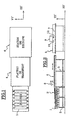
- FIG. 1 and 2 there is shown schematically in view from above and from the side the whole device, except for the table evacuation lift.
- the ground is horizontal and materialized by the plane X-X '- Y-Y'.
- a coil store 1 comprising here six coils allows, downstream, power the device.
- On each reel 1 is wound a width of one given type of fabric and the different widths 2A, 2B, 2C form independent superimposed layers which constitute a band 2.
- the axes of the coils 1 are horizontal and parallel to each other.
- a structure 3 supports the rotation shafts of the coils 1 parallel to the axis Y-Y 'and arranged in the same plane parallel to the ground.
- a transfer plate 4 Downstream of the coils 1, there is a transfer plate 4, in the form rectangular, arranged horizontally with respect to the ground. This last rests on a support 5 fixed relative to the ground and has a dimension transverse at least equal to the width of a coil 1. Said plate 4 is able to move in translation along the axis XX 'through any known means of movement (not shown). To these are associated with guide means (slides, rollers, etc.) and control means, all these means being known and not represented.
- the translational plane of the transfer plate 4 is slightly above of the horizontal plane defined by the axes of the coils 1.
- a work station 6 laser cutting downstream of the transfer plate 4 is arranged a work station 6 laser cutting.
- the latter includes a cutting table 7 horizontal, rectangular, of dimensions substantially equal to those of the plate 4 and fixed relative to the ground. Said cutting table 7 is in a plane which is slightly below that of the plateau of transfer 4 so that the latter comes to position itself, when it moves, above the cutting table 7.
- the schematic side view of Figure 2 shows the first immobilization means comprising a clamp 8, called a clamp transfer.
- a clamp transfer This is integral with the transfer plate 4 and is produced at using any known means such as for example at least two jacks arranged at the end of the transfer plate 4, on the side of the coils 1, aligned along an axis parallel to the axis Y-Y 'and spaced apart by a width slightly lower than that of the coils 1.
- the transfer clamp 8 is able to move in translation integrally of plate 4 along the axis XX 'and independently of said plate 4 following the axis Z-Z 'in order to immobilize the strip 2 of tissue on said plate 4.
- the carriage 9 comprises means 10 (known per se) capable of emitting a laser beam 11 to allow, being controlled along the axes XX 'and Y-Y ', by control means not shown and known in themselves, to cut according to the programmed pattern the strip of fabric placed on the cutting table 7.
- the laser beam 11, by cutting the strip 2 produces a micro burn different layers, preventing the appearance of fibers at the edges.
- the garment obtained is therefore more reliable and more competitive since in one single operation, the invention simultaneously provides, cutting and neutralization of fibers on the edge of layers superimposed on the strip 2 of fabrics.
- a second immobilization means such as a clamp 12 holding able to immobilize the strip 2 of tissue on their entire width, on the cutting table 7; the clamp 12 is described later.
- Figures 3a, 3b, 3c, 3d and 3e represent, in schematic view of side, the respective positions of the device of the invention during a cycle of operation.
- Initialization is carried out manually by the operator. This step consists in successively bringing each width of fabrics forming the strip 2 up to the end of the transfer plate 4. For this, he pulls the fabric from each spool 1, passes it under the clamp 8 and unrolls it to the end of the transfer tray 4. thus superimposing the different fabrics from the different reels 1 on realizes a mattress placed on the plate 4.
- the transfer clamp 8 is then lowered, immobilizing the mattress on the transfer plate 4.
- the device is in the configuration shown in Figure 3a.
- the clamp 8 is lowered when it is close to the coils 1, in beginning of the cycle, so as not to damage the mattress of fabric which rests on the plate 4.
- the holding clip 12 is in the raised position when the plate 4 begins to move in translation, as the shows Figure 3b, through actuators provided for this purpose (not shown).
- the transfer of the plate 4 to the cutting station 6 achieves, upstream of plate 4, the simultaneous unwinding of the different widths of the strip 2.
- the advancement rating of the transfer plate 4 can be arbitrary and therefore match the length of fabric only necessary.
- the transfer clamp 8 can then be raised and the transfer plate 4 does the opposite as shown in Figure 3d.
- the mattress being immobilized at its end on the cutting table 7, the return of the plate 4 then realizes, by means of friction force, the unfolding of the future mattress which will be, during the next cycle, on the set of transfer 4.
- the transfer clamp 8 is lowered then the clamp holding 12 raised, as shown in FIG. 3e.
- the part of the mattress which then rests on the cutting table 7 can be treated by the laser beam 11.
- the strip 2 is cut according to one or several patterns before being separated from the next mattress by a cutting over the entire width of the strip 2.
- a variant consists in first isolate the mattress placed on the cutting table 7 by cutting it over its entire width, the next mattress being ready for a new cycle.
- Figures 4a and 4b show, in cross-sectional views, the details of the means of pinching the strip 2 on the cutting table 7, by the holding clip 12.
- the mattress is held on the transfer plate 4 by the clamp transfer 8 (not shown).
- the plate 4 is brought above the cutting table 7 at the desired advancement dimension.
- the progress rating corresponds to the maximum dimension, i.e. at the end of the cutting table 7.
- the transfer plate 4 comes to a standstill and the clamp support 12 is lowered in order to block the mattress on the table cutout 7.
- a spatula 13 is added by any known means to the end of the transfer plate 4 and at least one recess 14 is made on the edge of said spatula 13 facing downstream.
- the spatula 13 has an inclination downstream which allows the mattress of fabric not to undergo too much tension break on the edge downstream of the transfer plate 4.
- the strip 2 is gradually brought closer to the cutting table 7 from the surface of the transfer table 4 supporting the strip.
- the holding clamp 12 pinches the mattress on the cutting table 7 passing through the recess 14 of the spatula 13.
- the strip 2 of fabrics is then fixed relative to the cutting table 7 and the transfer plate 4 can return to the initial loading position.
- FIG. 5 shows, seen from above, the detail of spatula 13 in a shape particular embodiment where the holding clip 12 consists of four cylinders distributed over the width of the cutting table 7.
- Four recesses 14 arranged opposite these jacks are provided on the spatula 13 in order to achieve a substantially uniform pinching of the strip 2 on the cutting table 7.
- the spatula 13 is generally rectangular in shape and its dimension transverse corresponds to the transverse dimension of the transfer 4.
- the spatula 13 being attached to the transfer plate 4, in its extension along the axis XX ′, its thickness is substantially identical to that of said transfer plate 4.
- the second immobilization means are fixed relative to the cutting table 7.
- said clamp holding 12 is independent of the transverse carriage 9 and the dimension advancement of the transfer plate 4 is no longer adjustable.
- the holding clip 12 can be fixed to the downstream end of the cutting table 7, the advancement dimension then being maximum.
Landscapes
- Treatment Of Fiber Materials (AREA)
- Adhesive Tape Dispensing Devices (AREA)
- Advancing Webs (AREA)
- Electroplating Methods And Accessories (AREA)
- Replacement Of Web Rolls (AREA)
- Auxiliary Devices For And Details Of Packaging Control (AREA)
- Automobile Manufacture Line, Endless Track Vehicle, Trailer (AREA)
- Sewing Machines And Sewing (AREA)
- Manufacturing Of Electric Cables (AREA)
Claims (13)
- Zuführvorrichtung für Band aus weichem Material (2) an einer Arbeitsstation (6), das von einer Spule (1) abgerollt wird, mit einer Transferplatte (4) mit einer Schubbewegung durch eine horizontale Längsachse mittels Verschiebeeinrichtungen zwischen einer ersten Beschickungsposition für Band aus weichem Material (2) und einer zweiten, sogenannten Arbeitsposition, wobei die Transferplatte (4) erste Einrichtungen besitzt, die das Band während der Verschiebung der Platte von der Beschickungsposition in die Arbeitsposition auf der Platte festhalten können, dadurch gekennzeichnet, dass die Transferplatte (4) das Band aus weichem Material (2) auf ihrer Fläche aufnehmen kann, und dass die Arbeitsstation (6) zweite Immobilisierungseinrichtungen besitzt, die das freie Ende des Bandes auf der sogenannten Arbeitsstation (6) so festhalten können, dass durch die Rückkehr der Transferplatte (4) von der Arbeitsposition in die Beschickungsposition durch Reibung des Bandes (2) auf der Platte Kräfte entstehen, die den Teil des Bandes, der mit der Arbeitsstation (6) verbunden ist, auseinanderziehen.
- Vorrichtung nach Anspruch 1, dadurch gekennzeichnet, dass das Band aus weichem Material (2) aus mehreren einzelnen, übereinandergelagerten Materialschichten oder Material-Maschinenbreiten besteht.
- Vorrichtung nach einem der vorhergehenden Ansprüche 1 oder 2, dadurch gekennzeichnet, dass die Arbeitsstation (6) einen Arbeitstisch (7) besitzt, auf dem das Band aus weichem Material (2) während der Rückkehr der Transferplatte verbleiben kann.
- Vorrichtung nach den vorhergehenden Ansprüchen 1 bis 3, dadurch gekennzeichnet, dass sich die Transferplatte (4) über dem und senkrecht zum Arbeitstisch (7) befindet, wenn sie sich in Arbeitsposition befindet.
- Vorrichtung nach einem der vorhergehenden Ansprüche, dadurch gekennzeichnet, dass die Verschiebeeinrichtungen der Transferplatte (4) Führungseinrichtungen und Antriebe besitzen.
- Vorrichtung nach einem der vorhergehenden Ansprüche, dadurch gekennzeichnet, dass die ersten Immobilisierungseinrichtungen Klemmvorrichtungen für das Band (2) an der Platte (4) besitzen.
- Vorrichtung nach einem der vorhergehenden Ansprüche, dadurch gekennzeichnet, dass die zweiten Immobilisierungseinrichtungen aus mindestens einem Element bestehen, mit dem das freie Ende des Bandes (2) auf dem Arbeitstisch (7) eingeklemmt werden kann.
- Vorrichtung nach Anspruch 2, dadurch gekennzeichnet, dass vor der Transferplatte (4) mehrere Material-Spulen (1) vorgesehen sind, deren Achsen sich weitgehend in einer Horizontalebene befinden, die etwas unterhalb der Fläche der Transferplatte (4), auf der sich das mehrschichtige Band (2) befindet, liegt.
- Vorrichtung nach Anspruch 8, dadurch gekennzeichnet, dass die Material- Spule(n) (1) gebremst ist (sind).
- Vorrichtung nach einem der vorhergehenden Ansprüche, dadurch gekennzeichnet, dass das Vorschubmaß der Transferplatte (4) verstellbar ist.
- Vorrichtung nach Anspruch 2, dadurch gekennzeichnet, dass eine Dampfsprührampe zum Befeuchten der verschiedenen Schichten vorgesehen ist, damit sie nicht aneinanderhaften.
- Vorrichtung nach einem der vorhergehenden Ansprüche, dadurch gekennzeichnet, dass sie einen Hubtisch besitzt, der mindestens eine Horizontalebene aufweist, auf der das Band (2) verbleiben kann, wobei der Tisch das Stoffband von der Arbeitsstation (6) austragen kann.
- Schneidvorrichtung für das weiche Material wie Stoffband (2) mit einer Zuführvorrichtung einer Arbeitsstation (6) gemäß einer der vorhergehenden Ansprüche, dadurch gekennzeichnet, dass das Band (2) aus mehreren, einzelnen, übereinandergelagerten Materialschichten besteht, und dass sie außerdem eine Schneidvorrichtung mit Vorrichtungen zum Aussenden eines Laserstrahls (11) und Verschiebeeinrichtungen für die genannten Laserstrahl-Aussendevorrichtungen entlang einer horizontalen Längsachse und einer horizontalen Querachse, die im Verhältnis zur Arbeitsstation (6) senkrecht zu letzterer verläuft, besitzt, so dass der Laserstrahl (11) beim Durchtrennen des Bandes (2) eine Mikroverbrennung der verschiedenen Schichten durchführt, um so zu verhindern, dass an den Rändern Fasern auftreten.
Applications Claiming Priority (3)
| Application Number | Priority Date | Filing Date | Title |
|---|---|---|---|
| FR9815835 | 1998-12-15 | ||
| FR9815835A FR2787098B1 (fr) | 1998-12-15 | 1998-12-15 | Dispositif d'approvisionnement en bande de materiau souple d'une station de travail |
| PCT/FR1999/002996 WO2000035794A1 (fr) | 1998-12-15 | 1999-12-02 | Dispositif d'approvisionnement en bande de materiau souple d'une station de travail |
Publications (2)
| Publication Number | Publication Date |
|---|---|
| EP1140680A1 EP1140680A1 (de) | 2001-10-10 |
| EP1140680B1 true EP1140680B1 (de) | 2003-06-04 |
Family
ID=9533999
Family Applications (1)
| Application Number | Title | Priority Date | Filing Date |
|---|---|---|---|
| EP99958235A Expired - Lifetime EP1140680B1 (de) | 1998-12-15 | 1999-12-02 | Zuführvorrichtung für band aus weichem material an einer arbeitsstation |
Country Status (7)
| Country | Link |
|---|---|
| US (1) | US6624381B1 (de) |
| EP (1) | EP1140680B1 (de) |
| AT (1) | ATE242167T1 (de) |
| AU (1) | AU1564700A (de) |
| DE (1) | DE69908647T2 (de) |
| FR (1) | FR2787098B1 (de) |
| WO (1) | WO2000035794A1 (de) |
Cited By (1)
| Publication number | Priority date | Publication date | Assignee | Title |
|---|---|---|---|---|
| CN111164249A (zh) * | 2017-08-01 | 2020-05-15 | 林道尔·多尼尔有限责任公司 | 用于将幅面形的产品由织机拉出的装置 |
Families Citing this family (7)
| Publication number | Priority date | Publication date | Assignee | Title |
|---|---|---|---|---|
| ES2856349T3 (es) * | 2017-11-23 | 2021-09-27 | Dallan Spa | Aparato para el corte por láser o por plasma de piezas de material laminar enrollado en bobina |
| EP3699304B1 (de) * | 2019-02-19 | 2022-09-14 | Comelz S.p.A. | Vorrichtung zum verbesserten halten und schneiden von flächengebilde |
| EP3699302A1 (de) * | 2019-02-19 | 2020-08-26 | Comelz S.p.A. | Blattmaterialschneidevorrichtung |
| EP3699305B1 (de) * | 2019-02-19 | 2024-12-04 | Comelz S.p.A. | Numerische steuerungsvorrichtung zum automatisierten schneiden eines materialbogens oder mehrerer übereinanderliegender bögen |
| EP3699303A1 (de) * | 2019-02-19 | 2020-08-26 | Comelz S.p.A. | Zusatzvorrichtung zur erleichterung der zufuhr von in cnc-maschinen zu schneidenden materialbögen |
| CN111037120A (zh) * | 2020-01-09 | 2020-04-21 | 深圳市泽诚自动化设备有限公司 | 一种激光切割机 |
| CN114311756B (zh) * | 2022-03-15 | 2022-05-17 | 常州江苏大学工程技术研究院 | 一种风电叶片主梁纤维布铺放装置 |
Family Cites Families (9)
| Publication number | Priority date | Publication date | Assignee | Title |
|---|---|---|---|---|
| DE384136C (de) | 1922-11-05 | 1923-11-03 | Bayerischer Bergaerar Vertrete | Doppelt wirkende Stampfmaschine mit mehreren in zwei Gruppen unterteilten Stampfern |
| DE507733C (de) | 1929-01-06 | 1930-09-19 | Linke Hofmann Busch Werke Akt | Verbindung des abgefederten Fahrgestells eines Gleiskettenfahrzeuges mit den Gleiskettenfuehrungsrahmen |
| GB1239406A (de) * | 1967-09-21 | 1971-07-14 | ||
| FR2172530A5 (en) * | 1972-02-16 | 1973-09-28 | Etienne Francine | Film transport mechanism - using a single motor for synchronised transfer, welding and cutting operations |
| JPS5915551A (ja) * | 1982-07-16 | 1984-01-26 | 株式会社山東鉄工所 | 高熱液噴射ノズル |
| DE3610551A1 (de) * | 1985-11-11 | 1987-05-14 | Kiefel Hochfrequenz Paul | Einrichtung zum herstellen von aus kunststoffolienbahnen gebildeten nutzen |
| DE3905192A1 (de) * | 1989-02-21 | 1990-08-30 | Aristo Graphic Systeme | Automatisch gesteuerte vorrichtung fuer die abschnittsweise behandlung einer bahn aus flachmaterial |
| EP0507733A1 (de) * | 1991-04-03 | 1992-10-07 | Ciba-Geigy Ag | Vorrichtung zum Schneiden und Stapeln von Bögen |
| US5727433A (en) * | 1995-09-08 | 1998-03-17 | Gerber Garment Technology, Inc. | Method for cutting sheet material |
-
1998
- 1998-12-15 FR FR9815835A patent/FR2787098B1/fr not_active Expired - Fee Related
-
1999
- 1999-12-02 AU AU15647/00A patent/AU1564700A/en not_active Abandoned
- 1999-12-02 AT AT99958235T patent/ATE242167T1/de not_active IP Right Cessation
- 1999-12-02 WO PCT/FR1999/002996 patent/WO2000035794A1/fr not_active Ceased
- 1999-12-02 US US09/856,509 patent/US6624381B1/en not_active Expired - Fee Related
- 1999-12-02 EP EP99958235A patent/EP1140680B1/de not_active Expired - Lifetime
- 1999-12-02 DE DE69908647T patent/DE69908647T2/de not_active Expired - Fee Related
Cited By (2)
| Publication number | Priority date | Publication date | Assignee | Title |
|---|---|---|---|---|
| CN111164249A (zh) * | 2017-08-01 | 2020-05-15 | 林道尔·多尼尔有限责任公司 | 用于将幅面形的产品由织机拉出的装置 |
| CN111164249B (zh) * | 2017-08-01 | 2022-03-01 | 林道尔·多尼尔有限责任公司 | 用于将幅面形的产品从织机拉出的装置 |
Also Published As
| Publication number | Publication date |
|---|---|
| FR2787098B1 (fr) | 2001-06-22 |
| WO2000035794A1 (fr) | 2000-06-22 |
| EP1140680A1 (de) | 2001-10-10 |
| DE69908647D1 (de) | 2003-07-10 |
| FR2787098A1 (fr) | 2000-06-16 |
| AU1564700A (en) | 2000-07-03 |
| US6624381B1 (en) | 2003-09-23 |
| ATE242167T1 (de) | 2003-06-15 |
| DE69908647T2 (de) | 2004-04-29 |
Similar Documents
| Publication | Publication Date | Title |
|---|---|---|
| EP3248920B1 (de) | Verfahren zum abschneiden und herstellen einer stossverbindung zwischen zwei bändern und zum stoppen einer abwickelmaschine, abschneide- und verbindungsvorrichtung und maschine, die mit einer solchen vorrichtung ausgestattet ist, die die umsetzung dieses verfahrens ermöglicht | |
| FR2586238A1 (fr) | Procede de manutention de feuilles souples | |
| FR2591932A1 (fr) | Systeme de decoupage a laser | |
| FR2623176A1 (fr) | Appareillage et procede pour traiter la partie d'extremite d'une feuille de papier en rouleau disposee en un emplacement de raccordement | |
| FR2501628A1 (fr) | Procede et dispositif pour ouvrir et charger des recipients flexibles | |
| FR2535355A1 (fr) | Procede et dispositif de chargement de feuilles et etiqueteuse pour machine a decouper automatique | |
| FR2676427A1 (fr) | Procede et dispositif de bobinage d'une bande de film. | |
| EP1140680A1 (de) | Zuführvorrichtung für band aus weichem material an einer arbeitsstation | |
| EP0741096B1 (de) | Transportvorrichtung für metallisiertes Bahnmaterial | |
| FR2765191A1 (fr) | Procede et machine de collage automatique d'un film plastique thermoretractable sur le fond d'une caisse ouverte | |
| EP0622168B1 (de) | Verfahren und Vorrichtung zum Verkleben eines Kantenschutzklebebandes auf dem Rand einer mehrschichtigen Verbundplatte, wie eine Wärmeschutzplatte eines Raumfahrzeuges | |
| FR2484979A1 (fr) | Procede et appareil d'assemblage de matiere en feuille, notamment pour alimenter en continu des imprimantes rapides | |
| EP0200604A2 (de) | Stofflegemaschine | |
| FR2670130A1 (fr) | Procede et dispositif de fabrication de faisceaux de fibres creuses semi-permeables pour appareil a membrane. | |
| FR2620073A1 (fr) | Machine pour la decoupe de pieces dans une bande de matiere et pour la jonction des pieces qui viennent d'etre decoupees | |
| WO1988003580A1 (fr) | Machine de pliage d'articles textiles | |
| EP0252844B1 (de) | Automatische Vorrichtung zum Bearbeiten, insbesondere zum Schneiden von Bändern | |
| EP0004631B1 (de) | Verpackungsvorrichtung und -verfahren | |
| EP0119938A1 (de) | Maschine zum Behandeln und Präparieren von Bändern, insbesondere Bandagen, nach ihrer Herstellung | |
| EP0726835B1 (de) | Verfahren und vorrichtung zum vermindern der nutzoberfläche einer zuschneidmaschine | |
| EP0900737A1 (de) | Vorrichtung zum Aufbringen und Perforieren eines biegsamen Versteifungs- und/oder Führungsbandes, Verfahren und auf diese Weise hergestellter Verpackungsbehälter | |
| EP0239484A1 (de) | Verfahren und Vorrichtung zum Positionieren von Stoff auf einem Schneidetisch | |
| EP1037843B1 (de) | Verfahren zum schneiden von plaketten sowie vorrichtung zur durchführung des verfahrens | |
| CH359593A (fr) | Dispositif permettant d'intercepter en cours de distribution des feuilles déposées une à une en pile | |
| WO1987005472A1 (fr) | Procede et dispositif de mise en place de tissu sur une table de decoupe |
Legal Events
| Date | Code | Title | Description |
|---|---|---|---|
| PUAI | Public reference made under article 153(3) epc to a published international application that has entered the european phase |
Free format text: ORIGINAL CODE: 0009012 |
|
| 17P | Request for examination filed |
Effective date: 20010613 |
|
| AK | Designated contracting states |
Kind code of ref document: A1 Designated state(s): AT BE CH CY DE DK ES FI FR GB GR IE IT LI LU MC NL PT SE |
|
| GRAH | Despatch of communication of intention to grant a patent |
Free format text: ORIGINAL CODE: EPIDOS IGRA |
|
| GRAH | Despatch of communication of intention to grant a patent |
Free format text: ORIGINAL CODE: EPIDOS IGRA |
|
| GRAA | (expected) grant |
Free format text: ORIGINAL CODE: 0009210 |
|
| AK | Designated contracting states |
Designated state(s): AT BE CH CY DE DK ES FI FR GB GR IE IT LI LU MC NL PT SE |
|
| PG25 | Lapsed in a contracting state [announced via postgrant information from national office to epo] |
Ref country code: NL Free format text: LAPSE BECAUSE OF FAILURE TO SUBMIT A TRANSLATION OF THE DESCRIPTION OR TO PAY THE FEE WITHIN THE PRESCRIBED TIME-LIMIT Effective date: 20030604 Ref country code: IT Free format text: LAPSE BECAUSE OF FAILURE TO SUBMIT A TRANSLATION OF THE DESCRIPTION OR TO PAY THE FEE WITHIN THE PRESCRIBED TIME-LIMIT;WARNING: LAPSES OF ITALIAN PATENTS WITH EFFECTIVE DATE BEFORE 2007 MAY HAVE OCCURRED AT ANY TIME BEFORE 2007. THE CORRECT EFFECTIVE DATE MAY BE DIFFERENT FROM THE ONE RECORDED. Effective date: 20030604 Ref country code: IE Free format text: LAPSE BECAUSE OF FAILURE TO SUBMIT A TRANSLATION OF THE DESCRIPTION OR TO PAY THE FEE WITHIN THE PRESCRIBED TIME-LIMIT Effective date: 20030604 Ref country code: GB Free format text: LAPSE BECAUSE OF FAILURE TO SUBMIT A TRANSLATION OF THE DESCRIPTION OR TO PAY THE FEE WITHIN THE PRESCRIBED TIME-LIMIT Effective date: 20030604 Ref country code: FI Free format text: LAPSE BECAUSE OF FAILURE TO SUBMIT A TRANSLATION OF THE DESCRIPTION OR TO PAY THE FEE WITHIN THE PRESCRIBED TIME-LIMIT Effective date: 20030604 |
|
| REG | Reference to a national code |
Ref country code: GB Ref legal event code: FG4D Free format text: NOT ENGLISH |
|
| REG | Reference to a national code |
Ref country code: CH Ref legal event code: EP |
|
| REG | Reference to a national code |
Ref country code: IE Ref legal event code: FG4D Free format text: FRENCH |
|
| REF | Corresponds to: |
Ref document number: 69908647 Country of ref document: DE Date of ref document: 20030710 Kind code of ref document: P |
|
| PG25 | Lapsed in a contracting state [announced via postgrant information from national office to epo] |
Ref country code: SE Free format text: LAPSE BECAUSE OF FAILURE TO SUBMIT A TRANSLATION OF THE DESCRIPTION OR TO PAY THE FEE WITHIN THE PRESCRIBED TIME-LIMIT Effective date: 20030904 Ref country code: PT Free format text: LAPSE BECAUSE OF FAILURE TO SUBMIT A TRANSLATION OF THE DESCRIPTION OR TO PAY THE FEE WITHIN THE PRESCRIBED TIME-LIMIT Effective date: 20030904 Ref country code: GR Free format text: LAPSE BECAUSE OF FAILURE TO SUBMIT A TRANSLATION OF THE DESCRIPTION OR TO PAY THE FEE WITHIN THE PRESCRIBED TIME-LIMIT Effective date: 20030904 Ref country code: DK Free format text: LAPSE BECAUSE OF FAILURE TO SUBMIT A TRANSLATION OF THE DESCRIPTION OR TO PAY THE FEE WITHIN THE PRESCRIBED TIME-LIMIT Effective date: 20030904 |
|
| PG25 | Lapsed in a contracting state [announced via postgrant information from national office to epo] |
Ref country code: ES Free format text: LAPSE BECAUSE OF FAILURE TO SUBMIT A TRANSLATION OF THE DESCRIPTION OR TO PAY THE FEE WITHIN THE PRESCRIBED TIME-LIMIT Effective date: 20030915 |
|
| REG | Reference to a national code |
Ref country code: CH Ref legal event code: NV Representative=s name: INFOSUISSE INFORMATION HORLOGERE ET INDUSTRIELLE |
|
| NLV1 | Nl: lapsed or annulled due to failure to fulfill the requirements of art. 29p and 29m of the patents act | ||
| PG25 | Lapsed in a contracting state [announced via postgrant information from national office to epo] |
Ref country code: CY Free format text: LAPSE BECAUSE OF FAILURE TO SUBMIT A TRANSLATION OF THE DESCRIPTION OR TO PAY THE FEE WITHIN THE PRESCRIBED TIME-LIMIT Effective date: 20031202 |
|
| GBV | Gb: ep patent (uk) treated as always having been void in accordance with gb section 77(7)/1977 [no translation filed] |
Effective date: 20030604 |
|
| PGFP | Annual fee paid to national office [announced via postgrant information from national office to epo] |
Ref country code: CH Payment date: 20031210 Year of fee payment: 5 |
|
| PGFP | Annual fee paid to national office [announced via postgrant information from national office to epo] |
Ref country code: MC Payment date: 20031211 Year of fee payment: 5 |
|
| PGFP | Annual fee paid to national office [announced via postgrant information from national office to epo] |
Ref country code: AT Payment date: 20031222 Year of fee payment: 5 |
|
| PGFP | Annual fee paid to national office [announced via postgrant information from national office to epo] |
Ref country code: LU Payment date: 20031229 Year of fee payment: 5 |
|
| REG | Reference to a national code |
Ref country code: IE Ref legal event code: FD4D |
|
| PGFP | Annual fee paid to national office [announced via postgrant information from national office to epo] |
Ref country code: BE Payment date: 20040212 Year of fee payment: 5 |
|
| PGFP | Annual fee paid to national office [announced via postgrant information from national office to epo] |
Ref country code: DE Payment date: 20040217 Year of fee payment: 5 |
|
| PLBE | No opposition filed within time limit |
Free format text: ORIGINAL CODE: 0009261 |
|
| STAA | Information on the status of an ep patent application or granted ep patent |
Free format text: STATUS: NO OPPOSITION FILED WITHIN TIME LIMIT |
|
| 26N | No opposition filed |
Effective date: 20040305 |
|
| PG25 | Lapsed in a contracting state [announced via postgrant information from national office to epo] |
Ref country code: LU Free format text: LAPSE BECAUSE OF NON-PAYMENT OF DUE FEES Effective date: 20041202 Ref country code: AT Free format text: LAPSE BECAUSE OF NON-PAYMENT OF DUE FEES Effective date: 20041202 |
|
| PGFP | Annual fee paid to national office [announced via postgrant information from national office to epo] |
Ref country code: FR Payment date: 20041230 Year of fee payment: 6 |
|
| PG25 | Lapsed in a contracting state [announced via postgrant information from national office to epo] |
Ref country code: MC Free format text: LAPSE BECAUSE OF NON-PAYMENT OF DUE FEES Effective date: 20041231 Ref country code: LI Free format text: LAPSE BECAUSE OF NON-PAYMENT OF DUE FEES Effective date: 20041231 Ref country code: CH Free format text: LAPSE BECAUSE OF NON-PAYMENT OF DUE FEES Effective date: 20041231 Ref country code: BE Free format text: LAPSE BECAUSE OF NON-PAYMENT OF DUE FEES Effective date: 20041231 |
|
| BERE | Be: lapsed |
Owner name: S.A. *MANUFACTURE DE LINGE DE MAISON Effective date: 20041231 |
|
| PG25 | Lapsed in a contracting state [announced via postgrant information from national office to epo] |
Ref country code: DE Free format text: LAPSE BECAUSE OF NON-PAYMENT OF DUE FEES Effective date: 20050701 |
|
| REG | Reference to a national code |
Ref country code: CH Ref legal event code: PL |
|
| PG25 | Lapsed in a contracting state [announced via postgrant information from national office to epo] |
Ref country code: FR Free format text: LAPSE BECAUSE OF NON-PAYMENT OF DUE FEES Effective date: 20060831 |
|
| REG | Reference to a national code |
Ref country code: FR Ref legal event code: ST Effective date: 20060831 |
|
| BERE | Be: lapsed |
Owner name: S.A. *MANUFACTURE DE LINGE DE MAISON Effective date: 20041231 |