EP1141423B1 - Procede de traitement par laser d'un objet en materiau a memoire de forme - Google Patents
Procede de traitement par laser d'un objet en materiau a memoire de forme Download PDFInfo
- Publication number
- EP1141423B1 EP1141423B1 EP99967929A EP99967929A EP1141423B1 EP 1141423 B1 EP1141423 B1 EP 1141423B1 EP 99967929 A EP99967929 A EP 99967929A EP 99967929 A EP99967929 A EP 99967929A EP 1141423 B1 EP1141423 B1 EP 1141423B1
- Authority
- EP
- European Patent Office
- Prior art keywords
- zone
- shape memory
- laser
- annealed
- annealing
- Prior art date
- Legal status (The legal status is an assumption and is not a legal conclusion. Google has not performed a legal analysis and makes no representation as to the accuracy of the status listed.)
- Expired - Lifetime
Links
- 238000000034 method Methods 0.000 title claims abstract description 51
- 239000012781 shape memory material Substances 0.000 title description 27
- 239000000463 material Substances 0.000 claims abstract description 46
- 230000008859 change Effects 0.000 claims abstract description 10
- 238000002425 crystallisation Methods 0.000 claims abstract description 7
- 238000001953 recrystallisation Methods 0.000 claims abstract description 4
- 238000002844 melting Methods 0.000 claims abstract 2
- 230000008018 melting Effects 0.000 claims abstract 2
- 230000003446 memory effect Effects 0.000 claims description 11
- 238000011282 treatment Methods 0.000 claims description 6
- 238000005280 amorphization Methods 0.000 claims description 4
- 230000015572 biosynthetic process Effects 0.000 claims description 4
- 239000002244 precipitate Substances 0.000 claims description 3
- 230000006870 function Effects 0.000 claims description 2
- 230000002441 reversible effect Effects 0.000 abstract description 10
- 238000010438 heat treatment Methods 0.000 abstract description 7
- 238000009877 rendering Methods 0.000 abstract 1
- 238000000137 annealing Methods 0.000 description 36
- 238000004519 manufacturing process Methods 0.000 description 28
- 230000008569 process Effects 0.000 description 26
- 229910000734 martensite Inorganic materials 0.000 description 14
- 230000009466 transformation Effects 0.000 description 13
- 238000013519 translation Methods 0.000 description 11
- 210000001367 artery Anatomy 0.000 description 10
- 239000012071 phase Substances 0.000 description 9
- 238000005224 laser annealing Methods 0.000 description 8
- 229910001285 shape-memory alloy Inorganic materials 0.000 description 8
- 229910001566 austenite Inorganic materials 0.000 description 6
- 238000001816 cooling Methods 0.000 description 5
- 239000000956 alloy Substances 0.000 description 4
- 230000008025 crystallization Effects 0.000 description 4
- 238000006073 displacement reaction Methods 0.000 description 4
- 230000000694 effects Effects 0.000 description 4
- 229910001000 nickel titanium Inorganic materials 0.000 description 4
- 229910045601 alloy Inorganic materials 0.000 description 3
- 230000008901 benefit Effects 0.000 description 3
- 239000013078 crystal Substances 0.000 description 3
- 229910052751 metal Inorganic materials 0.000 description 3
- 239000002184 metal Substances 0.000 description 3
- 210000002445 nipple Anatomy 0.000 description 3
- 230000003287 optical effect Effects 0.000 description 3
- 239000007790 solid phase Substances 0.000 description 3
- XEEYBQQBJWHFJM-UHFFFAOYSA-N Iron Chemical compound [Fe] XEEYBQQBJWHFJM-UHFFFAOYSA-N 0.000 description 2
- 229910000831 Steel Inorganic materials 0.000 description 2
- 239000006096 absorbing agent Substances 0.000 description 2
- 230000006399 behavior Effects 0.000 description 2
- 239000000919 ceramic Substances 0.000 description 2
- 230000008602 contraction Effects 0.000 description 2
- 230000007547 defect Effects 0.000 description 2
- 238000013461 design Methods 0.000 description 2
- 230000010339 dilation Effects 0.000 description 2
- 230000001747 exhibiting effect Effects 0.000 description 2
- 150000002739 metals Chemical class 0.000 description 2
- 238000002324 minimally invasive surgery Methods 0.000 description 2
- 239000013307 optical fiber Substances 0.000 description 2
- 230000002093 peripheral effect Effects 0.000 description 2
- 230000000750 progressive effect Effects 0.000 description 2
- 230000035939 shock Effects 0.000 description 2
- -1 silver ions Chemical class 0.000 description 2
- 239000010959 steel Substances 0.000 description 2
- 229910016347 CuSn Inorganic materials 0.000 description 1
- 229910002535 CuZn Inorganic materials 0.000 description 1
- CWYNVVGOOAEACU-UHFFFAOYSA-N Fe2+ Chemical compound [Fe+2] CWYNVVGOOAEACU-UHFFFAOYSA-N 0.000 description 1
- 229910000943 NiAl Inorganic materials 0.000 description 1
- NPXOKRUENSOPAO-UHFFFAOYSA-N Raney nickel Chemical compound [Al].[Ni] NPXOKRUENSOPAO-UHFFFAOYSA-N 0.000 description 1
- 229910010380 TiNi Inorganic materials 0.000 description 1
- 230000004075 alteration Effects 0.000 description 1
- 229910052782 aluminium Inorganic materials 0.000 description 1
- 238000005452 bending Methods 0.000 description 1
- 239000012620 biological material Substances 0.000 description 1
- 238000001574 biopsy Methods 0.000 description 1
- 230000017531 blood circulation Effects 0.000 description 1
- 239000000470 constituent Substances 0.000 description 1
- 229910052802 copper Inorganic materials 0.000 description 1
- 238000005258 corrosion kinetic Methods 0.000 description 1
- 230000001419 dependent effect Effects 0.000 description 1
- 229940082150 encore Drugs 0.000 description 1
- 238000010304 firing Methods 0.000 description 1
- 229910052733 gallium Inorganic materials 0.000 description 1
- 150000002500 ions Chemical class 0.000 description 1
- 229910052742 iron Inorganic materials 0.000 description 1
- 238000013532 laser treatment Methods 0.000 description 1
- 238000012423 maintenance Methods 0.000 description 1
- 239000011159 matrix material Substances 0.000 description 1
- 238000002074 melt spinning Methods 0.000 description 1
- 230000005012 migration Effects 0.000 description 1
- 238000013508 migration Methods 0.000 description 1
- 229910052758 niobium Inorganic materials 0.000 description 1
- 229910052763 palladium Inorganic materials 0.000 description 1
- 238000012545 processing Methods 0.000 description 1
- 238000010791 quenching Methods 0.000 description 1
- 230000000171 quenching effect Effects 0.000 description 1
- 238000011160 research Methods 0.000 description 1
- 229910052710 silicon Inorganic materials 0.000 description 1
- 229910052709 silver Inorganic materials 0.000 description 1
- 239000004332 silver Substances 0.000 description 1
- 239000003381 stabilizer Substances 0.000 description 1
- 239000000126 substance Substances 0.000 description 1
- 239000000758 substrate Substances 0.000 description 1
- 239000002344 surface layer Substances 0.000 description 1
- 230000000930 thermomechanical effect Effects 0.000 description 1
- 229910052718 tin Inorganic materials 0.000 description 1
- 230000007704 transition Effects 0.000 description 1
- 210000003462 vein Anatomy 0.000 description 1
Images


Classifications
-
- C—CHEMISTRY; METALLURGY
- C22—METALLURGY; FERROUS OR NON-FERROUS ALLOYS; TREATMENT OF ALLOYS OR NON-FERROUS METALS
- C22F—CHANGING THE PHYSICAL STRUCTURE OF NON-FERROUS METALS AND NON-FERROUS ALLOYS
- C22F1/00—Changing the physical structure of non-ferrous metals or alloys by heat treatment or by hot or cold working
- C22F1/006—Resulting in heat recoverable alloys with a memory effect
Definitions
- the present invention relates to a method treatment of an object in a material having a martensitic transformation, especially into a shape memory material.
- the invention applies to the manufacture of monolithic structures (that is to say monoblocks), active or passive, in shape memory materials, and in particular to the manufacture of actuators ("Actuators”), connectors, active components for fixing and grippers, monolithic, very small, made of materials with shape memory.
- monolithic structures that is to say monoblocks
- Actuators actuators
- connectors active components for fixing and grippers
- monolithic very small, made of materials with shape memory.
- phase change from a solid phase to another can be induced under duress ("Superelasticity") and / or by change of temperature (shape memory effect).
- phase change When the phase change is induced thermally, it can be accompanied by a change in macroscopic form. So a memory material of apparently plastically deformed form in its phase of low temperature, called “martensite phase”, can return to its original shape by heating up its high temperature phase, called “phase austenite ".
- the characteristic temperatures at the start and end of the austenite-martensite transformation are respectively designated by M s and M f .
- the characteristic temperatures at the start and end of the martensite-austenite transformation are respectively designated by A s and A f .
- Another known technique consists in exploit the fact that the mechanical characteristic of the material evolves with the phase change. So a mechanical assembly comprising on the one hand an element in such a material and on the other hand another element whose characteristic remains constant - will have two stable operating points corresponding to temperature and stress zones defining the solid phases of this shape memory material.
- a known technique is to create a monobloc structure which is also called structure monolithic: the actuator is then manufactured in a single and same element in shape memory material.
- the difficulty is then to be able to obtain a reversible effect and for that to obtain different mechanical properties in this same element. For this do it is necessary to locally heat this last so that only a part of it can present a shape memory effect while the other party remains passive.
- EP-A-0 086 357 A describes a process for manufacture of a housing, according to which the material of surface layers of the state housing ferritic to a substantially martensitic state.
- MIGLIORE LR "HEAT TREATING WITH LASERS” ADVANCED MATERIALS & PROCESSES, US, AMERICA SOCIETY FOR METALS, METALS PARK, OHIO, vol. 154, no. Aug 2, 1998 (1998-08-01), pages H25-H29 describes treatment with steels laser.
- FR-A-2 393 075 describes the annealing of a part made of non-ferrous metal using a laser.
- WO-A-89 10421 describes treatments of materials in shape memory alloys.
- the object of the present invention is to solve the problem of local change (i.e. at least one predefined area) of the microstructure of an object made of material capable of exhibiting an effect of memory of form.
- the present invention is defined in claim 1.
- This laser beam therefore serves to locally anneal this object by bringing the latter to a temperature T much higher than the temperature A f of the shape memory material of which the object is made.
- the temperature and annealing time are such that a amorphization of the material cannot be obtained.
- the material may even have been annealed in an oven before implement the process which is the subject of the invention.
- the local laser annealing aims to crystallize or locally recrystallize a material having a martensitic transformation (especially a shape memory material) and not of the amorphized. Amorphization by heating can be obtained when the temperature rise is very high, i.e. close to the temperature of and that the cooling is done in a way extremely fast.
- the laser therefore serves to pre-deform the object by annealing.
- the object is constrained by deformation of said object. So we do, in this case, a initial mechanical pre-deformation of the object, unlike the previous case.
- the non-irradiated part of the object can be in one piece or, on the contrary, this part not irradiated can include at least two areas that are separated by the irradiated area.
- the object is a thin element and one irradiates, by means of said laser beam, areas of this element which are distributed over said element in view to stiffen the latter.
- Figure 1 is a schematic view of a device for implementing a method according to the invention.
- a or several zones such as zone A of an object 2 in a material exhibiting a transformation martensitic, for example a memory material of form, by a laser beam 4.
- This beam 4 is suitable to bring zone A to a temperature T sufficient to crystallization, recrystallization, or secondary crystallization of this area, or the controlled formation of precipitates or the annihilation of crystal defects in this area.
- the temperature and the heating time are such that the amorphization of the material does not occur not.
- the constituent shape memory material of object 2 is a NiTi alloy for which a temperature T of the order of 500 ° C. is suitable.
- the device of Figure 1 comprises a laser 6, for example a laser diode of the kind which are marketed by Siemens under the reference S / N 150001B and whose wavelength is 810.5 nm.
- Object 2 is mounted on a positioning at three degrees of freedom which is symbolized by the perpendicular X, Y and Z axes to each other and which allows the object 2 to be placed in the laser beam 4 emitted by the diode 6.
- This laser beam is sent to zone A through, successively, a lens collimation 8, of a semi-transparent mirror 10, of a diaphragm 12 and a lens 14 for focusing the beam on the object.
- a camera 16 for example a CCD camera, is provided for observe the irradiated zone A through, successively, the lens 14, the diaphragm 12, the semi-transparent mirror 10 and optics 18.
- This camera allows you to adjust the position of the object in the laser beam 4.
- the power supply of the laser diode includes a signal generator arbitrary (not shown) to obtain laser pulses of determined power and duration.
- Figure 2 is a schematic view of a thin blade 20 of non-shape memory material annealed, for example amorphous.
- a circular area 22 of this thin blade underwent laser beam annealing according to the invention.
- Zone 24 is surrounded by zone 22 and zone 26 surrounds this zone 22.
- these zones 24 and 26 are constrained, resulting in a reversible shape memory effect and the possibility to obtain a reversible actuator.
- the area not laser annealing is not in one piece: it is formed by zones 24 and 26 which separates zone 22.
- the temperature from annealing by varying the power of the laser beam or, more generally, the energy transmitted to the object by the laser (by varying the intensity of the current diode 6 power supply in the example of Figure 1) during annealing, depending on the position of the laser spot on the object to be treated.
- the material to be shape memory annealed according to the invention can become super-elastic in the annealed area.
- the process which is the subject of the invention is therefore also usable when we want to render locally super-elastic a shape memory material.
- Figure 4 schematically illustrates a other application of the invention to stiffening a thin blade 20 of shape memory material.
- Laser annealing is carried out in points 32 of the blade 20, these points being distributed by substantially uniformly across the surface of this blade.
- Constraints are thus locally created in the blade 20 around the impact points 32 of the laser. This stiffens the blade, particularly in flexion.
- Figures 5, 6, 7, 8 and 9A, 9B illustrate schematically various devices which are likely to have very small dimensions and whose the manufacturing uses a process in accordance with the invention.
- these devices are achievable with dimensions less than 500 ⁇ m and thicknesses of the order of 1 ⁇ m to 200 ⁇ m so that we can then consider them as micro-devices.
- the device In the case of a deformation carried out after annealing (case of the example considered below), the device is free, a part (the two springs on the left in FIG. 5) is annealed; then the device is under stress and fixed.
- This deformation can be a contraction or permanent dilation, depending on laser firing parameters.
- each of the figures 5 to 8 it is a flat monolithic device whose a part is capable of undergoing a reversible movement in the plan of the device.
- the device of FIGS. 9A and 9B is a monolithic device comprising a first part which is flat and a second part which is capable of undergoing a reversible movement out of the plan of the first part.
- the element serving to the prestressing of this device is also the active element of the device while, in the case of the device of FIG. 8, the element serving for prestress the device is different from the element active of this device.
- the device of FIG. 5 is a stage of translation along an X axis.
- This device is cut by laser at from a thin blade of shape memory alloy.
- this device includes a central movable part 34, two springs 36 fixed, of a side, to this one and, on the other side, with two studs 38, two other springs 40 fixed, on one side, to the part mobile and, on the other side, to two other studs 42.
- the two springs 36 located to the left of the figure, are heated to their temperature of annealed by a laser beam in accordance with the invention.
- the two springs 40 located to the right of the figure, remain substantially at room temperature (about 20 ° C).
- the fourth springs are prestressed along the X axis (axis of translation) and the device is fixed by through the four studs on a flat substrate 44.
- the actuation principle of this device is as follows: the springs 36 are heated above the transformation temperature A s which is of the order of 60 ° C for an alloy of NiTi or NiTiCu.
- Heating can be carried out for example by an electric current that we circulate in these two springs.
- FIG. 6 is a view schematic from above is a micro-gripper which is laser cut from a thin blade of material with shape memory.
- This device comprises a fixed part 46, comprising two attachment zones 48, and a part actuator 50 intended to form a spring of reminder.
- This part actuator is connected to the fixed part 46 by through a semi-circular part 52, intended to be annealed by laser in accordance with the invention.
- a laser beam is sent on the latter.
- the gripper arm i.e. part 50 of it
- the gripper arm is then deformed outside its domain elastic in order to define the open position of this gripper.
- This device then remains open and has a certain elasticity.
- the return spring When cooling, when the part actuation returned to the martensitic state, the return spring is capable of pulling the arm in its open position.
- the device of FIG. 7 is a optical switch which is cut, for example by laser, from a thin blade of memory material amorphous.
- It includes an arm 58 intended to be move so that one of its two ends can interrupt or, on the contrary, let a light beam from an optical fiber 60.
- the element forming a spring 66 and the element 68 intended to be annealed by laser is found on either side of a line L which passes through the virtual center of rotation and which is substantially perpendicular to the arm 58.
- element 68 has elongated during its annealing.
- the Austenite form of this element 68 is thus an elongated shape.
- the shape of elements 66 and 68 can be adapted according to the desired characteristics.
- the two elements 70 are optional guide means.
- the device of FIG. 8 is formed at from a thin blade of shape memory material amorphous.
- It is an actuator comprising a fixed part 72 having substantially the shape of a frame rectangular with two sides 74 not annealed by laser while the other two sides 76 are laser annealed according to the invention.
- this device includes a part mobile 78 between the two sides 76 and this movable part is connected to the two non-annealed sides 74 respectively by an element 80 also annealed by laser according to the invention and by another element 82 not annealed forming a return spring.
- the mobile part is intended to move in translation substantially parallel to the two annealed sides 76.
- the device shown in top view in Figure 9A is cut from a thin blade made of amorphous shape memory material.
- This device comprises an arm 84, one of which end is extended by two bars 86 respectively fixed to two studs 88.
- a bar 90 is included between these two bars 86 and one of its ends is also attached to this end of the arm 84.
- the other end of the bar 80 is fixed to a stud 92.
- the device thus obtained is fixed on a planar support (not shown) via pads 88 and 92.
- the central bar 90 is then annealed by laser according to the invention.
- the deformation which can be a contraction or dilation depending on the parameters of the laser shot, as we saw above, and which is induced during annealing, causes displacement of the arm 84 out of the support plane as shown in Figure 9B which is a schematic profile view of the device after laser annealing.
- the non-annealed bars 86 form return springs that were stressed during annealing.
- the whole device is heated or only the annealed bar (for example by an element Peltier or by Joule effect or by a beam very low power laser) so as to obtain the martensitic transformation of the annealed bar 90, it deforms, which causes the whole of the arm 84.
- the annealed bar for example by an element Peltier or by Joule effect or by a beam very low power laser
- the device of FIGS. 9A and 9B can be used as an optical switch or more usually as an actuator.
- both or three movable arms of the latter then used to grasp an object.
- the present invention has other applications:
- the object treated in accordance with the invention can be a monolithic structure comprising particular areas, for example joints, and the particular areas are then irradiated by the laser beam to make these areas superelastic.
- the object is a monobloc system which is made multifunctional by the irradiation, by means of the laser beam, of various zones of this system, by transmitting, to these zones, to laser, different energies, areas being for example intended to constitute various actuators acting at different temperatures.
- the object is a monolithic structure comprising areas that it is irradiated by the laser beam at energies different to achieve a shape memory effect in some of the areas, for example to constitute actuators therefrom, and to make the other areas superelastic, by example in order to constitute joints of guidance with these other areas.
- the monobloc system in memory material of shape shown in this figure 10 includes a translation device 96 which can be compared to device of Figure 5 and which includes a table mobile 98 connected to two fixing studs 100 by through two springs 102.
- the studs are intended to be fixed to a support (not shown).
- the system further includes another device 104 intended to be fixed to the support by its two ends 106.
- This other device 104 comprises a bar mobile stabilizer 108 and elements 110 intended to form joints.
- the bar 108 is made integral with the fixed ends 106 by through some of the 110 elements and the movable table 98 via the other elements 110.
- the elements 110 for that they constitute flexible superelastic elements.
- one of the two springs 102 for example the one on the left, so that it has a shape memory effect.
- the other spring which is not annealed by the laser beam constitutes a return spring.
- the invention can be applied to any what kind of shaping materials. So she applies in particular to wires, blades, tubes, springs, flats in memory alloys of form.
- FIGS 11 to 25 illustrate schematically various particular applications of the invention.
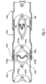
- FIG 11 is a top view in section schematic and partial of a bracelet, for example a watch strap, including serial links such as links 112, 113 and 114.
- This bracelet watch also includes fasteners ("clips") such as fasteners 115 and 116, each fastener being intended to make two adjacent links in solidarity with each other.
- fastener 115 is intended to make links 112 and 113 integral with each other and the fastener 116 is intended to make the links 113 and 114 integral one of the other.
- Each fastener which is located at the inside of one of the links is made of material shape memory and includes, in the example shown, a circular peripheral portion 117a provided with two diametrically opposed nipples 117b, intended to join the two links and a central wavy area 117c which extends substantially along the corresponding diameter nipples.
- the peripheral part 117a is provided with two diametrically opposite 117d extensions at 90 ° nipples 117b. As seen in Figure 11, these extensions have elongated holes respectively crossed by two 117th pins making it possible to make the considered attachment of one of the two corresponding links and also to guide the fastener.
- Each central area is annealed in accordance with the invention.
- this bracelet allows easily remove or add one or more links. To remove a link, simply remove two adjacent fasteners, which removes the corresponding link; then we restore the continuity of the bracelet by means of one of the two fasteners. To add a link, we remove a attachment associated with a link already present, we add the additional link, we put back the clip for make the additional link integral with the link already present and we restore the continuity of the bracelet by means of an additional clip.
- the annealed area 117c of the fastener serves then actuator to deform the elastic structure constituted by the non-annealed area, that is to say the remainder 117a, 117b, 117d of the fastener.
- this elastic structure can be inserted in a link (see attachment 116 in Figure 11) or removed of it.
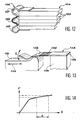
- Figure 12 is an example of fixing in local annealing shape memory material obtained by folding a sheet of uniform thickness.
- Local annealing by a process according to the invention can be used to make active or superelastic only the part forming spring.
- the zones non-annealed will be more rigid than the annealed area, which ensures good tightening.
- This fixation can for example be used to fix a stack small 123 elements such as ceramics piezoresistive.
- the stack has the reference 124, fixing to reference 126, the non-annealed areas of this fixation have the reference 127 and the annealed area has the reference 128.
- the immobilization of the stack by fixing is thermally induced.
- the properties of superelasticity in the case of a shape memory material can also be leveraged to have strength almost independent of the tolerances of the elements of stacking.
- Figure 13 shows a spring of notch commonly used in watchmaking. elasticity is given by the area annealed locally by a process according to the invention. Thanks to the properties of superelasticity (force saturation effect), we can have a notch spring with a force of maintenance little dependent on the tolerances of the object to maintain.
- the reference 130 represents a piece such as for example a crown watch which is movable in translation according to the arrow 132, the catch spring, made of material shape memory, at reference 134, the annealed area of this spring (central area) has the reference 136, the areas not annealed from this spring (end areas) have the reference 138.
- the superelasticity of area 136 is induced thermally.
- Figure 14 shows the curve of variations in the force F exerted by the spring 134 on the crown 130 as a function of the displacement ⁇ of this spring. This curve translates the mechanical behavior of the annealed zone 136. We see that F varies little over a large range ⁇ of displacements ⁇ .
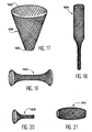
- FIG. 15 represents a wire 140 in shape memory material of which only a part end 142 is annealed by a process in accordance with the invention.
- This wire can be used as a guide wire in minimally invasive surgery to guide a catheter. Only the end is superelastic, which allows ability to follow curves of arteries and veins in human body without damaging tissue. Part 144 rigid, meanwhile, ensures good torsional rigidity, thus avoiding the effect of "blow of whip ".
- part 142 The superelasticity of part 142 is mechanically induced.
- Figure 16 shows an example of pliers with biopsy 148 usable in minimally invasive surgery to take tissue samples from the body human.
- This clip in shape memory material forms a lasso of which only the loop 150 is annealed by a method according to the invention.
- This loop 150 can be closed for example by a weld 152.
- the non-annealed part 154 more rigid, allows to have a good torsional and bending stiffness.
- the superelasticity of the loop 150 is mechanically induced: initially the clamp is in a catheter 156. We then push out of this catheter the end corresponding to the loop (to the right in Figure 15) and this end takes this form because of its superelasticity.
- Figure 17 shows an example endocalibrator or stent 158 made of memory material form.
- Local annealing by a process in accordance with the invention allows in the case of endocalibreurs or stents, to create more or less rigid zones regardless of the type of mesh. So the areas not annealed will not have the same expansion at exit of the catheter as the annealed areas.
- a cone-shaped stent can be achieved by performing progressive annealing on the mesh of the stent.
- the end 160 of the stent is non-annealed. The rest of the stent is gradually annealed, i.e.
- Figures 18 to 21 show other examples of stents made of shape memory material, obeying the same principle as that of figure 17.
- it is a stent 164 able to take an elongated shape with two diameters.
- Other envelope geometries are possible for a stent: in the case of figure 19 the stent 166 takes a shape has two ends of larger diameter than the rest of the stent.
- the stent 168 takes on a flared shape.
- the stent 170 takes a swollen shape in its center.
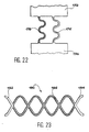
- Figure 22 is a schematic view of a shock absorber system in shape memory material and comprising two parts 172 and 174 connected by two elements 176 and 178 wavy and substantially parallel.
- Element 176 is not annealed while element 178 is annealed by a process according to the invention.
- shape memory alloys have the property of having a very high depreciation rate in martensite (this being due to internal friction in matter).
- With local annealing a spring with integrated shock absorber. So the element not annealed 176 behaves like a normal spring while that the annealed element 178 is capable of playing the role damper.
- Figure 23 is a schematic view of a 180 unfolded monolithic watch strap made of material with shape memory. Only the end parts 182 and 184 of the bracelet, to be fixed to the case of the watch (not shown) are not annealed. central 186 of the bracelet, part between parts 182 and 184 is therefore annealed by a process according to the invention and its annealing can be progressive according to the desired rigidity. Various decorative elements (not shown), for example ceramic plates, can be added to the structure thus obtained. Such a bracelet can be made tailored.
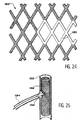
- Figure 24 is a schematic view and partial of a stent 188 in memory material of form.
- the entire mesh of the stent is annealed by a method according to the invention, except a number limited N of meshes with 1 ⁇ N ⁇ 10 (zone referenced 190 in Figure 24).
- FIG 25 schematically illustrates a application of the stent of figure 24.
- This stent 188 is placed in a artery 192.
- the non-annealed meshes are plastically deformed using a balloon 196 brought into contact with these meshes in going through artery 194 and the kind of those that are used to deploy steel stents. These meshes thus distorted allow the restoration of the blood circulation in the artery 194.
- the balloon can also be introduced via artery 192 in passing inside the stent itself and then fork at artery level 194.
Landscapes
- Chemical & Material Sciences (AREA)
- Mechanical Engineering (AREA)
- Organic Chemistry (AREA)
- Crystallography & Structural Chemistry (AREA)
- Engineering & Computer Science (AREA)
- Materials Engineering (AREA)
- Physics & Mathematics (AREA)
- Metallurgy (AREA)
- Thermal Sciences (AREA)
- Heat Treatment Of Articles (AREA)
- Micromachines (AREA)
- Encapsulation Of And Coatings For Semiconductor Or Solid State Devices (AREA)
- Laser Beam Processing (AREA)
- Manufacturing Of Printed Circuit Boards (AREA)
- Surgical Instruments (AREA)
Description
- la cristallisation locale de l'objet lorsque le matériau est amorphe
- ou la recristallisation locale de l'objet lorsque le matériau est écroui
- ou la cristallisation secondaire locale de l'objet lorsque le matériau est déjà cristallisé (par exemple pour induire localement un changement de température de transformation)
- ou la formation contrôlée de précipités ou encore l'annihilation de défauts cristallins, localement, dans l'objet (en vue de changer localement les propriétés mécaniques de celui-ci).
- Ce procédé peut être mis en oeuvre avec un dispositif peu coûteux et permet de réaliser des recuits de structures en matériaux à mémoire de forme de façon simple, sans avoir recours à un four (la durée du traitement selon l'invention étant beaucoup plus courte que celle d'un recuit effectué au moyen d'un four). De plus, un tel procédé est facilement implantable dans une chaíne de production.
- Ce procédé permet de recuire de petites zones prédéfinies dans des structures complexes, de façon très précise.
- Ce procédé est compatible avec une grande liberté de conception des structures avec lesquelles on veut le mettre en oeuvre (alors qu'un recuit local au moyen d'un courant électrique nécessiterait un chemin de courant bien défini et dimensionné).
- Avec ce procédé, l'élévation de température se fait très rapidement et le refroidissement ne dépend que de la taille de l'objet à recuire. Ceci permet d'obtenir des qualités de recuit qui sont difficiles à obtenir avec un four. A titre d'exemple, une trempe en fin de recuit n'est plus nécessaire avec l'invention.
- Ce procédé est très bien adapté à la production de systèmes micro-électro-mécaniques (« micro-electro-mechanical systems ») ou MEMS, peut être intégré dans un procédé de fabrication de micro-systèmes et permet une production rapide de ces derniers.
- Ce procédé est le seul qui permette de réaliser des actionneurs réversibles, de très petites dimensions, sans avoir recours à une mise sous contrainte par une pré-déformation mécanique effectuée par un opérateur. L'invention permet d'introduire cette pré-déformation lors du recuit.
- Les applications de l'invention sont nombreuses et se situent notamment dans les microtechniques (MEMS) : elle permet par exemple de fabriquer des micro-commutateurs pour fibres optiques, des modulateurs, des préhenseurs, des fixations actives, des axes de translation et des axes de rotations, monolithiques.
- la figure 1 est une vue schématique d'un dispositif permettant de mettre en oeuvre le procédé objet de l'invention,
- la figure 2 est une vue schématique d'un objet dont la partie non recuite n'est pas d'un seul tenant,
- la figure 3 est une vue schématique d'un objet dont la partie non recuite est d'un seul tenant,
- la figure 4 est une vue schématique d'une lame rigidifiée par un procédé conforme à l'invention,
- la figure 5 est une vue schématique d'un étage de translation suivant un axe, dont la fabrication utilise le procédé objet de l'invention,
- la figure 6 est une vue schématique d'un préhenseur dont la fabrication utilise le procédé objet de l'invention,
- la figure 7 est une vue schématique d'un commutateur optique dont la fabrication utilise le procédé objet de l'invention,
- la figure 8 est une vue schématique d'un actionneur dont la fabrication utilise le procédé objet de l'invention,
- la figure 9A est une vue de dessus schématique d'un autre actionneur dont la fabrication utilise un recuit conformément au procédé objet de l'invention tandis que la figure 9B est une vue de profil de cet autre actionneur après ce recuit,
- la figure 10 est une vue schématique d'une table de translation qui est munie d'éléments de guidage, avec des articulations, et dont la fabrication utilise le procédé objet de l'invention, et
- les figures 11 à 25 illustrent schématiquement d'autres applications de procédé objet de la présente invention.
AgCd, AuCd, CuZn, CuZnX (où X=Si, Sn, Al ou Ga), CuAlNi, CuSn, CuAuZn, NiAl, TiNi, TiNiX (où X=HF, Cu, Nb, Pd, Co), TiPdNi, InTl, InCd et MnCd.
Claims (7)
- Procédé de traitement d'un objet (2, 20) en un matériau apte à présenter un effet de mémoire de forme et étant à l'état amorphe ou écroui avant traitement, l'objet n'ayant à ce stade pas d'effet mémoire, ce procédé étant caractérisé en ce qu'on irradie une partie de cet objet dans une ou plusieurs zones prédéfinies (A; 36; 52; 68; 76, 80; 90) par un faisceau laser (4) apte à chauffer suffisamment cette zone, à une température inférieure à la température de fusion du matériau, pour provoquer dans ladite zone, un changement de la microstructure choisi parmi une cristallisation, une recristallisation, une cristallisation secondaire, une formation contrôlée de précipités et une annihilation de défauts cristallins, ladite zone étant chauffée à une température et pendant un temps aptes à ne pas provoquer une amorphisation du matériau et de telle manière à obtenir un effet de mémoire de forme dans ladite zone chauffée.
- Procédé selon la revendication 1, dans lequel on utilise en outre ladite irradiation de la zone (68, 76, 90) pour provoquer une déformation permanente de cette zone permettant une mise sous contrainte de l'objet.
- Procédé selon la revendication 1, dans lequel, avant et pendant, ou après, l'irradiation de la zone (36, 52), l'objet est mis sous contrainte par déformation dudit objet.
- Procédé selon l'une quelconque des revendications 1 à 3, dans lequel la partie non irradiée (30) de l'objet (20) est d'un seul tenant.
- Procédé selon l'une quelconque des revendications 1 à 3, dans lequel la partie non irradiée de l'objet (20) comprend au moins deux zones (24, 26) qui sont séparées par la zone irradiée (22).
- Procédé selon la revendication 1, dans lequel l'objet est un élément mince (20) et l'on irradie, au moyen dudit faisceau laser, des zones (32) de cet élément qui sont réparties sur ledit élément en vue de rigidifier ce dernier.
- Procédé selon l'une quelconque des revendications 1 à 6, dans lequel on fait varier l'énergie transmise au matériau par le laser en fonction de la position du faisceau laser sur l'objet.
Applications Claiming Priority (3)
| Application Number | Priority Date | Filing Date | Title |
|---|---|---|---|
| FR9815376 | 1998-12-04 | ||
| FR9815376A FR2786790B1 (fr) | 1998-12-04 | 1998-12-04 | Procede de traitement par laser d'un objet en materiau a memoire de forme |
| PCT/EP1999/009714 WO2000034536A1 (fr) | 1998-12-04 | 1999-12-03 | Procede de traitement par laser d'un objet |
Publications (2)
| Publication Number | Publication Date |
|---|---|
| EP1141423A1 EP1141423A1 (fr) | 2001-10-10 |
| EP1141423B1 true EP1141423B1 (fr) | 2004-10-13 |
Family
ID=9533627
Family Applications (1)
| Application Number | Title | Priority Date | Filing Date |
|---|---|---|---|
| EP99967929A Expired - Lifetime EP1141423B1 (fr) | 1998-12-04 | 1999-12-03 | Procede de traitement par laser d'un objet en materiau a memoire de forme |
Country Status (7)
| Country | Link |
|---|---|
| US (1) | US6669794B1 (fr) |
| EP (1) | EP1141423B1 (fr) |
| JP (1) | JP2002531707A (fr) |
| AT (1) | ATE279539T1 (fr) |
| DE (1) | DE69921185T2 (fr) |
| FR (1) | FR2786790B1 (fr) |
| WO (1) | WO2000034536A1 (fr) |
Families Citing this family (34)
| Publication number | Priority date | Publication date | Assignee | Title |
|---|---|---|---|---|
| US6771895B2 (en) | 1999-01-06 | 2004-08-03 | Mattson Technology, Inc. | Heating device for heating semiconductor wafers in thermal processing chambers |
| DE19952295A1 (de) * | 1999-10-29 | 2001-05-23 | Angiomed Ag | Verfahren zur Herstellung eines Stents |
| US6588208B1 (en) * | 2001-01-29 | 2003-07-08 | Technology Innovations, Llc | Wireless technique for microactivation |
| GB2373464B (en) * | 2001-03-22 | 2004-04-07 | Revel Internat Ltd | Components for spectacles and methods of making such components |
| US20030101225A1 (en) * | 2001-11-27 | 2003-05-29 | Song Han | Method and system for providing location-based event service |
| US20050091975A1 (en) * | 2002-01-28 | 2005-05-05 | Technology Innovations, Llc | Microactivation using fiber optic and wireless means |
| US7455737B2 (en) * | 2003-08-25 | 2008-11-25 | Boston Scientific Scimed, Inc. | Selective treatment of linear elastic materials to produce localized areas of superelasticity |
| US7586828B1 (en) | 2003-10-23 | 2009-09-08 | Tini Alloy Company | Magnetic data storage system |
| US20050092403A1 (en) * | 2003-10-29 | 2005-05-05 | Lloyd David J. | Functionally graded aluminum alloy sheet |
| US7632361B2 (en) | 2004-05-06 | 2009-12-15 | Tini Alloy Company | Single crystal shape memory alloy devices and methods |
| US7763342B2 (en) | 2005-03-31 | 2010-07-27 | Tini Alloy Company | Tear-resistant thin film methods of fabrication |
| US7540899B1 (en) * | 2005-05-25 | 2009-06-02 | Tini Alloy Company | Shape memory alloy thin film, method of fabrication, and articles of manufacture |
| US20070246233A1 (en) * | 2006-04-04 | 2007-10-25 | Johnson A D | Thermal actuator for fire protection sprinkler head |
| EP2460544A1 (fr) * | 2006-06-30 | 2012-06-06 | Tyco Healthcare Group LP | Dispositifs médicaux avec des métaux amorphes et procédés correspondants |
| DE102006050799A1 (de) * | 2006-10-27 | 2008-05-08 | Fraunhofer-Gesellschaft zur Förderung der angewandten Forschung e.V. | Verfahren und Vorrichtung zum Randschichthärten formkomplizierter Bauteile |
| US8349099B1 (en) | 2006-12-01 | 2013-01-08 | Ormco Corporation | Method of alloying reactive components |
| US8684101B2 (en) | 2007-01-25 | 2014-04-01 | Tini Alloy Company | Frangible shape memory alloy fire sprinkler valve actuator |
| US8584767B2 (en) | 2007-01-25 | 2013-11-19 | Tini Alloy Company | Sprinkler valve with active actuation |
| US8007674B2 (en) | 2007-07-30 | 2011-08-30 | Tini Alloy Company | Method and devices for preventing restenosis in cardiovascular stents |
| WO2009073609A1 (fr) | 2007-11-30 | 2009-06-11 | Tini Alloy Company | Alliages cuivreux monocristallins biocompatibles à mémoire de forme |
| US7842143B2 (en) | 2007-12-03 | 2010-11-30 | Tini Alloy Company | Hyperelastic shape setting devices and fabrication methods |
| US8382917B2 (en) | 2007-12-03 | 2013-02-26 | Ormco Corporation | Hyperelastic shape setting devices and fabrication methods |
| US9186853B2 (en) | 2009-08-07 | 2015-11-17 | Smarter Alloys Inc. | Methods and systems for processing materials, including shape memory materials |
| JP5512238B2 (ja) * | 2009-11-13 | 2014-06-04 | 株式会社カネカ | 生体内留置部材の製造方法 |
| US10124197B2 (en) | 2012-08-31 | 2018-11-13 | TiNi Allot Company | Fire sprinkler valve actuator |
| US11040230B2 (en) | 2012-08-31 | 2021-06-22 | Tini Alloy Company | Fire sprinkler valve actuator |
| DE102013008396B4 (de) * | 2013-05-17 | 2015-04-02 | G. Rau Gmbh & Co. Kg | Verfahren und Vorrichtung zum Umschmelzen und/oder Umschmelzlegieren metallischer Werkstoffe, insbesondere von Nitinol |
| JP2015036455A (ja) * | 2013-08-12 | 2015-02-23 | クリノ株式会社 | 医療用Ti−Ni合金 |
| ES2683219T3 (es) | 2013-09-06 | 2018-09-25 | Ormco Corporation | Aparatos ortodóncicos y métodos de hacerlos |
| CA2955075A1 (fr) * | 2014-07-14 | 2016-01-21 | Smarter Alloys Inc. | Materiaux a memoires multiples et systemes, procedes et applications associes |
| JP6738159B2 (ja) * | 2016-02-29 | 2020-08-12 | 株式会社パイオラックスメディカルデバイス | ガイドワイヤ |
| RU2692711C1 (ru) * | 2016-04-21 | 2019-06-26 | федеральное государственное автономное образовательное учреждение высшего профессионального образования "Национальный исследовательский ядерный университет МИФИ" (НИЯУ МИФИ) | СПОСОБ ИЗГОТОВЛЕНИЯ ФУНКЦИОНАЛЬНОГО МАТЕРИАЛА С ОБРАТИМОЙ ПАМЯТЬЮ ФОРМЫ ИЗ КВАЗИБИНАРНОГО СПЛАВА ИНТЕРМЕТАЛЛИЧЕСКОЙ СИСТЕМЫ TiNi-TiCu (ВАРИАНТЫ) |
| RU2677033C1 (ru) * | 2017-12-27 | 2019-01-15 | Станислав Викторович Евсеев | Способ обработки поверхности сплава никелида титана |
| EP3922294B1 (fr) * | 2019-02-06 | 2026-03-11 | Asahi Intecc Co., Ltd. | Fil-guide |
Family Cites Families (15)
| Publication number | Priority date | Publication date | Assignee | Title |
|---|---|---|---|---|
| GB1373490A (en) * | 1970-12-09 | 1974-11-13 | British Steel Corp | Heat treatment of metal strip |
| US4151014A (en) * | 1977-05-31 | 1979-04-24 | Western Electric Company, Inc. | Laser annealing |
| FR2475270A1 (fr) * | 1980-02-01 | 1981-08-07 | Thomson Csf | Structure de memoire reversible, a inscription thermo-optique et lecture optique, et procede d'inscription et d'effacement de cette structure |
| IT1155601B (it) * | 1982-02-12 | 1987-01-28 | Fiat Ricerche | Metodo per realizzare un basamento di un motore endotermico alternativo e basamento realizzato con tale procedimento |
| US4777799A (en) * | 1987-10-02 | 1988-10-18 | Catheter Research, Inc. | Memory element |
| US4881981A (en) * | 1988-04-20 | 1989-11-21 | Johnson Service Company | Method for producing a shape memory alloy member having specific physical and mechanical properties |
| EP0360455A3 (fr) * | 1988-09-19 | 1992-08-05 | Catheter Research, Inc. | Elément de mémoire fractionnel |
| GB2257163B (en) * | 1991-07-02 | 1995-04-05 | Res & Dev Min Def Gov In | A process for improving fatigue crack growth resistance |
| US5514115A (en) * | 1993-07-07 | 1996-05-07 | Device For Vascular Intervention, Inc. | Flexible housing for intracorporeal use |
| US5728240A (en) * | 1994-12-16 | 1998-03-17 | Sharp Kabushiki Kaisha | Positionally adjustable member and applications therefor |
| BE1009480A3 (nl) * | 1995-07-11 | 1997-04-01 | Advanced Materials Tech | Werkwijze voor het aan elkaar bevestigen van twee elementen, in het bijzonder schakels van een metalen polshorlogeband. |
| US5617377A (en) * | 1995-12-13 | 1997-04-01 | Perret, Jr.; Gerard A. | Watchband connector pin utilizing shape memory material |
| JP3691579B2 (ja) * | 1996-04-26 | 2005-09-07 | 古河電気工業株式会社 | 形状記憶合金部材及びその製造方法 |
| FR2756767A1 (fr) * | 1996-12-06 | 1998-06-12 | Andromis Sa | Dispositif de prehension en materiau a memoire de forme et procede de realisation |
| AU746009B2 (en) * | 1997-01-24 | 2002-04-11 | Celonova Stent, Inc | Bistable spring construction for a stent and other medical apparatus |
-
1998
- 1998-12-04 FR FR9815376A patent/FR2786790B1/fr not_active Expired - Fee Related
-
1999
- 1999-12-03 JP JP2000586968A patent/JP2002531707A/ja active Pending
- 1999-12-03 EP EP99967929A patent/EP1141423B1/fr not_active Expired - Lifetime
- 1999-12-03 WO PCT/EP1999/009714 patent/WO2000034536A1/fr not_active Ceased
- 1999-12-03 AT AT99967929T patent/ATE279539T1/de not_active IP Right Cessation
- 1999-12-03 US US09/857,437 patent/US6669794B1/en not_active Expired - Fee Related
- 1999-12-03 DE DE69921185T patent/DE69921185T2/de not_active Expired - Lifetime
Also Published As
| Publication number | Publication date |
|---|---|
| US6669794B1 (en) | 2003-12-30 |
| DE69921185T2 (de) | 2006-02-02 |
| EP1141423A1 (fr) | 2001-10-10 |
| JP2002531707A (ja) | 2002-09-24 |
| ATE279539T1 (de) | 2004-10-15 |
| DE69921185D1 (de) | 2004-11-18 |
| FR2786790B1 (fr) | 2001-02-23 |
| WO2000034536A1 (fr) | 2000-06-15 |
| FR2786790A1 (fr) | 2000-06-09 |
Similar Documents
| Publication | Publication Date | Title |
|---|---|---|
| EP1141423B1 (fr) | Procede de traitement par laser d'un objet en materiau a memoire de forme | |
| EP0807276B1 (fr) | Monture de lunettes metallique | |
| US8382917B2 (en) | Hyperelastic shape setting devices and fabrication methods | |
| EP1060280B1 (fr) | Procede ameliorant la ductilite du nitinol | |
| EP2510405B1 (fr) | Procede de fabrication d'un ressort pour piece d'horlogerie | |
| JP2018053362A (ja) | モノリスニチノール合金 | |
| EP1730604B1 (fr) | Dispositif et procede de fixation d'une levee sur une ancre d'un echappement d'un mouvement d'horlogerie | |
| EP0864664A1 (fr) | Procédé de fabrication d'une pièce superélastique en alliage de nickel et de titane | |
| US7842143B2 (en) | Hyperelastic shape setting devices and fabrication methods | |
| EP2596140A1 (fr) | Composant horloger comprenant un alliage métallique amorphe | |
| EP2400354A1 (fr) | Pieds de cadran de pièce d'horlogerie | |
| CA2542078A1 (fr) | Nitinol a longevite a la fatigue elevee | |
| Nakata et al. | Lines of periodic hole structures produced by laser ablation using interfering femtosecond lasers split by a transmission grating | |
| EP0946334A2 (fr) | Dispositif de prehension en materiau a memoire de forme et procede de realisation | |
| WO2011161138A1 (fr) | Procede de reglage de la position relative d'une premiere et d'une seconde pieces d'un ensemble mecanique | |
| Ikuta et al. | Shape memory alloy thin film fabricated by laser ablation | |
| US7441888B1 (en) | Eyeglass frame | |
| Biffi et al. | Laser-induced superelasticity in NiTinol stent strut | |
| EP0382109B1 (fr) | Procédé de conditionnement d'une pièce en alliage métallique à mémoire de forme présentant deux états de mémoire de forme réversibles | |
| JP2008156706A (ja) | 形状記憶部材の製造方法 | |
| EP0983529B1 (fr) | Monture de lunettes a elements en alliage superelastique | |
| Khan | Pulsed Nd: YAG laser processing of nitinol | |
| FR2643086A1 (fr) | Procede de conditionnement d'une piece en alliage metallique a memoire de forme presentant deux etats de memoire de forme reversibles | |
| Haferkamp et al. | New laser machining processes for shape memory alloys | |
| Muniraj et al. | Laser induced forward transfer of NiTi deposits for functionally graded SMA components |
Legal Events
| Date | Code | Title | Description |
|---|---|---|---|
| PUAI | Public reference made under article 153(3) epc to a published international application that has entered the european phase |
Free format text: ORIGINAL CODE: 0009012 |
|
| 17P | Request for examination filed |
Effective date: 20010704 |
|
| AK | Designated contracting states |
Kind code of ref document: A1 Designated state(s): AT BE CH CY DE DK ES FI FR GB GR IE IT LI LU MC NL PT SE |
|
| 17Q | First examination report despatched |
Effective date: 20020116 |
|
| GRAH | Despatch of communication of intention to grant a patent |
Free format text: ORIGINAL CODE: EPIDOS IGRA |
|
| RTI1 | Title (correction) |
Free format text: METHOD FOR TREATING WITH LASER AN OBJET CONSISTING OF A SHAPE MEMORY MATERIAL |
|
| GRAS | Grant fee paid |
Free format text: ORIGINAL CODE: EPIDOSNIGR3 |
|
| RAP1 | Party data changed (applicant data changed or rights of an application transferred) |
Owner name: ETA SA MANUFACTURE HORLOGERE SUISSE |
|
| GRAA | (expected) grant |
Free format text: ORIGINAL CODE: 0009210 |
|
| AK | Designated contracting states |
Kind code of ref document: B1 Designated state(s): AT BE CH CY DE DK ES FI FR GB GR IE IT LI LU MC NL PT SE |
|
| PG25 | Lapsed in a contracting state [announced via postgrant information from national office to epo] |
Ref country code: SE Free format text: LAPSE BECAUSE OF FAILURE TO SUBMIT A TRANSLATION OF THE DESCRIPTION OR TO PAY THE FEE WITHIN THE PRESCRIBED TIME-LIMIT Effective date: 20041013 Ref country code: NL Free format text: LAPSE BECAUSE OF FAILURE TO SUBMIT A TRANSLATION OF THE DESCRIPTION OR TO PAY THE FEE WITHIN THE PRESCRIBED TIME-LIMIT Effective date: 20041013 Ref country code: IT Free format text: LAPSE BECAUSE OF FAILURE TO SUBMIT A TRANSLATION OF THE DESCRIPTION OR TO PAY THE FEE WITHIN THE PRESCRIBED TIME-LIMIT;WARNING: LAPSES OF ITALIAN PATENTS WITH EFFECTIVE DATE BEFORE 2007 MAY HAVE OCCURRED AT ANY TIME BEFORE 2007. THE CORRECT EFFECTIVE DATE MAY BE DIFFERENT FROM THE ONE RECORDED. Effective date: 20041013 Ref country code: IE Free format text: LAPSE BECAUSE OF FAILURE TO SUBMIT A TRANSLATION OF THE DESCRIPTION OR TO PAY THE FEE WITHIN THE PRESCRIBED TIME-LIMIT Effective date: 20041013 Ref country code: FI Free format text: LAPSE BECAUSE OF FAILURE TO SUBMIT A TRANSLATION OF THE DESCRIPTION OR TO PAY THE FEE WITHIN THE PRESCRIBED TIME-LIMIT Effective date: 20041013 Ref country code: CY Free format text: LAPSE BECAUSE OF FAILURE TO SUBMIT A TRANSLATION OF THE DESCRIPTION OR TO PAY THE FEE WITHIN THE PRESCRIBED TIME-LIMIT Effective date: 20041013 Ref country code: AT Free format text: LAPSE BECAUSE OF FAILURE TO SUBMIT A TRANSLATION OF THE DESCRIPTION OR TO PAY THE FEE WITHIN THE PRESCRIBED TIME-LIMIT Effective date: 20041013 |
|
| REG | Reference to a national code |
Ref country code: GB Ref legal event code: FG4D Free format text: NOT ENGLISH |
|
| REG | Reference to a national code |
Ref country code: CH Ref legal event code: EP |
|
| REG | Reference to a national code |
Ref country code: IE Ref legal event code: FG4D Free format text: FRENCH |
|
| REF | Corresponds to: |
Ref document number: 69921185 Country of ref document: DE Date of ref document: 20041118 Kind code of ref document: P |
|
| PG25 | Lapsed in a contracting state [announced via postgrant information from national office to epo] |
Ref country code: LU Free format text: LAPSE BECAUSE OF NON-PAYMENT OF DUE FEES Effective date: 20041203 |
|
| PG25 | Lapsed in a contracting state [announced via postgrant information from national office to epo] |
Ref country code: MC Free format text: LAPSE BECAUSE OF NON-PAYMENT OF DUE FEES Effective date: 20041231 Ref country code: BE Free format text: LAPSE BECAUSE OF NON-PAYMENT OF DUE FEES Effective date: 20041231 |
|
| PG25 | Lapsed in a contracting state [announced via postgrant information from national office to epo] |
Ref country code: GR Free format text: LAPSE BECAUSE OF FAILURE TO SUBMIT A TRANSLATION OF THE DESCRIPTION OR TO PAY THE FEE WITHIN THE PRESCRIBED TIME-LIMIT Effective date: 20050113 Ref country code: DK Free format text: LAPSE BECAUSE OF FAILURE TO SUBMIT A TRANSLATION OF THE DESCRIPTION OR TO PAY THE FEE WITHIN THE PRESCRIBED TIME-LIMIT Effective date: 20050113 |
|
| PG25 | Lapsed in a contracting state [announced via postgrant information from national office to epo] |
Ref country code: ES Free format text: LAPSE BECAUSE OF FAILURE TO SUBMIT A TRANSLATION OF THE DESCRIPTION OR TO PAY THE FEE WITHIN THE PRESCRIBED TIME-LIMIT Effective date: 20050124 |
|
| REG | Reference to a national code |
Ref country code: CH Ref legal event code: NV Representative=s name: ICB INGENIEURS CONSEILS EN BREVETS SA |
|
| GBT | Gb: translation of ep patent filed (gb section 77(6)(a)/1977) |
Effective date: 20050201 |
|
| NLV1 | Nl: lapsed or annulled due to failure to fulfill the requirements of art. 29p and 29m of the patents act | ||
| REG | Reference to a national code |
Ref country code: IE Ref legal event code: FD4D |
|
| BERE | Be: lapsed |
Owner name: ETA SA MANUFACTURE HORLOGERE SUISSE Effective date: 20041231 |
|
| PLBE | No opposition filed within time limit |
Free format text: ORIGINAL CODE: 0009261 |
|
| STAA | Information on the status of an ep patent application or granted ep patent |
Free format text: STATUS: NO OPPOSITION FILED WITHIN TIME LIMIT |
|
| 26N | No opposition filed |
Effective date: 20050714 |
|
| BERE | Be: lapsed |
Owner name: S.A. *ETA MANUFACTURE HORLOGERE SUISSE Effective date: 20041231 |
|
| PG25 | Lapsed in a contracting state [announced via postgrant information from national office to epo] |
Ref country code: PT Free format text: LAPSE BECAUSE OF NON-PAYMENT OF DUE FEES Effective date: 20050313 |
|
| PGFP | Annual fee paid to national office [announced via postgrant information from national office to epo] |
Ref country code: GB Payment date: 20091125 Year of fee payment: 11 |
|
| GBPC | Gb: european patent ceased through non-payment of renewal fee |
Effective date: 20101203 |
|
| PG25 | Lapsed in a contracting state [announced via postgrant information from national office to epo] |
Ref country code: GB Free format text: LAPSE BECAUSE OF NON-PAYMENT OF DUE FEES Effective date: 20101203 |
|
| PGFP | Annual fee paid to national office [announced via postgrant information from national office to epo] |
Ref country code: CH Payment date: 20141126 Year of fee payment: 16 Ref country code: DE Payment date: 20141121 Year of fee payment: 16 |
|
| PGFP | Annual fee paid to national office [announced via postgrant information from national office to epo] |
Ref country code: FR Payment date: 20141217 Year of fee payment: 16 |
|
| REG | Reference to a national code |
Ref country code: DE Ref legal event code: R119 Ref document number: 69921185 Country of ref document: DE |
|
| REG | Reference to a national code |
Ref country code: CH Ref legal event code: PL |
|
| REG | Reference to a national code |
Ref country code: FR Ref legal event code: ST Effective date: 20160831 |
|
| PG25 | Lapsed in a contracting state [announced via postgrant information from national office to epo] |
Ref country code: CH Free format text: LAPSE BECAUSE OF NON-PAYMENT OF DUE FEES Effective date: 20151231 Ref country code: LI Free format text: LAPSE BECAUSE OF NON-PAYMENT OF DUE FEES Effective date: 20151231 Ref country code: DE Free format text: LAPSE BECAUSE OF NON-PAYMENT OF DUE FEES Effective date: 20160701 |
|
| PG25 | Lapsed in a contracting state [announced via postgrant information from national office to epo] |
Ref country code: FR Free format text: LAPSE BECAUSE OF NON-PAYMENT OF DUE FEES Effective date: 20151231 |