EP1141987B1 - Schutzschalter zur absicherung von stromkreisen in strassenfahrzeugen - Google Patents
Schutzschalter zur absicherung von stromkreisen in strassenfahrzeugen Download PDFInfo
- Publication number
- EP1141987B1 EP1141987B1 EP99968780A EP99968780A EP1141987B1 EP 1141987 B1 EP1141987 B1 EP 1141987B1 EP 99968780 A EP99968780 A EP 99968780A EP 99968780 A EP99968780 A EP 99968780A EP 1141987 B1 EP1141987 B1 EP 1141987B1
- Authority
- EP
- European Patent Office
- Prior art keywords
- circuit breaker
- housing
- manual release
- contact
- breaker according
- Prior art date
- Legal status (The legal status is an assumption and is not a legal conclusion. Google has not performed a legal analysis and makes no representation as to the accuracy of the status listed.)
- Expired - Lifetime
Links
- 239000011810 insulating material Substances 0.000 claims abstract description 5
- 239000003086 colorant Substances 0.000 claims description 2
- 238000003780 insertion Methods 0.000 claims description 2
- 230000037431 insertion Effects 0.000 claims description 2
- 238000000034 method Methods 0.000 claims 1
- 230000006835 compression Effects 0.000 description 9
- 238000007906 compression Methods 0.000 description 9
- 238000010276 construction Methods 0.000 description 4
- 241001417534 Lutjanidae Species 0.000 description 2
- 230000013011 mating Effects 0.000 description 2
- 238000006073 displacement reaction Methods 0.000 description 1
- 230000000694 effects Effects 0.000 description 1
- 238000005516 engineering process Methods 0.000 description 1
- 238000013100 final test Methods 0.000 description 1
- 238000010438 heat treatment Methods 0.000 description 1
- 230000007774 longterm Effects 0.000 description 1
- 230000004048 modification Effects 0.000 description 1
- 238000012986 modification Methods 0.000 description 1
- 238000000926 separation method Methods 0.000 description 1
- 230000011664 signaling Effects 0.000 description 1
- 239000013589 supplement Substances 0.000 description 1
- 230000001960 triggered effect Effects 0.000 description 1
Images

Classifications
-
- H—ELECTRICITY
- H01—ELECTRIC ELEMENTS
- H01H—ELECTRIC SWITCHES; RELAYS; SELECTORS; EMERGENCY PROTECTIVE DEVICES
- H01H73/00—Protective overload circuit-breaking switches in which excess current opens the contacts by automatic release of mechanical energy stored by previous operation of a hand reset mechanism
- H01H73/22—Protective overload circuit-breaking switches in which excess current opens the contacts by automatic release of mechanical energy stored by previous operation of a hand reset mechanism having electrothermal release and no other automatic release
-
- H—ELECTRICITY
- H01—ELECTRIC ELEMENTS
- H01H—ELECTRIC SWITCHES; RELAYS; SELECTORS; EMERGENCY PROTECTIVE DEVICES
- H01H9/00—Details of switching devices, not covered by groups H01H1/00 - H01H7/00
- H01H9/30—Means for extinguishing or preventing arc between current-carrying parts
- H01H9/32—Insulating body insertable between contacts
-
- H—ELECTRICITY
- H01—ELECTRIC ELEMENTS
- H01H—ELECTRIC SWITCHES; RELAYS; SELECTORS; EMERGENCY PROTECTIVE DEVICES
- H01H73/00—Protective overload circuit-breaking switches in which excess current opens the contacts by automatic release of mechanical energy stored by previous operation of a hand reset mechanism
- H01H73/22—Protective overload circuit-breaking switches in which excess current opens the contacts by automatic release of mechanical energy stored by previous operation of a hand reset mechanism having electrothermal release and no other automatic release
- H01H73/30—Protective overload circuit-breaking switches in which excess current opens the contacts by automatic release of mechanical energy stored by previous operation of a hand reset mechanism having electrothermal release and no other automatic release reset by push-button, pull-knob or slide
- H01H73/303—Protective overload circuit-breaking switches in which excess current opens the contacts by automatic release of mechanical energy stored by previous operation of a hand reset mechanism having electrothermal release and no other automatic release reset by push-button, pull-knob or slide with an insulating body insertable between the contacts when released by a bimetal element
-
- H—ELECTRICITY
- H01—ELECTRIC ELEMENTS
- H01H—ELECTRIC SWITCHES; RELAYS; SELECTORS; EMERGENCY PROTECTIVE DEVICES
- H01H71/00—Details of the protective switches or relays covered by groups H01H73/00 - H01H83/00
- H01H71/08—Terminals; Connections
- H01H2071/088—Terminals for switching devices which make the devices interchangeable, e.g. with fuses
-
- H—ELECTRICITY
- H01—ELECTRIC ELEMENTS
- H01H—ELECTRIC SWITCHES; RELAYS; SELECTORS; EMERGENCY PROTECTIVE DEVICES
- H01H71/00—Details of the protective switches or relays covered by groups H01H73/00 - H01H83/00
- H01H71/10—Operating or release mechanisms
- H01H71/12—Automatic release mechanisms with or without manual release
- H01H71/128—Manual release or trip mechanisms, e.g. for test purposes
Definitions
- the invention relates to a circuit breaker for protecting circuits in road vehicles with the features listed in the preamble of claim 1 (EP 0 151 692 B1; DE 35 26 785 C1).
- Such circuit breakers are intended to replace conventional ones Fuses according to DIN 72581-3 in worldwide with flat fuse bases equipped motor vehicles are used.
- the invention is based, with a circuit breaker of the aforementioned object Kind in a simpler manner, a principle already known from DE-A-1099624 Possibility to create the circuit protected by the auto switch can also be interrupted arbitrarily without overcurrent tripping.
- a principle already known from DE-A-1099624 Possibility to create the circuit protected by the auto switch can also be interrupted arbitrarily without overcurrent tripping.
- Protection of the electrical circuits of motor vehicles is a requirement if e.g. with a longer one
- the battery is drained by leakage currents should be effectively prevented. That is, for example, after a final test of the Vehicle until delivery to the customer. In between often long-term transport or storage times. This object is achieved by claim 1 solved.
- the solution is particularly due to the miniaturized dimensions of the Circuit breaker matched predetermined conditions.
- the hand release designed as a two-armed swivel lever the trigger arm in the rest position is positioned on the contact side of the bimetal spring washer. In contact position the bimetal spring washer, the trigger arm does not touch the bimetal. Rather, it is held without contact in this starting and rest position. That will be through one Spring pressure causes that of the bearing axis of the hand release on its lower Leg is exercised as a swivel drive.
- a circuit breaker of the type according to the invention is a mass article.
- the hand release is light and safe, even in the notoriously cramped Ambient conditions of many circuit breakers arranged side by side operable. Whether his triggering movement caused the desired contact separation is in the embodiment with an additional slide valve according to claim 2 unmistakably recognizable by the fact that after a manual release the Isolating slide with its pressure end protruding from the switch housing.
- the from Actuating arm of the hand release protruding from the housing prevents traceability of the slide valve by pressurizing its print end just as little like the automatic snap-in contact that is then possible when the bimetal has cooled or reclosing the circuit breaker. Therefore, the subject of the invention simply with the construction of the above mentioned remaining unchanged Realize the state of the art.
- the base part made of insulating material is 1 sprayed around the two parallel flat tabs 2, 3. Thereby the housing-fixed fixation of the tabs 2.3 is accomplished.
- the flat plug 2,3 stand with their plug ends outwards from the base part 1. Your Ends 4,5 inside the housing are in the interior of the circuit breaker into it.
- the tabs 3, 4 run correspondingly over their entire longitudinal extent the specification of DIN standard 72581-3 regarding known fuses effective flat fuse links.
- the tabs 3, 4 run essentially parallel to the housing cover surfaces 6, 7 on the base part 1 in the longitudinal direction 9 slide-on housing cap 8. In the slide-on or mounting position Housing cap 8 snap-fitted to the base part 1.
- the fixing opening 10 snaps in of the housing cover surface 6 on the fixing tooth 11 of the base part 1.
- the tabs 2,3 have the cross-sectional shape of a flat over their entire length Rectangle.
- the bimetallic snap disk 12 fixed with its fixing end 13 to the fixing point 14, e.g. welded.
- the bimetallic snap disk 12 protrudes with its end of movement 15 as Contact end in an overlap position with the inner end 5 of the other Flat connector 3 off.
- This inner end 5 carries on its top the stationary Mating contact 16 for that on the underside of the movement end 15 of the bimetal spring washer 12 fixed movement contact 17.
- FIGS. 2 and 5 The current path between the two tabs 2 and 3 is thus closed.
- This The closed position is shown in FIGS. 2 and 5.
- In this closed position there is a Isolating slide 18 on the flank of the movement contact facing the base part 1 17 on. It is opposed by the tensioned compression spring 19 in the longitudinal direction 9 Pressure direction pushed against this edge of the movement contact 17.
- the Compression spring 19 is supported with its rear end 20 on the base 1.
- the Support surface 21 of the base carries a centering pin 22 for securing the position as Coil spring trained compression spring 20 within the switch housing.
- the separating slide 18 forms one leg of a right-angled in plan view (Fig. 1) Formed, the other, protruding against the longitudinal direction 9 leg 23 carries the printing end 24 of the separating slide 18, which is in the contacting position of the contacts 16, 17 (Fig. 2.5) and with a correspondingly compressed compression spring 19 within the housing cap 8 between the inner ends 4, 5 of the flat plugs 2,3 lies and parallel to the inner ends 4,5 positioned on both sides the flat plug 2,3 is aligned.
- the compression spring 19 always exerts still a permanent pressure against the longitudinal direction 9 on the separating slide 18 out.
- Longitudinal displacement of the separating slide 18 is like on a rail on the surface the exposed in the housing inner end 5 of the tab 3.
- a track groove Guide recess 27 (Fig. 1) is provided.
- the printing end 24 is located of the pressure leg 23 of the slide valve 18 through the opening 28 of the housing cap 8 to the outside and thereby signals the completed contact opening.
- This external signaling can be caused by a different color of the housing contrasting signal color of the print end 24 can be ensured or improved.
- the bimetallic spring washer 12 is optionally available from its contacting position (Fig. 2.5) levering hand release 29 available.
- This is a two-armed Lever formed, which facing away from the tabs 2,3 Flat side 30 of the housing cap 8 protrudes with sesinem actuating end.
- the Hand release 29 is next to the leg 23 or the print end 24 of the Isolating slide 18 on the inner end 5 of the tab 3 Positioned side and extends with its longitudinal direction 9 parallel to the leg 23.
- the manual release 29 acts on the contact end 15 of the bimetallic spring washer to open the contact 12 from the contact side carrying the movement contact 17 in the contact opening direction 25.
- This action is effected by the trigger arm 31 of the hand release 29, which is designed as a two-armed swivel lever, for this purpose in the release direction 25 pivoted up around the bearing shaft 32 which is integral with the housing cap 8 becomes.
- the other arm namely the actuating arm, projects outward beyond the bearing axis 32 33 of the manual release 29.
- the actuating arm 33 lies over its entire Length outside the housing cap 8.
- the bearing axis 32 is outside of the housing opening 36 through which the hand release 29 into the housing interior into stands.
- the hand release 29 is a one-piece, approximately U-shaped insulating material part, which includes the bearing axis 32 with its two U-legs.
- the one, namely in the figures lower U-leg is extended by the actuating arm 33 and trigger arm 31 attached to it and protruding into the interior of the housing educated.
- the bearing axis 32 of the manual release 29 is approximately parallel to the bimetal spring washer 12 and aligned with the housing cover surfaces 6.7. It runs vertically to the drawing levels of Fig. 2-7.
- the U-leg of the hand release 29 positioned above the bearing axis 32 is as Fixing leg 37 with one behind the bearing axis 32, in the direction of the Trigger leg 31 projecting retaining lug 38 provided.
- the fixing leg 37 carries on its top a protruding and thereby the insertion length of the manual release 29 with respect to the housing opening 36 limiting housing stop 39, its stop position on the housing top surface 6 can be seen from FIGS. 2.5.
- the lower U-leg namely the trigger arm 31 of the manual trigger 29 is approximately in Middle region of its longitudinal extent to form the bearing shell 41 on its inner flank hollowed out.
- the hand release 29 is by a movable snap connection to the bearing axis 32 snapped on.
- it includes with its two U-legs as an integrated one Snapper and / or as counter surfaces interacting with the snapper Bearing axis 32 resilient.
- the bearing axis has one when the trigger is pivoted 42 of the hand release 29 whose U-leg elastically spreading cross-sectional shape in such a way that the elastic spring pressure stored by the expansion as the manual trigger 29 automatically in its initial pivot position the trigger pivoting 42 returning return pressure is effective.
- This Cross-sectional shape is characterized by a certain asymmetry. This asymmetry is that the U-legs 31,37 in the release pivot position (Fig.
- the U-shape and the resilient consistency of the hand release 29 have in common with the one deviating from a circle and more like an ellipse Cross-sectional shape of the bearing axis 32 a number of advantages. Independent of The cross-sectional shape of the bearing axis 32 is the simple snap assembly of the hand release 29 on the bearing shaft 32 in a captive bracket ensuring it Wise.
- the hand release 29 is simply from the outside in the housing opening 36 inserted U-leg ends pushed on and snapped on.
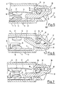
- the postponement or rest position is shown in Figs. 5,7.
- the trigger arm is 31 of the manual release 29 below the bimetal 12.
- the manual release 29 turns clockwise pivoted about the bearing axis 32, the trigger end 31 is raised.
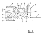
- FIG. 8 shows a modified embodiment of the manual release 29.
- the modification relates to the arrangement of a over the head surface 45 of the crosshead 40 of the manual trigger 29 actuating spur projecting outwards 46.
- the actuating spur 46 is opposite in the longitudinal extension of the trigger arm 31 Direction outwards and is positioned approximately where the longitudinal directions of Cut crosshead 40 and release arm 31 or actuating arm 33. Is essential the bearing axis 32 with respect to both the horizontal and the vertical Fig. 8 off-center arrangement such that almost each on the actuating spur exerted pressure regardless of the direction of pressure Force component generated in a pivotal movement triggering the circuit breaker of the manual release 29 is implemented.
- the pivot direction 47 or that of it resulting torque is indicated by the directional arrow 47. In the in the same way lead to such a torque effect loading directions 48, 49 are also indicated by arrows.
- the manual release 29 is in a similar to the security colors DIN 72581-3 selected, clearly contrasting to the housing color, which also facilitates safe selection and manual operation in a row arrangement.
Landscapes
- Breakers (AREA)
- Thermally Actuated Switches (AREA)
- Emergency Protection Circuit Devices (AREA)
- Switches Operated By Changes In Physical Conditions (AREA)
- Road Signs Or Road Markings (AREA)
Description
- Fig. 1
- eine perspektivische Explosionsdarstellung der Einzelteile des Schutzschalters.
- Fig. 2
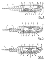
- einen Längsschnitt entsprechend der Linie ll-ll in Fig. 1 durch den montierten Schalter in Kontaktstellung des Bimetalls.
- Fig. 3
- eine Darstellung analog Fig. 2 bei in seine maximale Auslösestellung ausgeschwenktem Handauslöser und dementsprechend geöffnetem Schalter.
- Fig. 4
- den Schalter in Auslösestellung gemäß Fig. 3 bei losgelassenem Handauslöser.
- Fig. 5-7
- vergrößerte Ausschnittdarstellungen der Kontakt- und Handauslösebereiche des Schalters nach Fig. 2-4.
- Fig. 8
- eine modifizierte Ausführungsform des Handauslösers 29.
- 1
- Sockelteil
- 2
- Flachstecker
- 3
- Flachstecker
- 4
- inneres Ende
- 5
- inneres Ende
- 6
- Gehäusedeckfläche
- 7
- Gehäusedeckfläche
- 8
- Gehäusekappe
- 9
- Längsrichtung
- 10
- Fixieröffnung
- 11
- Fixierzahn
- 12
- Bimetall-Sprungscheibe
- 13
- Fixierende
- 14
- Fixierpunkt
- 15
- Bewegungsende
- 16
- Gegenkontakt
- 17
- Bewegungskontakt
- 18
- Trennschieber
- 19
- Druckfeder
- 20
- Ende
- 21
- Stützfläche
- 22
- Zentrierdorn
- 23
- Schenkel
- 24
- Druckende
- 25
- Kontaktöffnungsricht.
- 26
- Anschlag
- 27
- Führungsausnehmung
- 28
- Öffnung
- 29
- Handauslöser
- 30
- Flachseite, Boden
- 31
- Auslösearm
- 32
- Lagerachse
- 33
- Betätigungsarm
- 34
- Haltewange
- 35
- Haltewange
- 36
- Gehäusedurchtrittsöffnung
- 37
- Fixierschenkel
- 38
- Haltenase
- 39
- Gehäuseanschlag
- 40
- Querhaupt
- 41
- Lagerschale
- 42
- Auslöseschwenkung
- 43
- Gegenanschlagfläche
- 44
- Schwenkanschlag
- 45
- Kopffläche
- 46
- Betätigungssporn
- 47
- Drehrichtung
- 48
- Krafteinwirkung
- 49
- Krafteinwirkung
Claims (14)
- Schutzschalter zur Absicherung der Stromkreise von Kraftfahrzeugen, .
mit einem zur raumsparenden Aneinanderreihung flachquaderähnlichen Isolierstoffgehäuse und dieses mit zwei zueinander im Wesentlichen parallelen Deckflächen (6,7),dadurch gekennzeichnet,wobei aus einer Gehäuseseitenwand mit ihrer Flachebene parallell zu den beiden Gehäusedeckflächen (6,7) ausgerichtete Flachstecker (2,3) für die Kontaktierung mit einem Flachsicherungshalter hinausstehen,wobei die von den Flachsteckern (2,3) durchsetzte Gehäuseseitenwand durch ein die Flachstecker (2,3) tragendes Sockelteil (1) gebildet ist, während die anderen Gehäusewände Teile einer auf das Sockelteil (1) aufgeschobenen, insbesondere mit diesem verschnappten, die Schalterfunktionsteile umgebenden Gehäusekappe (8) sind undwobei die Flachstecker (2,3) mit ihren gehäuseseitigen Enden nebeneinanderstehend in den Gehäuseinnenraum hineinragen und durch eine am einem Flachstecker (2) fixierte, bei Überstrom die Kontaktierung öffnende Bimetall-Sprungscheibe (12) miteinander verbunden sind.dass die Gehäusekappe (8) an ihrem in Montagestellung dem Sockelteil (1) gegenüberliegenden Boden (30) eine Durchtrittsöffnung (36) für einen die Bimetall-Sprungscheibe (12) aus ihrer Kontaktierungsstellung aushebelnden Handauslöser (29) aufweist,dass die Durchtrittsöffnung eine quer zur Durchtrittsrichtung verlaufende, parallel zur Erstreckungsebene der Bimetall-Sprungscheibe (12) ausgerichtete und einstückig an die Gehäusekappe (8) angeformte Lagerachse (32) für den Handauslöser (29) enthält unddass der Handauslöser (29) derart von außen auf die Lagerachse (32) aufgeschnappt ist, dass er in Aufschnappstellung nach Art eines zweiarmigen Hebels einerseits die Bimetall-Sprungscheibe (12) mit einem in den Schalterinnenraum hineinragenden Auslösearm (31) zu deren wahlweiser Beaufschlagung in Kontakt-Öffnungsrichtung untergreift und andererseits mit einem Betätigungsende (33) über die durch den Boden der Gehäusekappe (8) gebildete Gehäuseseitenwand (30) nach außen hinaussteht. - Schutzschalter nach Anspruch 1,
gekennzeichnet durch
einen im Gehäuseinnenraum angeordneten, bei Kontaktöffnung infolge Federdrukkes zwischen die Kontakte (16,17) hineinfahrenden und diese voneinander distanzierenden Trennschieber (18), der über ein neben der Gehäusedurchtrittsöffnung (36) für den Handauslöser (29) aus derselben Gehäuseseite (30) wie der Handauslöser (29) herausstehendes Druckende (24) aus seiner Trennstellung zwischen den Kontakten (16,17) gegen den Federdruck zurückstoßbar ist. - Schutzschalter nach Anspruch 1 oder 2,
dadurch gekennzeichnet, dass der Handauslöser (29) ein einstückiges, etwa U-förmig gestaltetes Isolierstoffteil ist, welches mit seinem beiden U-Schenkeln die Lagerachse (32) form-und kraftschlüssig umfasst und dessen die Bimetall-Sprungscheibe untergreifender U-Schenkel den Auslösearm (31) bildet. - Schutzschalter nach Anspruch 3,
dadurch gekennzeichnet, dass der nicht den Auslösearm (31) bildende, andere U-Schenkel des Handauslösers (29) als Fixierschenkel (37) mit einer in Montagestellung die Lagerachse (32) hintergreifenden, in Richtung auf den Auslöseschenkel (31) vorstehenden Haltenase (38) versehen ist. - Schutzschalter nach Anspruch 4,
gekennzeichnet durch
einen vom Fixierschenkel (37) nach außen abstehenden, die Einschublänge des Handauslösers (29) in das Gehäuse limitierenden Gehäuseanschlag (39). - Schutzschalter nach einem oder mehreren der vorhergehenden Ansprüche,
dadurch gekennzeichnet, dass das Querhaupt (40) der U-Form das außenliegende Betätigungsende des Betätigungsarmes (33) des Handauslösers (29) bildet. - Schutzschalter nach Anspruch 6,
dadurch gekennzeichnet, dass der den Auslösearm des Handauslösers (29) bildende U-Schenkel (31,37) etwa im Mittenbereich seiner Längserstreckung auf seiner Innenseite zur Bildung einer Lagerschale (41) für die Lagerachse (32) ausgemuldet ist. - Schutzschalter nach einem oder mehreren der vorhergehenden Ansprüche,
dadurch gekennzeichnet, dass der Handauslöser (29) mit seinen beiden U-Schenkeln (31,37) als integrierte Schnapper die Lagerachse (32) leicht federelastisch beaufschlagend umfasst. - Schutzschalter nach einem oder mehreren der vorhergehenden Ansprüche,
dadurch gekennzeichnet, dass die Lagerachse (32) eine bei der Auslöseschwenkung (42) des Handauslösers (29) deren U-Schenkel elastisch aufspreizende Querschnittsform aufweist derart, dass der durch die Aufspreizung gespeicherte elastische Federdruck als den Handauslöser (29) selbsttätig in seine Ausgangs-Schwenkstellung zurückschwenkender Rückstelldruck wirksam ist. - Schutzschalter nach Anspruch 9,
dadurch gekennzeichnet, dass die die U-Schenkel (31,37) in Auslöseschwenkstellung (Fig. 3,6) beaufschlagende Querschnittsabmessung der Lagerachse (32) größer ist als die die U-Schenkel (31,37) in Ruhestellung (Fig. 2,4,5,7,8) des Handauslösers (29) beaufschlagende Querschnittsabmessung. - Schutzschalter nach Anspruch 9 oder 10,
dadurch gekennzeichnet, dass der Handauslöser (29) ein einstückiges Kunststoffspritzteil ist. - Schutzschalter nach einem oder mehreren der vorhergehenden Ansprüche,
dadurch gekennzeichnet, dass der Handauslöser (29) an seiner Außenseite einen abstehenden Betätigungssporn (46) trägt, der gegenüber der Lagerachse (32) außermittig etwa im Bereich des Aufeinandertreffens der Linksrichtungen des Auslösearms (31) bzw. des Betätigungsarms (33) einerseits und des Querhauptes (40) andererseits positioniert ist. - Schutzschalter nach Anspruch 12,
dadurch gekennzeichnet, dass der Betätigungssporn (46) in den Längsrichtungen des Auslösearmes (31) bzw. des Betätigungsarmes (33) entgegengesetzter Richtung vom Querhaupt (40) absteht. - Schutzschalter nach einem oder mehreren der vorhergehenden Ansprüche,
gekennzeichnet durch
eine mit der Gehäusefarbe kontrastierende Farbgebung des Handauslösers (29) insbesondere analog den Sicherungsfarben nach DIN72581-3 entsprechend unterschiedlichen Stromstärken des jeweiligen abzusichernden Stromkreises.
Applications Claiming Priority (3)
| Application Number | Priority Date | Filing Date | Title |
|---|---|---|---|
| DE19856707 | 1998-12-09 | ||
| DE19856707A DE19856707A1 (de) | 1998-12-09 | 1998-12-09 | Schutzschalter zur Absicherung von Stromkreisen |
| PCT/EP1999/008501 WO2000034971A1 (de) | 1998-12-09 | 1999-11-05 | Schutzschalter zur absicherung von stromkreisen in strassenfahrzeugen |
Publications (2)
| Publication Number | Publication Date |
|---|---|
| EP1141987A1 EP1141987A1 (de) | 2001-10-10 |
| EP1141987B1 true EP1141987B1 (de) | 2002-10-16 |
Family
ID=7890453
Family Applications (1)
| Application Number | Title | Priority Date | Filing Date |
|---|---|---|---|
| EP99968780A Expired - Lifetime EP1141987B1 (de) | 1998-12-09 | 1999-11-05 | Schutzschalter zur absicherung von stromkreisen in strassenfahrzeugen |
Country Status (8)
| Country | Link |
|---|---|
| US (1) | US6590489B1 (de) |
| EP (1) | EP1141987B1 (de) |
| JP (1) | JP4205862B2 (de) |
| KR (1) | KR100532791B1 (de) |
| CN (1) | CN1184660C (de) |
| AT (1) | ATE226357T1 (de) |
| DE (2) | DE19856707A1 (de) |
| WO (1) | WO2000034971A1 (de) |
Families Citing this family (24)
| Publication number | Priority date | Publication date | Assignee | Title |
|---|---|---|---|---|
| US7324876B2 (en) | 2001-07-10 | 2008-01-29 | Yingco Electronic Inc. | System for remotely controlling energy distribution at local sites |
| US7265652B2 (en) * | 2001-07-10 | 2007-09-04 | Yingco Electronic Inc. | Controllable electronic switch |
| US6825750B2 (en) * | 2001-07-10 | 2004-11-30 | Yingco Electronic Inc. | Controllable electronic switch with interposable non-conductive element to break circuit path |
| US6707368B2 (en) * | 2001-07-18 | 2004-03-16 | Cooper Technologies Company | Manually trippable circuit breaker |
| US6744345B2 (en) * | 2002-05-06 | 2004-06-01 | Cooper Technologies | Mid-range circuit breaker |
| US7071809B2 (en) * | 2002-11-25 | 2006-07-04 | Honeywell International Inc. | Thermal fuse containing bimetallic sensing element |
| DE202005007220U1 (de) * | 2005-05-06 | 2006-09-21 | Ellenberger & Poensgen Gmbh | Schutzschaltersystem |
| US7382223B2 (en) * | 2005-11-21 | 2008-06-03 | Sensata Technologies, Inc. | Thermal circuit breaker |
| US7405645B2 (en) * | 2006-04-20 | 2008-07-29 | Sensata Technologies, Inc. | Thermally activated circuit interrupter |
| DE102008049507A1 (de) | 2008-09-29 | 2010-04-01 | Ellenberger & Poensgen Gmbh | Miniatur-Schutzschalter |
| JP4906881B2 (ja) * | 2009-03-27 | 2012-03-28 | 富士電機機器制御株式会社 | 熱動形過負荷継電器 |
| RU2553280C2 (ru) | 2010-09-24 | 2015-06-10 | Элленбергер Унд Поенсген Гмбх | Миниатюрный предохранительный выключатель |
| US8941461B2 (en) * | 2011-02-02 | 2015-01-27 | Tyco Electronics Corporation | Three-function reflowable circuit protection device |
| US9455106B2 (en) | 2011-02-02 | 2016-09-27 | Littelfuse, Inc. | Three-function reflowable circuit protection device |
| DE102012024608B4 (de) * | 2012-12-15 | 2015-04-16 | Ellenberger & Poensgen Gmbh | Schutzschalter und Adapter für einen Schutzschalter |
| DE102015001945A1 (de) | 2015-02-16 | 2016-08-18 | Ellenberger & Poensgen Gmbh | Schutzschalter und Verfahren zu dessen Betrieb |
| WO2019142212A1 (en) * | 2018-01-16 | 2019-07-25 | Hero MotoCorp Limited | Switch device |
| DE102018100890B3 (de) * | 2018-01-16 | 2019-07-18 | Marcel P. HOFSAESS | Temperaturabhängiger Schalter |
| DE102019112074B4 (de) * | 2019-05-09 | 2020-12-17 | Marcel P. HOFSAESS | Temperaturabhängiger Schalter |
| US10796872B1 (en) * | 2019-09-01 | 2020-10-06 | Kuoyuh W.L. Enterprise Co., Ltd. | Vehicle circuit breaker |
| DE102019125452B4 (de) * | 2019-09-20 | 2021-04-22 | Marcel P. HOFSAESS | Temperaturabhängiger Schalter |
| DE102019125451B4 (de) * | 2019-09-20 | 2021-04-08 | Marcel P. HOFSAESS | Temperaturabhängiger Schalter |
| CN114121565A (zh) * | 2021-11-29 | 2022-03-01 | 浙江中亿豪科技有限公司 | 一种断路器的弹簧式隔离灭弧机构 |
| FR3142282B1 (fr) * | 2022-11-21 | 2025-02-14 | Safran Electrical & Power | Contacteur de puissance a ecran de clarification d’arc electrique et aeronef comportant un tel contacteur de puissance |
Family Cites Families (17)
| Publication number | Priority date | Publication date | Assignee | Title |
|---|---|---|---|---|
| FR998730A (fr) * | 1949-10-06 | 1952-01-22 | Ile D Etudes Electro Mecanique | Dispositif de commande de circuit électrique |
| DE1091205B (de) | 1959-08-20 | 1960-10-20 | Licentia Gmbh | Kleinselbstschalter in Schalenbauweise mit Handausloesung |
| DE1099624B (de) * | 1959-11-23 | 1961-02-16 | Licentia Gmbh | Kleinselbstschalter in Schalenbauweise mit Handausloesung |
| DE1805368A1 (de) * | 1967-11-15 | 1969-05-29 | Texas Instruments Inc | Automatischer Schalter |
| CH647094A5 (en) * | 1979-11-09 | 1984-12-28 | Weber Ag Fab Elektro | Two-pole protective circuit breaker with thermal tripping |
| US4363016A (en) * | 1981-06-03 | 1982-12-07 | Amf Incorporated | Circuit breaker |
| DE3424089A1 (de) * | 1983-08-19 | 1985-03-07 | Weber AG Fabrik elektrotechnischer Artikel und Apparate, Emmenbrücke | Druckknopfbetaetigter ueberstromschalter |
| DE3342144A1 (de) * | 1983-11-22 | 1985-05-30 | Ellenberger & Poensgen Gmbh, 8503 Altdorf | Druckknopfbetaetigter ueberstromschutzschalter |
| DE8521611U1 (de) * | 1985-07-26 | 1988-10-20 | Ellenberger & Poensgen Gmbh, 8503 Altdorf | Druckknopfbetätigter Überstromschutzschalter |
| DE8522254U1 (de) * | 1985-08-02 | 1985-09-26 | Ellenberger & Poensgen Gmbh, 8503 Altdorf | Überstromschutzschalter |
| DE3786492T2 (de) * | 1986-05-26 | 1993-11-18 | Matsushita Electric Works Ltd | Stromkreisunterbrecher. |
| DE8626325U1 (de) * | 1986-10-02 | 1987-01-02 | Ellenberger & Poensgen Gmbh, 8503 Altdorf | Überstromschutzschalter |
| US4814739A (en) * | 1987-12-18 | 1989-03-21 | Eaton Corporation | Combination push/pull electric switch and circuit breaker |
| DE8904063U1 (de) * | 1989-04-03 | 1989-06-22 | Ellenberger & Poensgen Gmbh, 8503 Altdorf | Druckknopfbetätigter Überstromschutzschalter |
| US5742219A (en) * | 1994-04-28 | 1998-04-21 | Siemens Electromechanical Components, Inc. | Switchable circuit breaker |
| US5854585A (en) * | 1997-04-10 | 1998-12-29 | Texas Instruments Incorporated | Manual reset electrical equipment protector apparatus |
| US5861794A (en) * | 1998-05-04 | 1999-01-19 | Texas Instruments Incorporated | Thermal circuit breaker apparatus |
-
1998
- 1998-12-09 DE DE19856707A patent/DE19856707A1/de not_active Withdrawn
-
1999
- 1999-11-05 DE DE59903125T patent/DE59903125D1/de not_active Expired - Lifetime
- 1999-11-05 US US09/857,806 patent/US6590489B1/en not_active Expired - Lifetime
- 1999-11-05 EP EP99968780A patent/EP1141987B1/de not_active Expired - Lifetime
- 1999-11-05 CN CNB99812351XA patent/CN1184660C/zh not_active Expired - Fee Related
- 1999-11-05 KR KR10-2001-7005500A patent/KR100532791B1/ko not_active Expired - Fee Related
- 1999-11-05 JP JP2000587347A patent/JP4205862B2/ja not_active Expired - Fee Related
- 1999-11-05 WO PCT/EP1999/008501 patent/WO2000034971A1/de not_active Ceased
- 1999-11-05 AT AT99968780T patent/ATE226357T1/de active
Also Published As
| Publication number | Publication date |
|---|---|
| CN1324493A (zh) | 2001-11-28 |
| WO2000034971A1 (de) | 2000-06-15 |
| DE19856707A1 (de) | 2000-06-21 |
| EP1141987A1 (de) | 2001-10-10 |
| ATE226357T1 (de) | 2002-11-15 |
| DE59903125D1 (de) | 2002-11-21 |
| US6590489B1 (en) | 2003-07-08 |
| CN1184660C (zh) | 2005-01-12 |
| JP4205862B2 (ja) | 2009-01-07 |
| KR20010089387A (ko) | 2001-10-06 |
| JP2002532826A (ja) | 2002-10-02 |
| KR100532791B1 (ko) | 2005-12-02 |
Similar Documents
| Publication | Publication Date | Title |
|---|---|---|
| EP1141987A1 (de) | Schutzschalter zur absicherung von stromkreisen in strassenfahrzeugen | |
| DE3834980C2 (de) | Anschlußanordnung für einen Schalter mit Formgehäuse | |
| CH647094A5 (en) | Two-pole protective circuit breaker with thermal tripping | |
| EP0680065B1 (de) | Überlast-Schutzschalter | |
| EP0151692B1 (de) | Druckknopfbetätigter Überstromschutzschalter | |
| DE3323474C2 (de) | Stromkreisunterbrecher | |
| AT400781B (de) | Überspannungsschutzvorrichtung | |
| EP0391086B1 (de) | Druckknopfbetätigter Ueberstromschutzschalter | |
| EP0211282B1 (de) | Überstromschutzschalter | |
| DE102007015794B4 (de) | Kontaktschiebereinheit für eine Schalteinheit, insbesondere einen Leistungsschalter, aufweisend einen Kontaktschieber und ein Schaltstück | |
| EP1949501B1 (de) | Schaltgerät | |
| EP1784847B1 (de) | Elektrisches installationsgerät | |
| DE9403259U1 (de) | Gehäuseaufbau für einen Niederspannungs-Schutzschalter mit Hilfsschalterblock | |
| DE2558942C2 (de) | Schalter mit einem kippbaren Schalthebel | |
| EP0172374B1 (de) | Ein- oder mehrpoliger Überstromschutzschalter mit integrierter Signalkontaktstelle | |
| DE10055035C2 (de) | Lasttrennschalter mit mindestens einem Sicherungshalter | |
| EP1728260A1 (de) | Schaltwerk für ein elektrisches installationsschaltgerät | |
| DE102004018275A1 (de) | Schaltvorrichtung | |
| WO2008067987A1 (de) | Schaltvorrichtung mit drehgriff | |
| EP1547112B1 (de) | Elektromagnetisches schaltgerät | |
| EP0849759B1 (de) | Installationsschaltgerät | |
| EP0862784B1 (de) | Überstromschutzschalter | |
| DE3734396A1 (de) | Elektrisches schaltgeraet | |
| EP1676288B1 (de) | Installationsgerät | |
| DE102012201677A1 (de) | Elektrisches Schaltgerät, insbesondere Leistungsschalter |
Legal Events
| Date | Code | Title | Description |
|---|---|---|---|
| PUAI | Public reference made under article 153(3) epc to a published international application that has entered the european phase |
Free format text: ORIGINAL CODE: 0009012 |
|
| 17P | Request for examination filed |
Effective date: 20010519 |
|
| AK | Designated contracting states |
Kind code of ref document: A1 Designated state(s): AT BE CH CY DE DK ES FI FR GB GR IE IT LI LU MC NL PT SE |
|
| GRAG | Despatch of communication of intention to grant |
Free format text: ORIGINAL CODE: EPIDOS AGRA |
|
| 17Q | First examination report despatched |
Effective date: 20011220 |
|
| GRAG | Despatch of communication of intention to grant |
Free format text: ORIGINAL CODE: EPIDOS AGRA |
|
| GRAG | Despatch of communication of intention to grant |
Free format text: ORIGINAL CODE: EPIDOS AGRA |
|
| GRAH | Despatch of communication of intention to grant a patent |
Free format text: ORIGINAL CODE: EPIDOS IGRA |
|
| GRAH | Despatch of communication of intention to grant a patent |
Free format text: ORIGINAL CODE: EPIDOS IGRA |
|
| GRAA | (expected) grant |
Free format text: ORIGINAL CODE: 0009210 |
|
| AK | Designated contracting states |
Kind code of ref document: B1 Designated state(s): AT BE CH CY DE DK ES FI FR GB GR IE IT LI LU MC NL PT SE |
|
| PG25 | Lapsed in a contracting state [announced via postgrant information from national office to epo] |
Ref country code: IT Free format text: LAPSE BECAUSE OF FAILURE TO SUBMIT A TRANSLATION OF THE DESCRIPTION OR TO PAY THE FEE WITHIN THE PRESCRIBED TIME-LIMIT;WARNING: LAPSES OF ITALIAN PATENTS WITH EFFECTIVE DATE BEFORE 2007 MAY HAVE OCCURRED AT ANY TIME BEFORE 2007. THE CORRECT EFFECTIVE DATE MAY BE DIFFERENT FROM THE ONE RECORDED. Effective date: 20021016 Ref country code: IE Free format text: LAPSE BECAUSE OF FAILURE TO SUBMIT A TRANSLATION OF THE DESCRIPTION OR TO PAY THE FEE WITHIN THE PRESCRIBED TIME-LIMIT Effective date: 20021016 Ref country code: GR Free format text: LAPSE BECAUSE OF FAILURE TO SUBMIT A TRANSLATION OF THE DESCRIPTION OR TO PAY THE FEE WITHIN THE PRESCRIBED TIME-LIMIT Effective date: 20021016 Ref country code: FI Free format text: LAPSE BECAUSE OF FAILURE TO SUBMIT A TRANSLATION OF THE DESCRIPTION OR TO PAY THE FEE WITHIN THE PRESCRIBED TIME-LIMIT Effective date: 20021016 |
|
| REF | Corresponds to: |
Ref document number: 226357 Country of ref document: AT Date of ref document: 20021115 Kind code of ref document: T |
|
| REG | Reference to a national code |
Ref country code: GB Ref legal event code: FG4D Free format text: NOT ENGLISH |
|
| REG | Reference to a national code |
Ref country code: CH Ref legal event code: EP |
|
| REG | Reference to a national code |
Ref country code: IE Ref legal event code: FG4D Free format text: GERMAN |
|
| REF | Corresponds to: |
Ref document number: 59903125 Country of ref document: DE Date of ref document: 20021121 |
|
| REG | Reference to a national code |
Ref country code: CH Ref legal event code: NV Representative=s name: E. BLUM & CO. PATENTANWAELTE |
|
| PG25 | Lapsed in a contracting state [announced via postgrant information from national office to epo] |
Ref country code: CY Free format text: LAPSE BECAUSE OF FAILURE TO SUBMIT A TRANSLATION OF THE DESCRIPTION OR TO PAY THE FEE WITHIN THE PRESCRIBED TIME-LIMIT Effective date: 20021130 Ref country code: BE Free format text: LAPSE BECAUSE OF NON-PAYMENT OF DUE FEES Effective date: 20021130 |
|
| PG25 | Lapsed in a contracting state [announced via postgrant information from national office to epo] |
Ref country code: PT Free format text: LAPSE BECAUSE OF FAILURE TO SUBMIT A TRANSLATION OF THE DESCRIPTION OR TO PAY THE FEE WITHIN THE PRESCRIBED TIME-LIMIT Effective date: 20030116 Ref country code: DK Free format text: LAPSE BECAUSE OF FAILURE TO SUBMIT A TRANSLATION OF THE DESCRIPTION OR TO PAY THE FEE WITHIN THE PRESCRIBED TIME-LIMIT Effective date: 20030116 |
|
| GBT | Gb: translation of ep patent filed (gb section 77(6)(a)/1977) |
Effective date: 20030129 |
|
| PG25 | Lapsed in a contracting state [announced via postgrant information from national office to epo] |
Ref country code: ES Free format text: LAPSE BECAUSE OF FAILURE TO SUBMIT A TRANSLATION OF THE DESCRIPTION OR TO PAY THE FEE WITHIN THE PRESCRIBED TIME-LIMIT Effective date: 20030429 |
|
| ET | Fr: translation filed | ||
| BERE | Be: lapsed |
Owner name: *ELLENBERGER & POENSGEN G.M.B.H. Effective date: 20021130 |
|
| PG25 | Lapsed in a contracting state [announced via postgrant information from national office to epo] |
Ref country code: MC Free format text: LAPSE BECAUSE OF NON-PAYMENT OF DUE FEES Effective date: 20030601 |
|
| REG | Reference to a national code |
Ref country code: IE Ref legal event code: FD4D Ref document number: 1141987E Country of ref document: IE |
|
| PLBE | No opposition filed within time limit |
Free format text: ORIGINAL CODE: 0009261 |
|
| STAA | Information on the status of an ep patent application or granted ep patent |
Free format text: STATUS: NO OPPOSITION FILED WITHIN TIME LIMIT |
|
| 26N | No opposition filed |
Effective date: 20030717 |
|
| REG | Reference to a national code |
Ref country code: CH Ref legal event code: PFA Owner name: ELLENBERGER & POENSGEN GMBH Free format text: ELLENBERGER & POENSGEN GMBH#INDUSTRIESTRASSE 2-8#D-90518 ALTDORF (DE) -TRANSFER TO- ELLENBERGER & POENSGEN GMBH#INDUSTRIESTRASSE 2-8#D-90518 ALTDORF (DE) |
|
| REG | Reference to a national code |
Ref country code: FR Ref legal event code: PLFP Year of fee payment: 17 |
|
| PGFP | Annual fee paid to national office [announced via postgrant information from national office to epo] |
Ref country code: LU Payment date: 20151125 Year of fee payment: 17 Ref country code: CH Payment date: 20151123 Year of fee payment: 17 Ref country code: GB Payment date: 20151123 Year of fee payment: 17 |
|
| PGFP | Annual fee paid to national office [announced via postgrant information from national office to epo] |
Ref country code: AT Payment date: 20151120 Year of fee payment: 17 Ref country code: SE Payment date: 20151123 Year of fee payment: 17 Ref country code: NL Payment date: 20151124 Year of fee payment: 17 Ref country code: FR Payment date: 20151124 Year of fee payment: 17 |
|
| REG | Reference to a national code |
Ref country code: CH Ref legal event code: PL |
|
| REG | Reference to a national code |
Ref country code: SE Ref legal event code: EUG |
|
| REG | Reference to a national code |
Ref country code: NL Ref legal event code: MM Effective date: 20161201 |
|
| REG | Reference to a national code |
Ref country code: AT Ref legal event code: MM01 Ref document number: 226357 Country of ref document: AT Kind code of ref document: T Effective date: 20161105 |
|
| GBPC | Gb: european patent ceased through non-payment of renewal fee |
Effective date: 20161105 |
|
| PG25 | Lapsed in a contracting state [announced via postgrant information from national office to epo] |
Ref country code: LI Free format text: LAPSE BECAUSE OF NON-PAYMENT OF DUE FEES Effective date: 20161130 Ref country code: CH Free format text: LAPSE BECAUSE OF NON-PAYMENT OF DUE FEES Effective date: 20161130 |
|
| REG | Reference to a national code |
Ref country code: FR Ref legal event code: ST Effective date: 20170731 |
|
| PG25 | Lapsed in a contracting state [announced via postgrant information from national office to epo] |
Ref country code: AT Free format text: LAPSE BECAUSE OF NON-PAYMENT OF DUE FEES Effective date: 20161105 Ref country code: SE Free format text: LAPSE BECAUSE OF NON-PAYMENT OF DUE FEES Effective date: 20161106 |
|
| PG25 | Lapsed in a contracting state [announced via postgrant information from national office to epo] |
Ref country code: NL Free format text: LAPSE BECAUSE OF NON-PAYMENT OF DUE FEES Effective date: 20161201 Ref country code: LU Free format text: LAPSE BECAUSE OF NON-PAYMENT OF DUE FEES Effective date: 20161130 |
|
| PG25 | Lapsed in a contracting state [announced via postgrant information from national office to epo] |
Ref country code: FR Free format text: LAPSE BECAUSE OF NON-PAYMENT OF DUE FEES Effective date: 20161130 |
|
| PG25 | Lapsed in a contracting state [announced via postgrant information from national office to epo] |
Ref country code: GB Free format text: LAPSE BECAUSE OF NON-PAYMENT OF DUE FEES Effective date: 20161105 |
|
| PGFP | Annual fee paid to national office [announced via postgrant information from national office to epo] |
Ref country code: DE Payment date: 20171124 Year of fee payment: 19 |
|
| REG | Reference to a national code |
Ref country code: DE Ref legal event code: R119 Ref document number: 59903125 Country of ref document: DE |
|
| PG25 | Lapsed in a contracting state [announced via postgrant information from national office to epo] |
Ref country code: DE Free format text: LAPSE BECAUSE OF NON-PAYMENT OF DUE FEES Effective date: 20190601 |