EP1142189B1 - System und verfahren zur erreichung von synchronisation mit zwei detektionsschwellen - Google Patents
System und verfahren zur erreichung von synchronisation mit zwei detektionsschwellen Download PDFInfo
- Publication number
- EP1142189B1 EP1142189B1 EP99961706A EP99961706A EP1142189B1 EP 1142189 B1 EP1142189 B1 EP 1142189B1 EP 99961706 A EP99961706 A EP 99961706A EP 99961706 A EP99961706 A EP 99961706A EP 1142189 B1 EP1142189 B1 EP 1142189B1
- Authority
- EP
- European Patent Office
- Prior art keywords
- samples
- batch
- syncword
- group
- detection threshold
- Prior art date
- Legal status (The legal status is an assumption and is not a legal conclusion. Google has not performed a legal analysis and makes no representation as to the accuracy of the status listed.)
- Expired - Lifetime
Links
- 238000000034 method Methods 0.000 title claims abstract description 83
- 238000001514 detection method Methods 0.000 title claims abstract description 75
- 230000009977 dual effect Effects 0.000 title 1
- 238000005070 sampling Methods 0.000 claims description 32
- 230000001413 cellular effect Effects 0.000 description 10
- 230000002596 correlated effect Effects 0.000 description 10
- 230000000694 effects Effects 0.000 description 7
- 230000003466 anti-cipated effect Effects 0.000 description 3
- 238000004590 computer program Methods 0.000 description 2
- 230000006735 deficit Effects 0.000 description 2
- 238000010586 diagram Methods 0.000 description 2
- 230000010363 phase shift Effects 0.000 description 2
- 230000002411 adverse Effects 0.000 description 1
- 230000003679 aging effect Effects 0.000 description 1
- 238000006243 chemical reaction Methods 0.000 description 1
- 230000000875 corresponding effect Effects 0.000 description 1
- 230000007423 decrease Effects 0.000 description 1
- 238000005562 fading Methods 0.000 description 1
- 230000005404 monopole Effects 0.000 description 1
- 230000001151 other effect Effects 0.000 description 1
Images


Classifications
-
- H—ELECTRICITY
- H04—ELECTRIC COMMUNICATION TECHNIQUE
- H04B—TRANSMISSION
- H04B7/00—Radio transmission systems, i.e. using radiation field
- H04B7/14—Relay systems
- H04B7/15—Active relay systems
- H04B7/204—Multiple access
- H04B7/212—Time-division multiple access [TDMA]
-
- H—ELECTRICITY
- H04—ELECTRIC COMMUNICATION TECHNIQUE
- H04L—TRANSMISSION OF DIGITAL INFORMATION, e.g. TELEGRAPHIC COMMUNICATION
- H04L7/00—Arrangements for synchronising receiver with transmitter
- H04L7/04—Speed or phase control by synchronisation signals
- H04L7/041—Speed or phase control by synchronisation signals using special codes as synchronising signal
- H04L7/042—Detectors therefor, e.g. correlators, state machines
-
- H—ELECTRICITY
- H04—ELECTRIC COMMUNICATION TECHNIQUE
- H04B—TRANSMISSION
- H04B7/00—Radio transmission systems, i.e. using radiation field
- H04B7/24—Radio transmission systems, i.e. using radiation field for communication between two or more posts
- H04B7/26—Radio transmission systems, i.e. using radiation field for communication between two or more posts at least one of which is mobile
- H04B7/2662—Arrangements for Wireless System Synchronisation
- H04B7/2671—Arrangements for Wireless Time-Division Multiple Access [TDMA] System Synchronisation
- H04B7/2678—Time synchronisation
- H04B7/2681—Synchronisation of a mobile station with one base station
-
- H—ELECTRICITY
- H04—ELECTRIC COMMUNICATION TECHNIQUE
- H04W—WIRELESS COMMUNICATION NETWORKS
- H04W56/00—Synchronisation arrangements
-
- H—ELECTRICITY
- H04—ELECTRIC COMMUNICATION TECHNIQUE
- H04B—TRANSMISSION
- H04B7/00—Radio transmission systems, i.e. using radiation field
- H04B7/24—Radio transmission systems, i.e. using radiation field for communication between two or more posts
- H04B7/26—Radio transmission systems, i.e. using radiation field for communication between two or more posts at least one of which is mobile
- H04B7/2662—Arrangements for Wireless System Synchronisation
- H04B7/2665—Arrangements for Wireless Frequency Division Multiple Access [FDMA] System Synchronisation
-
- H—ELECTRICITY
- H04—ELECTRIC COMMUNICATION TECHNIQUE
- H04W—WIRELESS COMMUNICATION NETWORKS
- H04W56/00—Synchronisation arrangements
- H04W56/0055—Synchronisation arrangements determining timing error of reception due to propagation delay
- H04W56/0065—Synchronisation arrangements determining timing error of reception due to propagation delay using measurement of signal travel time
- H04W56/007—Open loop measurement
- H04W56/0075—Open loop measurement based on arrival time vs. expected arrival time
- H04W56/0085—Open loop measurement based on arrival time vs. expected arrival time detecting a given structure in the signal
Definitions
- the present invention relates generally to systems and methods for acquiring channel synchronization and, more particularly, to systems and methods for acquiring such synchronization in time division multiple access communications systems.
- TDMA time division multiple access
- FDMA frequency division multiple access
- TDMA time division multiple access
- FDMA frequency division multiple access
- the users involved with a particular phone call in an ANSI-136 network access one of the available time slots on a specific frequency sub-band.
- up to six separate calls may occur simultaneously on any given sub-band, as the six sets of users share the sub-band by transmitting only during their assigned time slots.
- a user terminal tunes its transceiver to one of the sub-bands and acquires synchronization to a predetermined time slot in that sub-band.
- this synchronization is accomplished by determining the location of a synchronization sequence or "syncword.”
- a unique syncword is transmitted during each time slot, typically as the first few modulated symbols in the time slot or "burst.”
- DQPSK differential quadrature phase shift keyed
- ANSI-136 specifies up to six time slots per frequency sub-band, a total of six unique syncwords are specified, one for each of the TDMA time slots.
- a cellular terminal acquires synchronization via the following process.
- a "batch" typically comprises a total of 1408 samples, which corresponds to eight separate samples per symbol period over 176 consecutive symbol periods. Note that a batch of 176 symbols is typically used (instead of the 162 symbols which are transmitted during a time slot) to ensure that the 14-symbol syncword is not divided between the beginning and the end of the batch.
- the processor Upon receiving a batch of 1408 samples, the processor performs a series of correlations on the received batch of samples to determine which 14-symbol (112 sample) portion of the batch has the highest correlation with any one of the six, predefined, 14-symbol syncwords. This is typically accomplished by correlating the first 112 samples (samples 1-112 out of the 1408 sample batch) with each of the six syncwords, then correlating samples 2-113 with each of the six syncwords, and so on, until each consecutive group of 112 samples in the batch has been correlated with each of the six syncwords. This may require a total of 7,776 separate complex correlations. The results of these correlations are then compared to determine the location of the group of 112 samples which had the highest correlation energy with any of the six predefined syncwords.
- the local oscillators provided in many cellular telephones and other wireless communications terminals demonstrate some degree of error in frequency. This error may arise due to component tolerances, temperature changes, or aging or other effects, and may, in many instances, exceed several kHz or more. Additionally, local oscillators typically have varying settling time, which also may introduce a dynamic frequency error. The net effect of these frequency errors is to reduce the correlation energy detected when a group of received samples which generally correspond to a known syncword are correlated with that syncword. Such frequency effects are particularly problematic in FDMA/TDMA networks which have frequent hand-offs, a large number of frequency sub-bands, and/or low cost user terminals (which typically have less accurate local oscillators).
- the above described correlation process may be performed multiple times, with the batch of samples "pre-rotated” in phase a different amount on each iteration to adjust the frequency (and hence offset the frequency error).
- the batch of samples "pre-rotated” in phase may be adjusted by the frequency (and hence offset the frequency error).
- as many as thirteen iterations may be required in order to obtain correlations over a sufficient range of frequencies such that there is a high probability of detecting the syncword.
- the highest correlation energy obtained during the above described correlation process (which may involve over 100,000 complex correlations) is then compared to a fixed syncword detection threshold. If this correlation energy value does not exceed the fixed threshold, the terminal will typically repeat the process with one or more new batches of digitized samples. Ultimately, if none of these repeated efforts to acquire synchronization are successful, the terminal will conclude that no base station is transmitting on that sub-band (or there is too much noise to acquire it), and synchronization on a different frequency sub-band will then be attempted.
- the detection threshold typically is set low enough to allow detection of syncword patterns during periods of channel impairment.
- the microprocessor adjusts the local oscillator frequency based on the phase pre-rotation (frequency error) associated with the identified syncword, and receives and samples a second segment of the signal transmitted by the base station so as to provide a second batch of digitized samples. Typically, the timing for the reception of this second batch of samples is adjusted so that the identified syncword appears as the first group of samples in the batch.
- the above-described process is repeated in order to determine a new phase pre-rotation, and this process continues until the phase pre-rotation (the frequency error) is within a specified threshold.
- the correlation process may be repeated one or more additional times to confirm the presence of a syncword in two or more bursts to reduce the possibility of detecting false synchronization patterns. If initial synchronization is not accomplished within a predetermined amount of time, a failure may be declared on that frequency sub-band.
- the above-described synchronization method may require significant time. This adversely affects both the time a user must wait to complete calls and the "muting" time which occurs when a cellular user switches communications between two different base stations.
- Another traditional method which requires less processing time, performs complex correlations using only one sample per symbol period. Thus, for example, if the received signal is sampled at a rate of eight samples per symbol, the first correlation would use samples 1, 9, 17, . . . 105; the second correlation would use samples 9, 17, 25, . . . 113; and so on. This method reduces the processing time by nearly an order of magnitude as compared to the method described above (972 correlations per frequency rotation versus 7,776).
- this method has the limitation that the correlation energies may be lower due to sampling the received signal at sub-optimal sampling positions (selecting samples in-between symbol energy peaks). Because of the anticipated lower correlation energies, the detection threshold typically is lowered. Unfortunately, such a lower threshold increases the probability of detecting false synchronization patterns due to frequency error and other signal impairments such as noise and Rayleigh fading. These "false positives" can also significantly increase the time required to acquire synchronization, as the user terminal must detect that a false acquisition has occurred (after it fails to locate syncwords during subsequent bursts) and repeat the synchronization process.
- U.S. Patent No. 5,373,536 to Dehner, Jr. et al. discloses a method of synchronizing to a signal that includes first performing a rough synchronization and then a fine synchronization. In this manner the bit clock may be adjusted so that subsequent data samples may be taken as close to bit center as possible.
- these systems and methods will work well with all syncword modulation types, and are capable of accommodating at least several kHz in frequency error due to component tolerances in the local oscillator and to the additional frequency error resulting during the settling of the local oscillator. Additionally, these systems and methods will preferably reduce the number of false positives which occur during the synchronization process.
- Another object of the present invention is to provide synchronization systems and methods which can tolerate both the frequency error and settling time characteristics common to low cost local oscillators.
- systems and methods for acquiring synchronization which initially correlate a batch of samples from a received signal which were sampled at a low sampling rate with one or more known syncwords to identify in the batch the group of samples with the highest correlation to any one of the syncwords. This highest value of the correlation energy is then compared to a relatively low detection threshold. If the correlation energy exceeds the relatively low detection threshold, one or more additional correlations are performed at "nearby" locations using a higher sampling rate and a more stringent detection threshold. In this manner it is possible to significantly reduce the total number of correlations that are used, as most of the correlations may be performed using relatively few samples per symbol.
- the systems and methods of the present invention can reduce the possibility that the detection algorithm incorrectly locates the presence of a syncword pattern (a "false positive"), and can further reduce acquisition time by halting the process upon identification of a sequence with a correlation energy which exceeds the higher detection threshold. Accordingly, the systems and methods of the present invention both improve the accuracy of the synchronization process while potentially significantly reducing the acquisition time.
- a method for locating a known multi-symbol syncword in a received signal is provided.
- a potential syncword is located in a first batch of samples of the received signal which has a correlation energy with the known syncword which exceeds a first detection threshold.
- a correlation energy for a group of samples in a second batch of samples of the received signal with the known syncword is determined, where the group of samples in the second batch of samples are selected based on the location of the potential syncword within the first batch of samples.
- the correlation energy associated with the group of samples in the second batch of samples is compared with a second detection threshold that is higher than the first detection threshold.
- the location of the known syncword may be identified based upon the comparison of the correlation energy associated with the group of samples in the second batch of samples with the second detection threshold.
- the potential syncword may be located by identifying the group of consecutive samples within the first batch of samples which has the highest correlation energy with the known syncword and by comparing the correlation energy associated with the identified group of consecutive samples with the first detection threshold.
- the location of the syncword may be identified as the group of samples in the second batch of samples which has a correlation energy that exceeds the second detection threshold.
- the first batch of samples may be obtained by sampling the received signal at a first sampling rate and the second batch of samples may be obtained by sampling the received signal at a second sampling rate that is higher than the first sampling rate.
- the group of samples in the second batch of samples may be selected to correspond to substantially the same group of symbols as the potential syncword.
- improved systems and methods for acquiring synchronization are provided which can reduce the time required to obtain synchronization and can increase the accuracy of the synchronization process.
- these systems and methods work with a variety of modulation schemes, are flexible with respect to varying channel conditions and further are capable of tolerating variations in component tolerances which impact the synchronization process such as local oscillator accuracy and settling time.
- Figure 1 depicts a cellular telephone communications network 10 in which the synchronization systems and methods of the present invention may be used. It will be understood in light of the present disclosure, however, that the systems and methods of the present invention have application beyond networks such as those depicted in Figure 1, and in fact may be suitable for use in any digital communications network in which acquisition of timing synchronization is required.
- a plurality of user terminals 12, 14, 16, 18, 20, 22 communicate with each other and other communications terminals (which are not pictured) via base stations 24, 26 that receive calls from various of the user terminals and retransmit the calls to other user terminals either directly, via other base stations, or via another telecommunications network (such as the conventional telephone network).
- the systems and methods of the present invention may be suitable for use in any digital communications network in which acquisition of timing synchronization is required.
- the methods are used in communications networks which use an FDMA/TDMA access format.
- Figure 2 illustrates the channel structure of an exemplary FDMA/TDMA network which provides up to a total of twelve channels.
- the radio frequency communications are transmitted over three separate FDMA frequency sub-bands 30, 35, 40. Each of these sub-bands are then further divided into four separate time-multiplexed channels 31, 32, 33, 34; 36, 37, 38, 39; 41, 42, 43, 44.
- this time multiplexing is accomplished by dividing the communications which are transmitted over the channel into a repeating series of "frames," wherein each frame is subdivided into up to four separate time slots.
- Each of these repeating time slots 31, 32, 33, 34; 36, 37, 38, 39; 41, 42, 43, 44 comprises a channel.
- a terminal which seeks to access a TDMA communications systems first acquires synchronization to one of the time slots which comprises a communications channel.
- the user terminals may acquire such synchronization by receiving a signal which is transmitted by the base station and identifying the location in that signal of a predefined sequence of symbols which comprise a known synchronization word or "syncword.”
- a unique syncword is typically provided for each separate time slot in a frequency sub-band, and the syncword is located at a predefined position within the time slot.
- the syncwords comprise unique sequences of 14 consecutive symbols which are implemented as the first 14 symbols of each 162 symbol time slot.
- ANSI-136 provides for dividing each of the frequency bands which carry communications into up to six separate time-mulitplexed channels, six unique synchronization sequences are provided. Once the user terminal identifies the location of a syncword, it is possible for the terminal to thereby synchronize its timing with the timing of the transmitting base station, thereby allowing the terminal to communicate in one of the predefined time slots.
- DQPSK differential quadrature phase shift keying modulation
- FIG. 3 A block diagram of one embodiment of a system 50 according to the present invention is illustrated in Figure 3.
- the system comprises a receive antenna 52, a radio frequency receiver 54, a digital signal processor 60 and a microprocessor 62.
- Receive antenna 52 may be any antenna suitable for receiving radio frequency signals, such as dipole, monopole, helix, and/or patch antennas, or any other of a wide variety of antennas suitable for wireless communications which are known to those of skill in the art.
- radio frequency receivers 54 which are suitable for use with the present invention are also known to those of skill in the art and hence will not be discussed further herein, except to note that the radio frequency receiver may include (or have associated with it) an analog-to-digital (“A/D”) converter 56 and a local oscillator 58.
- the local oscillator 58 is used to tune the radio frequency receiver 54 to a desired frequency at which the terminal will transmit and/or receive radio frequency signals, and the A/D converter 56 is used to digitize samples of any received signal for processing by the radio frequency receiver 54, digital signal processor 60, and/or microprocessor 62.
- a digital-to-analog (“D/A”) converter 61 may also be provided to facilitate control by the microprocessor 62 of burst timing and/or oscillator frequency.
- Digital signal processor 60 may be used to perform a series of correlations for identifying the portion of a received signal which correlates highly with one or more of the predefined syncwords.
- correlations may conveniently be performed using a digital signal processor, a variety of other hardware and/or software is available for performing such correlations, and any suitable method of performing such correlations may be employed with the present invention.
- the correlation may be performed using a general purpose microprocessor.
- microprocessor 62 may be used to facilitate control of the frequency of the local oscillator 58, particularly in FDMA/TDMA systems in which a user terminal may communicate at a variety of different frequencies. As indicated in Figure 3, microprocessor 62 may also be used to align burst timing after the syncword has been located.
- the number of correlations can be reduced significantly by sampling the received signal at a lower sampling rate (e.g. , at one sample per symbol as compared to the traditional eight samples per symbol), which automatically reduces the required number of correlations by almost an order of magnitude.
- a relatively low detection threshold i.e. , the correlation energy which, if exceeded, indicates the possible presence of a syncword
- a relatively high detection threshold is preferably used in evaluating whether or not the "retry" correlations indicate the presence of a syncword. The use of this higher threshold reduces the possibility that the method will incorrectly identify the presence of a syncword because of channel noise and/or intersymbol interference effects. Moreover, by using a relatively high detection threshold, it is also possible to have a large degree of confidence that a syncword has been found when the correlation energy associated with a group of samples exceeds the high detection threshold.
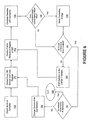
- FIGS. 4-6 are flowcharts illustrating various embodiments of the synchronization acquisition systems and methods of the present invention. It will be understood that the blocks in these flowcharts, and combinations of blocks in these flowcharts, can generally be implemented by general purpose computer hardware, special purpose computer hardware and/or via computer program instructions. If performed in software, the program instructions may be provided to a digital signal processor, microprocessor or the like such that the instructions which execute on the processor create means for implementing the functions specified in the flowchart block or blocks.
- the computer program instructions may be executed by a processor to cause a series of operational steps to be performed by the processor to produce a computer implemented process such that the instructions which execute on the processor provide steps for implementing the functions specified in the flowchart block or blocks. Accordingly, blocks of the flowchart illustrations support combinations of means for performing the specified functions, combinations of steps for performing the specified functions and program instruction means for performing the specified functions.
- the flow chart of Figure 4 illustrates one embodiment of the present invention.
- a portion of the radio frequency or other signal present in the frequency sub-band in which the terminal is attempting to acquire synchronization is received and then sampled (block 64 ).
- both the receiving and sampling are performed by a radio frequency receiver 54.
- Various groups of consecutive samples (which are of substantially the same length in symbols as the predefined syncword(s) used on that frequency sub-band) are then correlated with each of the syncwords (block 66 ) in order to identify the group of samples with the highest correlation energy to any of the predefined syncwords (block 68 ).
- the highest correlation energy value which is obtained through the correlations of block 66 and identified in block 68 is then compared to a relatively high detection threshold (block 70 ) . If the correlation energy exceeds this high threshold, the syncword is considered found and the information regarding the location of the syncword within the received sample batch may be provided to the radio frequency receiver 54 and/or microprocessor 62 so that the user terminal may align its timing with the timing of the other users communicating on the various time division mulitplexed channels (block 74 ). If the correlation energy associated with the identified group of samples, however, does not exceed the high threshold, then a second comparison is performed using a lower detection threshold (block 72 ).
- the user terminal may assume that the syncword has not been located (block 80 ). In this event, the terminal can reattempt acquisition using a new batch of samples, or can instead move to another frequency (in FDMA/TDMA communication systems) and attempt acquisition there. If the correlation energy, on the other hand, exceeds the lower detection threshold, the correlation energy for groups of consecutive samples which are close to or "nearby" the identified group of samples are calculated (block 76 ).
- the calculated correlation energy associated with these nearby groups of samples may then be compared to the high detection threshold (block 78 ), and based on the result of this comparison, the syncword will either be reported as found or as not found (blocks 74, 80 ).
- the relatively high detection threshold is set at a correlation energy of between 85% and 95%, and more preferably, the high detection threshold is established as a correlation energy of between 88% and 92%.
- the relatively low detection threshold is set at a correlation energy of between 65% and 75%, and, more preferably, is established as a correlation energy of between 68% and 72%.
- prior art methods of synchronization acquisition may use a detection threshold of approximately 80% correlation energy.
- the ideal relatively low and relatively high detection thresholds may vary significantly. Accordingly, the present invention is not intended to be limited to the above recited ranges for these parameters, which are only provided to serve as example ranges which may work well in typical communications systems.
- the groups of consecutive samples at "nearby" locations which are correlated with the syncwords in block 76 of Figure 4 comprise groups of samples which are offset from the group of samples identified in block 68 by less than one symbol position.
- two additional retry correlations may be performed - - one on the group of samples falling approximately one-half a symbol position in front of the group of samples identified in block 68, and the other group of samples falling approximately one-half a symbol position after the group of samples identified in block 68.
- more or less of these "retry" correlations may be performed.
- the radio frequency receiver 54 could receive and sample a second portion of the signal transmitted by the base station, timing the reception to correspond with the timing appropriate for the retry correlations, and use these samples for the retry correlations of block 76.
- both the initial and the retry correlations are performed on groups of consecutive samples.
- similar results may be obtained by performing these correlations on groups of nearly consecutive samples (e.g., a group of samples where a few samples are dropped), and hence the methods of the present invention are not limited to consecutive samples.
- a subset of the samples are used for the initial correlations (in the example above it was every eighth sample), that this subset of samples comprises its own batch of samples for determining whether or not samples are consecutive.
- a user terminal which is seeking to communicate over the network will typically need to tune its local oscillator 58 to one of the multiple frequency sub-bands at which channels are located, as well as acquire synchronization with a channel within that frequency sub-band.
- relatively inexpensive local oscillators are used in many user terminals, component tolerances will often introduce several kHz or more of error in the frequency setting, and additional frequency error may occur because of oscillator settling time. Typically, the magnitude of these errors increases the greater the change in frequency which is required.
- phase pre-rotations In order to compensate for local oscillator induced frequency error, it may be desirable to perform additional correlations where the phase of the complex samples of the received signal is pre-rotated, effectively modifying the frequency. Typically a phase rotation corresponding to a 300-1000 Hz frequency change is used. Depending on the anticipated range of frequency error, it may be necessary to perform correlations with as many as ten or more phase pre-rotations, to ensure that correlations are performed at a frequency relatively close to the center-frequency of the frequency sub-band.
- the number of pre-rotations may vary based on the extent to which the setting on the local oscillator is to be changed ( i.e ., the greater the frequency change, the greater the number of phase pre-rotations required).
- the number of phase pre-rotations or "steps" required is determined by reference to a look-up table which establishes the number of steps required based on the change in frequency contemplated.
- methods for acquiring channel synchronization in FDMA/TDMA communications systems which are subject to such local oscillator induced frequency error are provided.
- the flow chart of Figure 5 illustrates one such method.
- the local oscillator 58 is first tuned to the new radio frequency sub-band (block 82 ).
- the microprocessor 62 then configures the radio frequency receiver 54 or other hardware sample the received signal so as to supply one or more batches of complex samples to the digital signal processor 60 or other processing hardware/software (block 84 ).
- the received signal is sampled at a relatively high sampling rate such as eight samples per symbol. However, as indicated below, typically fewer samples are used in the initial correlations.
- the complex samples may either comprise amplitude/phase samples or in-phase and quadrature ("I/Q") samples.
- phase-amplitude samples may be converted to I/Q samples or vice versa.
- methods and systems for performing such conversions are known to those of skill in the art, they will not be discussed further herein.
- the complex samples are provided to the digital signal processor 60.
- the "batch" of samples provided to the digital signal processor 60 only comprises a subset of the samples (typically one sample per symbol).
- Processor 60 performs correlations over this entire batch of samples with each of the predefined syncwords (block 86 ), such that each unique group of consecutive samples which are the same length as the known syncword or syncwords are correlated with each syncword.
- the initial correlations are performed at one sample per symbol in an ANSI-136 communications network, a total of 972 initial correlations would be performed at the first phase pre-rotation (162 correlations for each of the six potential syncwords).
- the digital signal processor 60 keeps track of the highest correlation energy identified, and the sample group and frequency rotation associated therewith. Once the correlations have been performed for the entire batch, the highest identified correlation energy value is compared to a relatively high detection threshold (block 88 ). If the correlation energy exceeds this threshold, then the digital signal processor 60 reports that the syncword has been located (block 90 ). If not, the highest identified correlation energy value is compared to a relatively low detection threshold (block 92 ). If the low detection threshold is exceeded, one or more additional correlations are performed for groups of samples which are located at locations "nearby" the group of samples with the highest identified correlation energy (block 94 ).
- these retry correlations are typically performed using all the samples (e.g ., 8 samples per symbol) and at locations which are offset by less than a symbol from the group of samples with the highest correlation energy.
- the highest correlation energy associated with any of the retry correlations is then compared to a relatively high detection threshold (block 96 ). Typically, this will be the same threshold as used in block 88, although these two thresholds need not be identical. If the relatively high detection threshold is exceeded, then the digital signal processor 60 reports that the syncword has been located (block 90 ).
- the digital signal processor 60 determines if correlations have been performed at each necessary phase pre-rotation (block 98 ). If not, a different phase pre-rotation is applied to the samples (block 100 ), and the steps of blocks 86, 88, 92, 94, and 96 are repeated with the new phase pre-rotation.
- the highest of all the correlation energy values (be it from a retry correlation or from one of the original correlations) is compared to an intermediate detection threshold (e.g., 80%) (block 102 ). If the correlation energy exceeds this threshold, then the digital signal processor 60 reports that the syncword has been located (block 90 ). If not, the digital signal processor 60 reports that the syncword has not been located (block 104 ).
- an intermediate detection threshold e.g., 80%
- the frequency error associated with it is compared to a threshold for acceptable frequency error (block 106 ). If the reported frequency error is within an acceptable range, then the syncword is considered acquired (block 108 ). If the frequency error was too large, a new sample batch is provided by radio frequency receiver 54, and the steps of blocks 84, 86, 88, 92, 94, 96, 98, 100 and 102 are repeated. This process may continue until a syncword is located or until a timeout period expires.
- first batch of digitized samples and to a second batch of digitized samples.
- these two batches of samples may be obtained by sampling the received signal once at the sampling rate associated with the second batch of samples, and forming the first batch of samples by taking selected samples from the second batch of samples.
- the received signal may be sampled at eight samples per symbol to form the second batch of samples, and every eighth sample may be taken from the second batch of samples to form the first batch of samples.
- the initial and retry correlations may be performed on groups of samples which were obtained using the same sampling rate. When this is the case, the first and second batches of samples may be identical.
- the relatively low and relatively high detection thresholds are only compared to the single best initial correlation and retry correlation, respectively, the thresholds may be checked with respect to each group of consecutive samples within the batch. This improves the probability of syncword detection, but typically increases processing delay.
- a series of correlations are performed between groups of samples within a batch of samples and one or more predefined syncwords.
- the flow chart of Figure 6 illustrates an exemplary method for performing these correlations.
- the received signal is sampled and a batch of samples is provided to the digital signal processor 60 (block 110 ).
- the radio frequency signal is samples at a rate of eight samples per symbol (so that eight samples per symbol may be used during the retry correlations), and the initial correlations are performed at one sample per symbol.
- every eighth sample is then extracted and loaded into a register. The first N samples in the register are then provided to digital signal processor 60, where N is the number of symbols in the predefined syncwords.
- the first group of N samples are then correlated with the first syncword (block 114 ), and the resulting correlation energy is compared to the highest previously stored correlation energy (block 116 ) which, in the case of the initial correlation, is zero. If the correlation energy exceeds the highest previously stored value, then the new value of correlation energy is stored in its place (block 118 ).
- the microprocessor 62 then checks to determine whether or not all groups of samples in the batch have been correlated with the first predefined syncword (block 120 ). If not, the group of samples in the register are shifted to the left by one (block 122 ) and the first N samples in the register (samples 2 through N+1) are correlated with the first syncword (blocks 112 and 114 ). This process continues until every consecutive group of N samples in the register has been correlated with the first syncword.
- the microprocessor 62 checks to see if correlations have been performed with all of the predefined syncwords (block 124 ). If not, the syncword is changed (block 126 ), and steps 112 through 122 are repeated for the new syncword. Once the correlations have been performed for each syncword, the process is complete (block 128 ).
Landscapes
- Engineering & Computer Science (AREA)
- Computer Networks & Wireless Communication (AREA)
- Signal Processing (AREA)
- Synchronisation In Digital Transmission Systems (AREA)
- Mobile Radio Communication Systems (AREA)
- Apparatus For Radiation Diagnosis (AREA)
- Radar Systems Or Details Thereof (AREA)
- Time-Division Multiplex Systems (AREA)
Claims (16)
- Ein Verfahren zum Lokalisieren eines bekannten Mehrfachsymbolsynchronisierungswortes in einem emfangenen Signal, wobei das Verfahren umfasst:Lokalisieren eines potentiellen Synchronisierungswortes in einem ersten Stapel von Abtastungen des empfangen Signals mit einer Korrelationsenergie mit dem bekannten Synchronisierungswort, die einen ersten vordefinierten Erfassungsschwellwert überschreitet; undBestimmen einer Korrelationsenergie für eine Gruppe von Abtastungen in einem zweiten Stapel von Abtastungen des empfangenen Signals mit dem bekannten Synchronisierungswort, wobei die Gruppe von Abtastungen in dem zweiten Stapel von Abtastungen auf der Grundlage des Ortes des potentiellen Synchronisierungswortes innerhalb des ersten Stapels von Abtastungen ausgewählt wird, wobei das Verfahren dadurch gekennzeichnet ist, dass;der Schritt zum Lokalisieren des potentiellen Synchronisierungswortes die Schritte umfasst zum:Identifizieren einer Gruppe von aufeinanderfolgenden Abtastungen innerhalb des ersten Stapels von Abtastungen, mit der höchsten Korrelationsenergie mit dem bekannten Synchronisierungswort; undVergleichen der zu der identifizierten Gruppe von aufeinanderfolgenden Abtastungen gehörigen Korrelationsenergie mit dem ersten vordefinierten Erfassungsschwellwert; undVergleichen der zu der Gruppe von Abtastungen in dem zweiten Stapel von Abtastungen gehörigen Korrelationsenergie mit einem zweiten vordefinierten Erfassungsschwellwert, der höher ist als der erste vordefinierte Erfassungsschwellwert; undIdentifizieren des Ortes des bekannten Synchronisierungswortes auf der Grundlage bei einem Vergleich der zu der Gruppe von Abtastungen in dem zweiten Stapel von Abtastungen gehörigen Korrelationsenergie mit dem höheren zweiten vordefinierten Erfassungsschwellwert.
- Verfahren gemäß Anspruch 1, wobei der erste Stapel von Abtastungen durch Abtasten des empfangenen Signals bei einer ersten Abtastrate erhalten wird, und wobei der zweite Stapel von Abtastungen durch Abtasten des empfangenen Signals bei einer zweiten Abtastrate erhalten wird, die höher ist als die erste Abtastrate.
- Verfahren gemäß Anspruch 1, wobei der erste Stapel von Abtastungen durch Abtasten des empfangenen Signals bei einer Abtastung pro Symbol erhalten wird, und wobei der zweite Stapel von Abtastungen erhalten wird durch Abtasten des empfangenen Signals bei acht Abtastungen pro Symbol.
- Verfahren gemäß Anspruch 1, wobei die Gruppe von Abtastungen in dem zweiten Stapel von Abtastungen wenigstens eine Abtastung von jedem Symbol einschließt, die ein Teil des potentiellen Synchronisierungswortes ist.
- Verfahren gemäß Anspruch 4, wobei die erste Abtastung in der Gruppe von Abtastungen in dem zweiten Stapel von Abtastungen um weniger als eine Symbolposition versetzt ist zu der ersten Abtastung in dem potentiellen Synchronisierungswort.
- Verfahren gemäß Anspruch 5, wobei die erste Abtastung in der Gruppe von Abtastungen in dem zweiten Stapel von Abtastungen um eine Hälfte eines Symbols verschoben ist zu der ersten Abtastung des potentiellen Synchronisierungswortes.
- Verfahren gemäß Anspruch 1, wobei der Vergleichsschritt weiterhin den Schritt umfasst zum Vergleichen der zu dem potentiellen Synchronisierungswort gehörigen Korrelationsenergie mit dem zweiten vordefinierten Erfassungsschwellwert, und wobei der Identifizierungsschritt den Schritt zum Identifizieren des Ortes des bekannten Synchronisierungswortes umfasst, bei den Vergleichen des potentiellen Synchronisierungswortes und der Gruppe von Abtastungen in dem zweiten Stapel von Abtastungen mit dem zweiten vordefinierten Erfassungsschwellwert.
- Verfahren gemäß Anspruch 1, wobei der Identifizierungsschritt ein Identifizieren der Gruppe von Abtastungen in dem zweiten Stapel von Abtastungen mit einer Korrelationsenergie umfasst, die den zweiten vordefinierten Erfassungsschwellwert überschreitet.
- Verfahren gemäß Anspruch 1, wobei der erste vordefinierte Erfassungsschwellwert innerhalb eines Bereiches von 65% bis 75% liegt, und wobei der zweite vordefinierte Erfassungsschwellwert innerhalb des Bereiches von 85% bis 95% liegt.
- Verfahren gemäß Anspruch 1, weiterhin die Schritte umfassend zum:Vordrehen der Phase von jeder Abtastung in dem ersten Stapel von Abtastungen und in dem zweiten Stapel von Abtastungen;Lokalisieren eines zweiten potentiellen Synchronisierungswortes in dem ersten Stapel von vorgedrehten Abtastungen, wobei das zweite potentielle Synchronisierungswort eine Gruppe von aufeinanderfolgenden Abtastungen innerhalb des ersten Stapels von vorgedrehten Abtastungen ist, mit der höchsten Korrelationsenergie mit dem bekannten Synchronisierungswort;Vergleichen der zu dem zweiten potentiellen Synchronisierungswort gehörigen Korrelationsenergie mit dem ersten vordefinierten Erfassungsschwellwert;Bestimmen einer Korrelationsenergie für eine Gruppe von aufeinanderfolgenden Abtastungen in dem zweiten Stapel von vorgedrehten Abtastungen, wobei die Gruppe von aufeinanderfolgenden Abtastungen in dem zweiten Stapel von vorgedrehten Abtastungen wenigstens 80% der gleichen Gruppe von Symbolen wie das zweite potentielle Synchronisierungswort entspricht; undVergleichen der zu der Gruppe von aufeinanderfolgenden Abtastungen in dem zweiten Stapel von vorgedrehten Abtastungen gehörigen Korrelationsenergie mit dem zweiten Erfassungsschwellwert;und wobei der Identifizierungsschritt ein Identifizieren des Ortes des bekannten Synchronisierungswortes als die Gruppe von aufeinanderfolgenden Abtastungen in einem der Vergleichsschritte umfasst, der eine Korrelationsenergie aufweist, die den zweiten vordefinierten Erfassungsschwellwert überschreitet.
- Ein System (50) zum Lokalisieren eines bekannten Mehrfachsymbolsynchronisierungswortes in einem empfangenen Signal, umfassend:Mittel zum Lokalisieren (60, 62) eines potentiellen Synchronisierungswortes in einem ersten Stapel von Abtastungen des empfangenen Signals mit einer Korrelationsenergie mit dem bekannten Synchronisierungswort, die einen ersten vordefinierten Erfassungsschwellwert überschreitet; undMittel zum Bestimmen (60, 62) einer Korrelationsenergie für eine Gruppe von Abtastungen in einem zweiten Stapel von Abtastungen des empfangenen Signals mit dem bekannten Synchronisierungswort, wobei die Gruppe von Abtastungen in dem zweiten Stapel von Abtastungen ausgewählt wird auf der Grundlage des Ortes des potentiellen Synchronisierungswortes innerhalb des ersten Stapel von Abtastungen, wobei das System dadurch gekennzeichnet ist, dass:das Mittel zum Lokalisieren des potentiellen Synchronisierungswortes umfasst:Mittel zum Identifizieren (60, 62) einer Gruppe von aufeinanderfolgenden Abtastungen innerhalb des ersten Stapels von Abtastungen, mit der höchsten Korrelationsenergie mit dem bekannten Synchronisierungswort; undMittel zum Vergleichen (62) der zu der identifizierten Gruppe von aufeinanderfolgenden Abtastungen gehörige Korrelationsenergie mit dem ersten vordefinierten Erfassungsschwellwert, undMittel zum Vergleichen (62) der zu der Gruppe von Abtastungen in dem zweiten Stapel von Abtastungen gehörigen Korrelationsenergie mit einem zweiten vordefinierten Erfassungsschwellwert, der höher ist als der erste vordefinierte Erfassungsschwellwert; undMittel zum Identifizieren (62) des Ortes des bekannten Synchronisierungswortes auf der Grundlage bei dem Vergleich der zu der Gruppe von Abtastungen in dem zweiten Stapel von Abtastungen gehörigen Korrelationsenergie mit dem höheren zweiten vordefinierten Erfassungsschwellwert.
- System gemäß Anspruch 11, ferner mit einem Mittel zum Abtasten (54, 56) des empfangenen Signals bei einer ersten Abtastrate zum Bereitstellen des ersten Stapels von Abtastungen und einem Mittel zum Abtasten (54, 56) des empfangenen Signals bei einer zweiten Abtastrate, die höher ist als die erste Abtastrate zum Bereitstellen des zweiten Stapels von Abtastungen.
- System gemäß Anspruch 11, wobei das Mittel zum Vergleichen (62) ferner das Mittel umfasst zum Vergleichen der zu dem potentiellen Synchronisierungswort gehörigen Korrelationsenergie mit dem zweiten vordefinierten Erfassungsschwellwert, und wobei das Mittel zum Identifizieren ein Mittel umfasst zum Identifizieren (62) des Ortes des bekannten Synchronisierungswortes auf der Grundlage bei den Vergleichen des potentiellen Synchronisierungswortes und der Gruppe von Abtastungen in dem zweiten Stapel von Abtastungen mit dem zweiten Erfassungsschwellwert.
- System gemäß Anspruch 11, wobei das Mittel zum Identifizieren (62) Mittel umfasst zum Identifizieren der Grupp von Abtastungen in dem zweiten Stapel von Abtastungen mit einer Korrelationsenergie, die den zweiten vordefinierten Erfassungsschwellwert überschreitet.
- System gemäß Anspruch 11, wobei der erste vordefinierte Erfassungsschwellwert innerhalb eines Bereiches von 65% bis 75% liegt, und wobei der zweite vordefinierte Erfassungsschwellwert innerhalb eines Bereiches von 85% bis 95% liegt.
- System gemäß Anspruch 11, ferner umfassend:Mittel zum Vordrehen (54) der Phase jeder Abtastung in dem ersten Stapel von Abtastungen und in dem zweiten Stapel von Abtastungen;Mittel zum Lokalisieren (60, 62) eines zweiten potentiellen Synchronisierungswortes in dem ersten Stapel von vorgedrehten Abtastungen, wobei das zweite potentielle Synchronisierungswort eine Gruppe von aufeinanderfolgenden Abtastungen innerhalb des ersten Stapels von vorgedrehten Abtastungen ist, das die höchste Korrelationsenergie mit dem bekannten Synchronisierungswort aufweist;Mittel zum Vergleichen (62) der zu dem zweiten potentiellen Synchronisierungswort gehörigen Korrelationsenergie mit dem ersten vordefinierten Erfassungsschwellwert;Mittel zum Bestimmen (60, 62) einer Korrelationsenergie für eine Gruppe von aufeinanderfolgenden Abtastungen in dem zweiten Stapel von vorgedrehten Abtastungen, wobei die Gruppe von aufeinanderfolgenden Abtastungen in dem zweiten Stapel von vorgedrehten Abtastung im wesentlichen der gleichen Gruppe von Symbolen wie das zweite vordefinierte potentielle Synchronisierungswort entspricht; undMittel zum Vergleichen (62) der zu der Gruppe von aufeinanderfolgenden Abtastungen in dem zweiten Stapel von vorgedrehten Abtastungen gehörigen Korrelationsenergie mit dem zweiten Erfassungsschwellwert;und wobei das Mittel zum Identifizieren ein Mittel zum Identifizieren des Ortes des bekannten Synchronisierungswortes als die Gruppe von aufeinanderfolgenden Abtastungen in einem der Vergleichsschritte umfasst, der eine Korrelationsenergie aufweist, die den zweiten vordefinierten Erfassungsschwellwert überschreitet.
Applications Claiming Priority (3)
| Application Number | Priority Date | Filing Date | Title |
|---|---|---|---|
| US220405 | 1998-12-30 | ||
| US09/220,405 US6452991B1 (en) | 1998-12-30 | 1998-12-30 | Systems and methods for acquiring channel synchronization in time division multiple access communications systems using dual detection thresholds |
| PCT/US1999/027379 WO2000041355A1 (en) | 1998-12-30 | 1999-11-18 | Systems and methods for acquiring synchronization using dual detection thresholds |
Publications (2)
| Publication Number | Publication Date |
|---|---|
| EP1142189A1 EP1142189A1 (de) | 2001-10-10 |
| EP1142189B1 true EP1142189B1 (de) | 2005-11-30 |
Family
ID=22823418
Family Applications (1)
| Application Number | Title | Priority Date | Filing Date |
|---|---|---|---|
| EP99961706A Expired - Lifetime EP1142189B1 (de) | 1998-12-30 | 1999-11-18 | System und verfahren zur erreichung von synchronisation mit zwei detektionsschwellen |
Country Status (11)
| Country | Link |
|---|---|
| US (1) | US6452991B1 (de) |
| EP (1) | EP1142189B1 (de) |
| JP (1) | JP2002534905A (de) |
| KR (1) | KR20010101351A (de) |
| CN (1) | CN1332918A (de) |
| AT (1) | ATE311705T1 (de) |
| AU (1) | AU1822300A (de) |
| BR (1) | BR9916722A (de) |
| DE (1) | DE69928694D1 (de) |
| IL (1) | IL143971A0 (de) |
| WO (1) | WO2000041355A1 (de) |
Families Citing this family (33)
| Publication number | Priority date | Publication date | Assignee | Title |
|---|---|---|---|---|
| US7570724B1 (en) * | 1999-10-14 | 2009-08-04 | Pluris, Inc. | Method of link word synchronization |
| US6829253B1 (en) * | 2000-11-28 | 2004-12-07 | Ericsson Inc. | Methods and systems for efficiently using synchronization information in transitioning between channels in TDMA and CDMA communications systems |
| US7142809B1 (en) * | 2001-02-27 | 2006-11-28 | The Directv Group, Inc. | Device and method to locally fill gaps in spotbeam satellite systems with frequency re-use |
| US7394877B2 (en) * | 2001-12-20 | 2008-07-01 | Texas Instruments Incorporated | Low-power packet detection using decimated correlation |
| US7954127B2 (en) * | 2002-09-25 | 2011-05-31 | The Directv Group, Inc. | Direct broadcast signal distribution methods |
| US20040226045A1 (en) * | 2003-05-09 | 2004-11-11 | Sbc Knowledge Ventures, L.P. | Application services coordinated DSL-satellite multicast content delivery |
| WO2005101839A2 (en) | 2004-04-12 | 2005-10-27 | The Directv Group, Inc. | Shifted channel characteristics for mitigating co-channel interference |
| US7161988B2 (en) * | 2004-04-12 | 2007-01-09 | The Directv Group, Inc. | Method and apparatus for minimizing co-channel interference |
| US7672285B2 (en) * | 2004-06-28 | 2010-03-02 | Dtvg Licensing, Inc. | Method and apparatus for minimizing co-channel interference by scrambling |
| FR2877168B1 (fr) * | 2004-10-26 | 2007-02-09 | Nortel Networks Ltd | Procede de detection de motif de signal, systeme et recepteur adaptes a la mise en oeuvre du procede |
| US7987486B2 (en) | 2005-04-01 | 2011-07-26 | The Directv Group, Inc. | System architecture for control and signal distribution on coaxial cable |
| US8024759B2 (en) | 2005-04-01 | 2011-09-20 | The Directv Group, Inc. | Backwards-compatible frequency translation module for satellite video delivery |
| US8549565B2 (en) | 2005-04-01 | 2013-10-01 | The Directv Group, Inc. | Power balancing signal combiner |
| US8621525B2 (en) | 2005-04-01 | 2013-12-31 | The Directv Group, Inc. | Signal injection via power supply |
| US7950038B2 (en) | 2005-04-01 | 2011-05-24 | The Directv Group, Inc. | Transponder tuning and mapping |
| US7958531B2 (en) | 2005-04-01 | 2011-06-07 | The Directv Group, Inc. | Automatic level control for incoming signals of different signal strengths |
| US7945932B2 (en) | 2005-04-01 | 2011-05-17 | The Directv Group, Inc. | Narrow bandwidth signal delivery system |
| US7900230B2 (en) | 2005-04-01 | 2011-03-01 | The Directv Group, Inc. | Intelligent two-way switching network |
| US8019275B2 (en) * | 2005-10-12 | 2011-09-13 | The Directv Group, Inc. | Band upconverter approach to KA/KU signal distribution |
| US7991348B2 (en) | 2005-10-12 | 2011-08-02 | The Directv Group, Inc. | Triple band combining approach to satellite signal distribution |
| US7720094B2 (en) * | 2006-02-21 | 2010-05-18 | Verso Backhaul Solutions, Inc. | Methods and apparatus for low latency signal aggregation and bandwidth reduction |
| KR100936857B1 (ko) * | 2006-06-26 | 2010-01-14 | 히다치 가세고교 가부시끼가이샤 | 내열성 수지 페이스트 및 그 제조방법 |
| US8719875B2 (en) | 2006-11-06 | 2014-05-06 | The Directv Group, Inc. | Satellite television IP bitstream generator receiving unit |
| US8712318B2 (en) | 2007-05-29 | 2014-04-29 | The Directv Group, Inc. | Integrated multi-sat LNB and frequency translation module |
| US8238813B1 (en) | 2007-08-20 | 2012-08-07 | The Directv Group, Inc. | Computationally efficient design for broadcast satellite single wire and/or direct demod interface |
| US9942618B2 (en) | 2007-10-31 | 2018-04-10 | The Directv Group, Inc. | SMATV headend using IP transport stream input and method for operating the same |
| KR100924171B1 (ko) * | 2007-12-07 | 2009-10-28 | 한국전자통신연구원 | 고속 무선 근거리 통신망에서 심볼 경계 검출 방법 및 장치 |
| WO2009156879A1 (en) | 2008-06-27 | 2009-12-30 | Nxp B.V. | Method of and system for tuning an antenna |
| BRPI1006912A2 (pt) | 2009-01-06 | 2016-02-16 | Directv Group Inc | estimação de deriva de frequência para unidade externa de baixo custo |
| US8326081B1 (en) * | 2009-05-18 | 2012-12-04 | The United States Of America As Represented By The Secretary Of The Navy | Correlation image detector |
| EP2502380A2 (de) * | 2009-11-16 | 2012-09-26 | Silver Spring Networks, Inc. | Erkennung von start-frame-begrenzern in einem drahtlosen digitalen kommunikationssystem |
| US9100847B2 (en) | 2012-11-14 | 2015-08-04 | Qualcomm Incorporated | ANT syncword specific acquisition thresholding |
| DE102021203147B3 (de) * | 2021-03-29 | 2022-09-08 | Fraunhofer-Gesellschaft zur Förderung der angewandten Forschung eingetragener Verein | Stromsparender sampling-empfänger mit nichtkohärenter abtastung mit einem sample pro bit |
Family Cites Families (11)
| Publication number | Priority date | Publication date | Assignee | Title |
|---|---|---|---|---|
| NL7110022A (de) | 1971-07-21 | 1973-01-23 | ||
| US5121414A (en) | 1990-08-09 | 1992-06-09 | Motorola, Inc. | Carrier frequency offset equalization |
| US5373536A (en) | 1991-05-06 | 1994-12-13 | Motorola, Inc. | Method of synchronizing to a signal |
| US5177740A (en) | 1991-09-03 | 1993-01-05 | General Electric Company | Frame/slot synchronization for U.S. digital cellular TDMA radio telephone system |
| US5440597A (en) * | 1993-11-23 | 1995-08-08 | Nokia Mobile Phones Ltd. | Double dwell maximum likelihood acquisition system with continuous decision making for CDMA and direct spread spectrum system |
| JP3146845B2 (ja) | 1994-05-23 | 2001-03-19 | 三菱電機株式会社 | 同期信号検出装置 |
| US5627863A (en) * | 1994-07-15 | 1997-05-06 | Amati Communications Corporation | Frame synchronization in multicarrier transmission systems |
| JP3116735B2 (ja) | 1994-08-11 | 2000-12-11 | 松下電器産業株式会社 | 自動周波数補正装置 |
| US5680421A (en) * | 1995-02-27 | 1997-10-21 | Oki Electric Industry Co., Ltd. | Frame synchronization apparatus |
| JPH09148980A (ja) * | 1995-11-22 | 1997-06-06 | Sony Corp | パイロット信号検出方法、パイロット信号検出装置及び移動局受信装置 |
| CN1080047C (zh) * | 1996-03-05 | 2002-02-27 | Ntt移动通信网株式会社 | 移动通信系统中的信号传输方法,发射机,接收机和扩展码同步法 |
-
1998
- 1998-12-30 US US09/220,405 patent/US6452991B1/en not_active Expired - Lifetime
-
1999
- 1999-11-18 AU AU18223/00A patent/AU1822300A/en not_active Abandoned
- 1999-11-18 CN CN99815236A patent/CN1332918A/zh active Pending
- 1999-11-18 WO PCT/US1999/027379 patent/WO2000041355A1/en not_active Ceased
- 1999-11-18 JP JP2000592986A patent/JP2002534905A/ja active Pending
- 1999-11-18 KR KR1020017008421A patent/KR20010101351A/ko not_active Ceased
- 1999-11-18 DE DE69928694T patent/DE69928694D1/de not_active Expired - Lifetime
- 1999-11-18 IL IL14397199A patent/IL143971A0/xx unknown
- 1999-11-18 EP EP99961706A patent/EP1142189B1/de not_active Expired - Lifetime
- 1999-11-18 BR BR9916722-0A patent/BR9916722A/pt not_active IP Right Cessation
- 1999-11-18 AT AT99961706T patent/ATE311705T1/de not_active IP Right Cessation
Also Published As
| Publication number | Publication date |
|---|---|
| WO2000041355A1 (en) | 2000-07-13 |
| EP1142189A1 (de) | 2001-10-10 |
| US6452991B1 (en) | 2002-09-17 |
| BR9916722A (pt) | 2001-12-04 |
| JP2002534905A (ja) | 2002-10-15 |
| CN1332918A (zh) | 2002-01-23 |
| ATE311705T1 (de) | 2005-12-15 |
| AU1822300A (en) | 2000-07-24 |
| DE69928694D1 (de) | 2006-01-05 |
| KR20010101351A (ko) | 2001-11-14 |
| IL143971A0 (en) | 2002-04-21 |
Similar Documents
| Publication | Publication Date | Title |
|---|---|---|
| US6452991B1 (en) | Systems and methods for acquiring channel synchronization in time division multiple access communications systems using dual detection thresholds | |
| KR100375906B1 (ko) | 다중캐리어에의해전달된신호를복조하기위한방법및장치 | |
| US6032033A (en) | Preamble based selection diversity in a time division multiple access radio system using digital demodulation | |
| US6567480B1 (en) | Method and apparatus for sampling timing adjustment and frequency offset compensation | |
| US5903614A (en) | Communication method and receiving apparatus | |
| US8576869B2 (en) | Simultaneous cell group and cyclic prefix detection method, apparatus and system | |
| CN1113669A (zh) | 通信系统中用跳频控制信道工作的装置和方法 | |
| US5699389A (en) | Oversampling correlator with virtual clock phase for a telecommunications device | |
| KR20070054754A (ko) | 무선랜의 물리 계층에서의 지향성 안테나 조정 | |
| EP1002390A1 (de) | Verfahren und vorrichtung zur schnellen anfangssignalerkennung in einem drahtlosen nachrichtenübertragungssystem | |
| CA2230617C (en) | Wireless access system | |
| AU725217B2 (en) | Schronization method, and associated circuitry, for improved synchronization of a receiver with a transmitter using early-late testing during coarse synchronization | |
| US5255292A (en) | Method and apparatus for modifying a decision-directed clock recovery system | |
| HK1040581A1 (zh) | 扩频无綫电通信的帧同步技术和系统 | |
| EP1245091A1 (de) | Einrichtung und zugehöriges verfahren zur detektion einer symbolfolge | |
| US7277405B2 (en) | Timing recovery and cross talk prevention in the presence of co-channel interference | |
| US6836518B1 (en) | Synchronization control method for receiver apparatus of data transmission system utilizing orthogonal frequency division multiplex, and data transmission system | |
| EP0931390B1 (de) | Verbesserte synchronisation eines empfängers mit einem sender der nicht lineare metrische transformationen gebraucht | |
| US6937672B1 (en) | Determining the position of a constant frequency interval in a telecommunication signal | |
| US6038270A (en) | Radio receiver apparatus and radio receiving method | |
| KR20240010366A (ko) | 반송파 주파수 오류 추정 방법 및 장치 | |
| HK1043893A (en) | Systems and methods for acquiring synchronization using dual detection thresholds | |
| EP1178617B1 (de) | Verfahren zur Verbesserung der Leistung eines GSM Erzeuger von Frequenzsprungsequenzen für Kanälen mit halb und viertel Rat | |
| WO2008067066A2 (en) | Wireless communication unit and method for detecting a synchronisation signal | |
| HK1033051A (en) | Method and arrangement for synchronizing the carrier frequencies of a mobile unit with the carrier frequencies of a fixed station |
Legal Events
| Date | Code | Title | Description |
|---|---|---|---|
| PUAI | Public reference made under article 153(3) epc to a published international application that has entered the european phase |
Free format text: ORIGINAL CODE: 0009012 |
|
| 17P | Request for examination filed |
Effective date: 20010730 |
|
| AK | Designated contracting states |
Kind code of ref document: A1 Designated state(s): AT BE CH CY DE DK ES FI FR GB GR IE IT LI LU MC NL PT SE |
|
| AX | Request for extension of the european patent |
Free format text: AL;LT;LV;MK;RO;SI |
|
| 17Q | First examination report despatched |
Effective date: 20030730 |
|
| APBN | Date of receipt of notice of appeal recorded |
Free format text: ORIGINAL CODE: EPIDOSNNOA2E |
|
| APBR | Date of receipt of statement of grounds of appeal recorded |
Free format text: ORIGINAL CODE: EPIDOSNNOA3E |
|
| APBV | Interlocutory revision of appeal recorded |
Free format text: ORIGINAL CODE: EPIDOSNIRAPE |
|
| GRAP | Despatch of communication of intention to grant a patent |
Free format text: ORIGINAL CODE: EPIDOSNIGR1 |
|
| GRAS | Grant fee paid |
Free format text: ORIGINAL CODE: EPIDOSNIGR3 |
|
| RAP1 | Party data changed (applicant data changed or rights of an application transferred) |
Owner name: ERICSSON INC. |
|
| GRAA | (expected) grant |
Free format text: ORIGINAL CODE: 0009210 |
|
| AK | Designated contracting states |
Kind code of ref document: B1 Designated state(s): AT BE CH CY DE DK ES FI FR GB GR IE IT LI LU MC NL PT SE |
|
| PG25 | Lapsed in a contracting state [announced via postgrant information from national office to epo] |
Ref country code: NL Free format text: LAPSE BECAUSE OF FAILURE TO SUBMIT A TRANSLATION OF THE DESCRIPTION OR TO PAY THE FEE WITHIN THE PRESCRIBED TIME-LIMIT Effective date: 20051130 Ref country code: LI Free format text: LAPSE BECAUSE OF FAILURE TO SUBMIT A TRANSLATION OF THE DESCRIPTION OR TO PAY THE FEE WITHIN THE PRESCRIBED TIME-LIMIT Effective date: 20051130 Ref country code: IT Free format text: LAPSE BECAUSE OF FAILURE TO SUBMIT A TRANSLATION OF THE DESCRIPTION OR TO PAY THE FEE WITHIN THE PRESCRIBED TIME-LIMIT;WARNING: LAPSES OF ITALIAN PATENTS WITH EFFECTIVE DATE BEFORE 2007 MAY HAVE OCCURRED AT ANY TIME BEFORE 2007. THE CORRECT EFFECTIVE DATE MAY BE DIFFERENT FROM THE ONE RECORDED. Effective date: 20051130 Ref country code: FI Free format text: LAPSE BECAUSE OF FAILURE TO SUBMIT A TRANSLATION OF THE DESCRIPTION OR TO PAY THE FEE WITHIN THE PRESCRIBED TIME-LIMIT Effective date: 20051130 Ref country code: CH Free format text: LAPSE BECAUSE OF FAILURE TO SUBMIT A TRANSLATION OF THE DESCRIPTION OR TO PAY THE FEE WITHIN THE PRESCRIBED TIME-LIMIT Effective date: 20051130 Ref country code: BE Free format text: LAPSE BECAUSE OF FAILURE TO SUBMIT A TRANSLATION OF THE DESCRIPTION OR TO PAY THE FEE WITHIN THE PRESCRIBED TIME-LIMIT Effective date: 20051130 Ref country code: AT Free format text: LAPSE BECAUSE OF FAILURE TO SUBMIT A TRANSLATION OF THE DESCRIPTION OR TO PAY THE FEE WITHIN THE PRESCRIBED TIME-LIMIT Effective date: 20051130 |
|
| REG | Reference to a national code |
Ref country code: GB Ref legal event code: FG4D Ref country code: CH Ref legal event code: EP |
|
| REG | Reference to a national code |
Ref country code: IE Ref legal event code: FG4D |
|
| REF | Corresponds to: |
Ref document number: 69928694 Country of ref document: DE Date of ref document: 20060105 Kind code of ref document: P |
|
| PG25 | Lapsed in a contracting state [announced via postgrant information from national office to epo] |
Ref country code: SE Free format text: LAPSE BECAUSE OF FAILURE TO SUBMIT A TRANSLATION OF THE DESCRIPTION OR TO PAY THE FEE WITHIN THE PRESCRIBED TIME-LIMIT Effective date: 20060228 Ref country code: GR Free format text: LAPSE BECAUSE OF FAILURE TO SUBMIT A TRANSLATION OF THE DESCRIPTION OR TO PAY THE FEE WITHIN THE PRESCRIBED TIME-LIMIT Effective date: 20060228 Ref country code: DK Free format text: LAPSE BECAUSE OF FAILURE TO SUBMIT A TRANSLATION OF THE DESCRIPTION OR TO PAY THE FEE WITHIN THE PRESCRIBED TIME-LIMIT Effective date: 20060228 |
|
| PG25 | Lapsed in a contracting state [announced via postgrant information from national office to epo] |
Ref country code: DE Free format text: LAPSE BECAUSE OF FAILURE TO SUBMIT A TRANSLATION OF THE DESCRIPTION OR TO PAY THE FEE WITHIN THE PRESCRIBED TIME-LIMIT Effective date: 20060301 |
|
| PG25 | Lapsed in a contracting state [announced via postgrant information from national office to epo] |
Ref country code: ES Free format text: LAPSE BECAUSE OF FAILURE TO SUBMIT A TRANSLATION OF THE DESCRIPTION OR TO PAY THE FEE WITHIN THE PRESCRIBED TIME-LIMIT Effective date: 20060313 |
|
| PG25 | Lapsed in a contracting state [announced via postgrant information from national office to epo] |
Ref country code: PT Free format text: LAPSE BECAUSE OF FAILURE TO SUBMIT A TRANSLATION OF THE DESCRIPTION OR TO PAY THE FEE WITHIN THE PRESCRIBED TIME-LIMIT Effective date: 20060502 |
|
| NLV1 | Nl: lapsed or annulled due to failure to fulfill the requirements of art. 29p and 29m of the patents act | ||
| REG | Reference to a national code |
Ref country code: CH Ref legal event code: PL |
|
| PLBE | No opposition filed within time limit |
Free format text: ORIGINAL CODE: 0009261 |
|
| STAA | Information on the status of an ep patent application or granted ep patent |
Free format text: STATUS: NO OPPOSITION FILED WITHIN TIME LIMIT |
|
| 26N | No opposition filed |
Effective date: 20060831 |
|
| PG25 | Lapsed in a contracting state [announced via postgrant information from national office to epo] |
Ref country code: IE Free format text: LAPSE BECAUSE OF NON-PAYMENT OF DUE FEES Effective date: 20061120 |
|
| PG25 | Lapsed in a contracting state [announced via postgrant information from national office to epo] |
Ref country code: MC Free format text: LAPSE BECAUSE OF NON-PAYMENT OF DUE FEES Effective date: 20061130 |
|
| EN | Fr: translation not filed | ||
| REG | Reference to a national code |
Ref country code: IE Ref legal event code: MM4A |
|
| PG25 | Lapsed in a contracting state [announced via postgrant information from national office to epo] |
Ref country code: FR Free format text: LAPSE BECAUSE OF FAILURE TO SUBMIT A TRANSLATION OF THE DESCRIPTION OR TO PAY THE FEE WITHIN THE PRESCRIBED TIME-LIMIT Effective date: 20070119 |
|
| PG25 | Lapsed in a contracting state [announced via postgrant information from national office to epo] |
Ref country code: LU Free format text: LAPSE BECAUSE OF NON-PAYMENT OF DUE FEES Effective date: 20061118 |
|
| PG25 | Lapsed in a contracting state [announced via postgrant information from national office to epo] |
Ref country code: FR Free format text: LAPSE BECAUSE OF FAILURE TO SUBMIT A TRANSLATION OF THE DESCRIPTION OR TO PAY THE FEE WITHIN THE PRESCRIBED TIME-LIMIT Effective date: 20051130 Ref country code: CY Free format text: LAPSE BECAUSE OF FAILURE TO SUBMIT A TRANSLATION OF THE DESCRIPTION OR TO PAY THE FEE WITHIN THE PRESCRIBED TIME-LIMIT Effective date: 20051130 |
|
| PGFP | Annual fee paid to national office [announced via postgrant information from national office to epo] |
Ref country code: GB Payment date: 20081128 Year of fee payment: 10 |
|
| GBPC | Gb: european patent ceased through non-payment of renewal fee |
Effective date: 20091118 |
|
| PG25 | Lapsed in a contracting state [announced via postgrant information from national office to epo] |
Ref country code: GB Free format text: LAPSE BECAUSE OF NON-PAYMENT OF DUE FEES Effective date: 20091118 |