EP1142246B1 - Empfänger und verfahren zur vermeidung von intersymbolstörung in einem hochgeschwindigkeitsübertragungssystem - Google Patents
Empfänger und verfahren zur vermeidung von intersymbolstörung in einem hochgeschwindigkeitsübertragungssystem Download PDFInfo
- Publication number
- EP1142246B1 EP1142246B1 EP99959350A EP99959350A EP1142246B1 EP 1142246 B1 EP1142246 B1 EP 1142246B1 EP 99959350 A EP99959350 A EP 99959350A EP 99959350 A EP99959350 A EP 99959350A EP 1142246 B1 EP1142246 B1 EP 1142246B1
- Authority
- EP
- European Patent Office
- Prior art keywords
- prefix
- filter
- signal
- data symbols
- transmission path
- Prior art date
- Legal status (The legal status is an assumption and is not a legal conclusion. Google has not performed a legal analysis and makes no representation as to the accuracy of the status listed.)
- Expired - Lifetime
Links
- 230000005540 biological transmission Effects 0.000 title claims abstract description 92
- 238000000034 method Methods 0.000 title claims abstract description 9
- 239000000872 buffer Substances 0.000 claims abstract description 41
- 230000003139 buffering effect Effects 0.000 claims abstract description 6
- 230000004044 response Effects 0.000 claims description 46
- 238000012546 transfer Methods 0.000 claims description 8
- 238000001914 filtration Methods 0.000 claims 3
- 239000000969 carrier Substances 0.000 description 12
- 230000009466 transformation Effects 0.000 description 7
- 230000000737 periodic effect Effects 0.000 description 4
- 238000010586 diagram Methods 0.000 description 2
- 238000005070 sampling Methods 0.000 description 2
- 230000008859 change Effects 0.000 description 1
- 230000001419 dependent effect Effects 0.000 description 1
- 238000013461 design Methods 0.000 description 1
- 230000000694 effects Effects 0.000 description 1
- 238000004519 manufacturing process Methods 0.000 description 1
- 238000005259 measurement Methods 0.000 description 1
- 238000012986 modification Methods 0.000 description 1
- 230000004048 modification Effects 0.000 description 1
- 231100000989 no adverse effect Toxicity 0.000 description 1
- 230000009467 reduction Effects 0.000 description 1
- 238000000926 separation method Methods 0.000 description 1
- 230000001360 synchronised effect Effects 0.000 description 1
- 230000002123 temporal effect Effects 0.000 description 1
- 230000001052 transient effect Effects 0.000 description 1
Images


Classifications
-
- H—ELECTRICITY
- H04—ELECTRIC COMMUNICATION TECHNIQUE
- H04L—TRANSMISSION OF DIGITAL INFORMATION, e.g. TELEGRAPHIC COMMUNICATION
- H04L27/00—Modulated-carrier systems
- H04L27/26—Systems using multi-frequency codes
- H04L27/2601—Multicarrier modulation systems
- H04L27/2647—Arrangements specific to the receiver only
-
- H—ELECTRICITY
- H04—ELECTRIC COMMUNICATION TECHNIQUE
- H04L—TRANSMISSION OF DIGITAL INFORMATION, e.g. TELEGRAPHIC COMMUNICATION
- H04L27/00—Modulated-carrier systems
- H04L27/26—Systems using multi-frequency codes
- H04L27/2601—Multicarrier modulation systems
- H04L27/2602—Signal structure
- H04L27/2605—Symbol extensions, e.g. Zero Tail, Unique Word [UW]
- H04L27/2607—Cyclic extensions
Definitions
- the present invention relates to a receiver according to the preamble of claim 1 and to a method for receiving a signal on a receiving side of a transmission system, said signal comprising a plurality of data symbols having a prefix for avoiding an interference of successively transmitted data symbols caused by transients filtered by the transmission path.
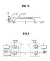
- FIG. 9 The basic structure of such a xDSL system is shown in Fig. 9.
- Reference number 1 in Fig. 9 designates a telephone exchange, which is connected to a transmission path 3 via a first LP (low pass) Filter 2.
- a first xDSL modem 4 is connected on the telephone exchange side to said transmission path 3 via a first HP (high pass) Filter 5.
- Said first LP-Filter 2 and said first HP-Filter 5 form a first splitter filter 6 which is used for separating the telephone or ISDN service from a signal transmitted over said transmission path 3 by said xDSL system.
- Said transmission path 3 can be e.g. a twisted-pair subscriber line.
- EP 0 802 649 A1 suggests a solution for compensating for intersymbol interference caused by transients filtered in the transmission path.
- a prefix and/or suffix and/or symbol extension is inserted in front of each DMT-symbol before transmission of the DMT-symbol over the transmission path.
- the length of this prefix and/or suffix and/or symbol extension equals at least the length of the equalized channel impulse response of the respective transmission path.
- EP 0 725 509 A1 suggests to use a prefix having p-bits (p being an integer) whose values are equal to the values of p-bits at the end of the respective data symbol.
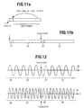
- Fig. 11b shows two successively sent DMT-symbols 20 and 22, respectively having a prefix 21 and 23.
- prefix 21 and 23 In front of each of said prefixes 21 and 23, there are transients filtered in the transmission paths. The cause of these transients will be explained with more detail with reference to figure 12.
- Fig. 12 shows two of the plurality of carriers in a DMT-signal.
- the two carriers 30 and 31 have different frequencies.
- the first carrier 30 has a first frequency f 1 and the second carrier 31 has a second frequency f 2 .
- Reference number 24 relates to a first DMT-symbol on said first carrier 30 with a prefix 25, followed by a second DMT-symbol 26 with a prefix 27.
- the requirements for the HP-Filter at the receiving side become more stringent, implying longer impulse responses for the HP-Filter especially on the receiving side.
- the lengths of the prefixes have to be extended.
- EP 0 929 172 A1 published on July 14, 1999, describes a multicarrier modulation system with variable symbol rates wherein in fallback modes an increased guard cime is provided for a better delay spread tolerance and increased symbol length provides improved signal to noise performance.
- a guard time is interposed between successive ones of the symbols, while the length of the guard time is greater for modes with a greater value of K.
- to replace in the context of the present application is not limited to a complete replacement of the first prefix by the second prefix. That is, the term "to replace” as used in the present application includes to replace only a part of the first prefix by the second prefix and not only the whole first prefix. In other words, ic is possible co replace e.g. only the first or last 10 samples of the first prefix by the second prefix, or to replace a suitable number of samples in the middle of the first prefix.
- a signal is transmitted over a transmission path 30 from a sending side (not shown) to the receiver 31.
- Said signal comprises a plurality of data symbols which are sent over said transmission path 30 one after the other.
- In front of each of said data symbols there is a first prefix. This first prefix is for avoiding an interference between the successively transmitted data symbols occurring due to transients filtered by the transmission path 30.
- the transmission path 30 is connected to a receiver 31 of the receiving side of the transmission system.
- the receiver 31 comprises a buffer 32 for buffering the received signal.
- a means 33 for generating a second prefix is connected to said buffer 32 and to a replacing means 34 for replacing said first prefix sent with each said of said data symbols in said received signal.
- a filter 35 is provided which is connected to said buffer 32 and has its output 36 connected to a decoder (not shown) for decoding the data symbols.
- said filter 35 is a HP (high pass) filter, preferably with sharp slopes.
- step S1 of the flow-chart of Fig. 2 the signal sent from a sending side over the transmission path 30 to the receiver 31 is received.
- the received signal is then buffered or stored in the buffer 32 in step S2.
- said means for generating a second prefix generates a second prefix for each first prefix in front of each of said plurality of data symbols contained in said received signal.
- This second prefix may have an individual length for each of the first prefixes to be replaced, but preferably has a fixed length for all first prefixes to be replaced based on the characteristics such as the impulse response of the filter 35.
- the generation of the second prefix is preferably done by taking a part of the respective data symbol the first prefix of which should be replaced, and to use this part as said second prefix to replace said first prefix.
- This part of the respective data symbol can be the end of the respective data symbol.
- a number of samples from the end of said digital data symbol may be taken as second prefix such that the sample values of said second prefix having a length of n-samples are equal to the values of n-samples at the end of the respective data symbol.
- Said means for generating a second prefix 33 generate said second prefix with a length corresponding to a parameter derived from an impulse response of said filter 35.
- Said second prefix may for example be generated with a length in accordance with a parameter relating to the time needed that transients of said filter 35 have died out to a level having no negative effect for the following data symbol such that an interference of data symbols sent one after another in said signal caused by transients of said filter 35 is avoided.
- Said means for generating a second prefix 33 can also determine the length of said second prefix in correspondence to a parameter relating to the time necessary that the impulse response of said HP-Filter 35 shows a predetermined attenuation, e.g. an attenuation of 40dB and in correspondence with the frequency with which said data symbols are input to said filter 35.
- step S4 the first prefix as sent with the respective data symbol in said signal is replaced by said second prefix generated in said step S3.
- said replacing means 34 instead of replacing said first prefix by said second prefix, said replacing means 34 according to a variant of the first embodiment of the receiver can be adapted to add said second prefix to said first prefix or to insert said second prefix in said first prefix to thereby extend the first prefix.
- the sample values of the second prefix can be used to replace suitable sample values of the first prefix, e.g.
- the first 15 samples of the first prefix, or the sample values of the second prefix can be inserted in said first prefix at sample positions at the beginning, in the middle or at the end of the first prefix.
- the first prefix can be either extended or replaced by a longer second prefix at the receiving side of the transmission system, i.e. in the receiver, without reducing the data transmission rate over the transmission path in spite of using a filter 35 on the receiving side with an impulse response that cannot be compensated for with the length of the first prefix.
- the sent signal wherein the first prefixes in front of the respective data symbols have been replaced by said second prefixes, are filtered by means of said filter 35.
- the filtered signal can then be decoded by means of a decoder (not shown) or further processed in accordance with the modulation scheme used in the transmission system.
- the signal is transmitted over a transmission path, such as a twisted pair subscriber line simultaneously with other services, such as e.g. a telephone service or an ISDN (Integrated Services Digital Network) service.
- a transmission path such as a twisted pair subscriber line simultaneously with other services, such as e.g. a telephone service or an ISDN (Integrated Services Digital Network) service.
- the above signal comprising a plurality of data symbols uses a different frequency band than that used by said telephone or ISDN service.
- the filter 35 used in such a system has a pass characteristic, such that a frequency band of said signal containing the data symbols can pass, but other frequency bands used e.g. by the telephone service or the ISDN service are suppressed.
- said data symbols correspond to DMT-symbols comprising a combined set of modulated carriers, wherein e.g. 2 samples of the data to be transmitted from the sending side to the receiving side of the transmission system, are modulated via 4 QAM (Quadrature Amplitude Modulation) on a first carrier, 8 samples are modulated e.g. via 256 QAM on a second carrier and so on such as described in the above referenced EP 0 802 649 A1.
- QAM Quadrature Amplitude Modulation
- Fig. 3 shows a second embodiment of the receiver for a high speed transmission system according to the present invention.
- the receiver according to the second embodiment of the present invention comprises a first switching means 40 for connecting a first buffer 41 or a second buffer 42 to the transmission path 30.
- the first buffer 41 and the second buffer 42 are respectively connected to means for generating a second prefix 33 and replacing means 34 for replacing said first prefix by said second prefix, which are similar to the first embodiment described with reference to Fig. 1.
- the first buffer 41 can be connected to a decoder (not shown) via a first HP Filter 43 (HP 0 in Fig. 3) by means of a second switching means 45.
- Said second buffer 42 can also be connected to said decoder (not shown) via a second HP Filter 44 (HP 1) by means of said second switching means 45.
- the first line in Fig. 4 shows the received signal, which was sent over the transmission path 30 and input to the receiver.
- the received signal shown in the first line of Fig. 4 comprises three data symbols, namely symbol 0, symbol 1 and symbol 2, indicated with reference numbers 50a, 51a and 52a, respectively.
- a respective first prefix cp In front of each of said data symbols 50a, 51a and 52a there is a respective first prefix cp, respectively indicated with reference numbers 50b, 51b, 52b.
- transients are caused at the beginning of each of said first prefixes 50b, 51b and 52b in said transmission path.
- the first prefixes 50b, 51b and 52b are sufficiently long for ensuring that transients of said transmission path 30 have already died out before said symbols 50a, 51a and 52a are transmitted and that there is no intersymbol interference caused in said transmission path 30.
- Reference number 53 indicate small amplitude-time diagrams representing the impulse response of said first and second HP-Filters 43 and 44 (HP 0 and HP 1) for showing a dimensional comparison of the length of the first prefixes 50b, 51b and 52b, as contained in said signal transmitted over said transmission path 30 to the impulse response of the first and second HP-filters 43 and 44.
- Said first switching means 40 switches said transmission path to said first buffer 41 and to said second buffer 42 alternately, such that successively transmitted data symbols 50a, 51a and 52a are alternately stored in said first buffer 41 and said second buffer 42.
- the data symbol indicated with reference number 50a in Fig. 4 is stored in said first buffer 41 together with the respective first prefix 50b.
- said switching means 40 is switched to said second buffer 42, and the following symbol, namely the symbol indicated with reference number 51a in Fig. 4, is stored in said second buffer 42 together with the respective first prefix 51b.
- said first switching means 40 is switched back to said first buffer 41 and the successively received data symbol, namely data symbol 52a in Fig. 4, is stored in said first buffer 41 together with the respective first prefix 52b.
- said means 33 for generating a second prefix generates a second prefix 54, 55 in the same manner as described with reference to Fig. 1 for of said first prefixes 50b, 51b and 52b stored in the first and the second buffer 41 and 42.
- the replacing means 34 replaces said first prefixes 50b, 51b and 52b in the first and second buffer 41 and 42 by said second prefix 54, 55. It has to be noted, that, as described with reference to Fig. 1, said replacing means 34 can also be adapted to extend said first prefix 50b, 51b and 52b by inserting said second prefix 54, 55 into said first prefix 50b, 51b and 52b or to add said second prefix 54, 55 to the respective first prefix 50b, 51b and 52b.
- the data symbol 50a is input to the first HP-Filter 43 with a second (or extended) prefix 54 (ECP) in front.
- the first prefix 50b has been replaced by said second prefix 54.
- the term "replace” is to be understood broadly as relating to a suitable change in the prefix. The term does not imply that the first prefix has to be removed completely or the like, because the replacement can simply consist in an extension of the first prefix as indicated above. Naturally, it is also possible that the first prefix is removed completely before a new prefix is added.
- the second prefix 54 is long enough to ensure that the transient of the HP filter HP 0 has died out before the data symbol 50a is inserted to the HP filter HP 0.
- the second symbol 1 carrying the reference number 51a is input to the second HP-Filter HP 1 carrying the reference number 44.
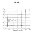
- Fig. 5a shows an example of an HP-Filter, which can be used as HP-Filters HP 0 and 1 in Fig. 3 (reference numbers 43 and 44) or as Filter 35 in Fig. 1.
- this HP-Filter is of a low order.
- HP-Filters having a higher order can be used in order to better adapt the filter characteristics to the transmission path.
- the high pass filter shown in Fig. 5a comprises a first filter portion constituted by an FIR-Filter 60 and a second filter portion constituted by an IIR-Filter 61.
- the FIR-Filter 60 and the IIR-Filter 61 are connected in series with each other.
- the input of the FIR filter 60 is connected to a first one-sample delay element 62.
- the output of said first one-sample delay element 62 is connected to the input of a second one-sample delay element 63.
- the input of the FIR filter 60 is further multiplied by a coefficient a 0 by means of a first multiplier 64 and added to the output of the first one-sample delay element 62, which has been multiplied with a coefficient a 1 by means of a second multiplier 65, by means of a first adder 66.
- the output of the first adder 66 is added to the output of the second one-sample delay element 63, which has been multiplied with a coefficient a 2 by a third multiplier 67 by means of a second adder 68.
- the first and second one-sample delay elements 62 and 63, the first, second and third multipliers 64, 65 and 67 and the first and second adders 66 and 68 constitute the FIR-Filter 60.
- the output of the FIR-Filter 60 namely the output of the adder 68 is input to a third adder 69, whose output is the output of the IIR-Filter 61 and whose output is input to a third one-sample delay element 70.
- the output of the third one-sample delay element is input to a fourth one-sample delay element 71.
- the output of the third one-sample delay element 70 and the fourth one-sample delay element 71 are respectively multiplied with coefficients a 3 and a 4 by means of a fourth multiplier 72 and a fifth multiplier 73, and then added by means of a fourth adder 74.
- the output of the fourth adder 74 is then added to the output of FIR-Filter 60 by means of said third adder 69.
- the third and fourth one-sample delay elements 70 and 71, the fourth and fifth multipliers 72 and 73 and the third and fourth adder 69 and 74 constitute said IIR-Filter 61.
- the total impulse response is longer than each of the individual impulse responses of the FIR- and the IIR- Filter as indicated with the above equations.
- Fig. 5b shows the frequency response of the FIR-Filter 60
- Fig. 5c shows the frequency response of the IIR-Filter 61
- the total frequency response of the HP filter shown in Fig. 5a is shown in Fig. 5d.
- the FIR-Filter 60 is a nonrecursive filter, which introduces zeros in the transfer function of the HP filter shown in Fig 5a and attenuates the low frequencies.
- the impulse response thereof is finite.
- the IIR-Filter 61 is recursive and introduces poles in the transfer function of the HP filter shown in Fig 5a and compensates in this arrangement for the frequency response of the FIR-Filter 60, and flattens the frequency response in the pass band.
- the impulse response of the IIR-Filter 61 is infinite.
- the FIR-Filter 60 and IIR-Filter 61 can be separated.
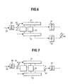
- Fig. 6 shows the third embodiment of the receiver according to the present invention, using a HP filter comprising a recursive and a nonrecursive filter portion, such as the one described with reference to figs. 5a - 5d.
- Fig. 6 shows a third embodiment of the receiver according to the present invention which has a similar arrangement as the receiver according to the second embodiment described with reference to Fig. 3, except that the HP filters HP 0 and HP 1, indicated with reference numbers 43 and 44 in Fig. 3, are replaced by a HP filter having two filter portions, namely a recursive filter portion and a nonrecursive filter portion.
- This HP filter is constituted depending on the switching state of the first switching means 40 by a first filter portion HP FIR, indicated with reference number 80, which is arranged in front of said replacing means 34 with respect to the transmission path, and one of second filter portions HP IIR 0 and HP IIR 1, indicated with reference numbers 81 and 82 which are arranged behind said replacing means 34.
- the first filter portion 80 (HP FIR) is arranged in front of said first switching means 40 and connected to said transmission path 30.
- said first filter portion 80 (HP FIR) is used for both of said second filter portions 81 and 82 (HP IIR 0, HP IIR 1) for respectively forming a HP filter having a pass characteristic, such that the signal comprising said plurality of data symbols with a prefix in front of each can pass.
- Said first filter portion 80 (HP FIR) is a nonrecursive filter such as the one indicated with reference number 60 in Fig. 5a and has a finite impulse response.
- Said second filter portions 81 and 82 (HP IIR 0 and HP IIR 1) are recursive filters such as the one indicated with reference number 61 in Fig. 5a and respectively have an infinite impulse response.
- the first filter portion 80 filters non-periodic low frequency disturbances from the signal received over the transmission path 30.
- Said second filter portions 81 and 82 respectively compensate for the frequency response of the first filter portion 80 (HP FIR) and respectively flatten the frequency response of the whole HP filter (constituted by HP FIR and HP IIR 0 or HP FIR and HP IIR 1, respectively) in the pass band.
- Fig. 7 shows a fourth embodiment of the receiver according to the present invention.
- the receiver according to the fourth embodiment of the present invention is similar to the receiver according to the third embodiment of the present invention, described with reference to Fig. 6, except that said second switching means 45 is arranged between the outputs of said first buffer 41 and said second buffer 42 for alternately switching said outputs to a second filter portion 83 (HP IIR).
- the output of the second filter portion 83 is connected to a decoder (not shown) formed in accordance with the respective modulation scheme.
- Said second switching means 45 are arranged to alternately connect said first and said second buffers 41 and 42 to said second filter portion 83 (HP IIR). Due to this arrangement, only one second filter portion 83 (HP IIR) has to be arranged allowing to reduce the complexity of the receiver and to reduce the manufacturing costs thereof.
- said first switching means 40 and said second switching means 45 switch with a certain frequency which is synchronized with the frequency of said data symbols in said received signal, if said data signals contained in said received signal are periodic.
- said switching means are controlled by means of a data symbol detecting means (not shown). This data symbol detecting means detects the data symbols or the first prefixes in front of said data symbols in said received signal and controls the switching of said first and second switching means 40 and 35 such that the switching is performed alternately after each data symbol.
- Fig. 8 shows an embodiment of a modem according to the present invention.
- This modem is for sending and receiving a signal over a transmission path 30.
- the sent or received signal comprises a plurality of data symbols which are successively transmitted.
- In front of each of said data symbols is a first prefix for avoiding an interference between successive data symbols caused by transients of said transmission path 30.
- This signal preferably uses a first frequency band which is different from a second frequency band used by other signals transmitted simultaneously over said transmission path 30.
- said signal is transmitted in a frequency band starting from 300kHz up to 10 MHz, and other signals are telephone or ISDN services which are transmitted in a frequency band ranging from 0 to 3 kHz (POTS) or 0 to 160 kHz (ISDN).
- POTS 3 kHz
- ISDN 160 kHz
- the modem is a DMT xDSL modem.
- the present invention can also be applied to other transmission systems wherein a signal comprising successively transmitted data signals is sent over a transmission path.
- Reference number 90 in Fig. 8 designates an IFFT (Inverse Fast Fourier Transformation) transformation means which converts a set of modulated carriers from an encoder from frequency domain to time domain. This combined set of modulated carriers is a data symbol and is called, in case of a DMT xDSL modem, a DMT-symbol.
- a first prefix adder 91 is provided for adding a first prefix to each of said data symbols with a length corresponding to the impulse response of the transmission path 30 for avoiding an interference between successively transmitted data symbols caused by transients of said transmission path 30.
- a parallel-to-serial converter 92 connected to the output of said prefix adder 90 generates a serial data stream by serializing successive data symbols.
- the serialized data symbols are then transformed into an analogue signal by a digital-to-analogue converter 93 connected to an output of said parallel-to-serial converter 92.
- the thereby generated signal is then applied to the transmission path 30 via switching means 94.
- a digital HP-Filter (not shown) can be provided between said parallel-to-serial converter 92 and said digital-to-analogue converter 93, and an analogue HP-Filter can optionally be provided between said digital-to-analogue converter 93 and said switching means 94 for removing disturbances from the signal applied to said transmission path 30.
- Said switching means 94 connects the sending branch of the modem comprising said IFFT transformation means 90, said prefix adder 91, said parallel-to-serial converter 92 and said digital-to-analogue converter 93 to the transmission path 30 if a signal is to be sent from the encoder to said transmission path 30 and connects the transmission path 30 to a receiving branch of said modem, which will be described in the following under the assumption that a signal is sent from a sending side (not shown) to the modem.
- said switching means 94 is connecting said transmission path 30 to the receiving branch of the modem.
- Said received analogue signal is firstly digitized in an analogue-to-digital converter 95, and then input to a time domain equalizer 96, which digitally filters the received data symbols to compensate for intersymbol interference on the transmission path 30.
- a first HP filter 97 is connected to the output of the time domain equalizer 96 for removing low frequency disturbances which are not periodic compared to the data symbol length from the received signal.
- This first HP filter 97 is preferably a nonrecursive HP filter having a finite impulse response.
- This first HP filter 97 forms a HP filter system together with a second HP filter 101, which is a recursive filter having an infinite impulse response.
- the nonrecursive HP filter 97 introduces zeros in the transfer function of the HP filter system and attenuates the low frequencies.
- the recursive HP filter 101 introduces poles into the transfer function of the HP filter system and compensates for the frequency response of the first HP filter 97.
- the FIR-Filter 60 described with reference to Fig. 5a is used as first HP filter 97 and the IIR-Filter 61 described with reference to Fig. 5a as said second HP filter 101.
- the output of the first HP filter 97 is input to buffer means 98 for buffering the received signal.
- means for generating a second prefix 99 are generating a second prefix having a length longer than that of the respective first prefix in front of each of said data symbols.
- Said second prefix is preferably generated with a length corresponding to a parameter derived from the impulse response of the filter system constituted by said first HP filter 97 and said second HP filter 101, such that an interference of successive ones of said plurality of data symbols of the received signal caused by transients of said filter system is avoided.
- This parameter may relate - as already indicated with reference to the first embodiment - to the time until the amplitude of the impulse response of the filter system is reduced to a certain threshold, or shows an attenuation of e.g. 40dB, after a Dirac impulse was input to the filter system.
- This parameter may also relate to a time (or time period) after the input of a data symbol after that the transients caused by the data symbol have no adverse effect on the successively input data symbol.
- Replacing means 100 for replacing said first prefix by said second prefix generated in said means 99 for generating a second prefix respectively replace the first prefixes in front of said data symbols by said second prefix.
- the output of said replacing means 100 is input to said second HP filter 101.
- the output of the second HP filter 101 is input to a serial-to-parallel converter 102, which can further be adapted to remove the respective second prefix from the data symbols.
- the output of said serial-to-parallel converter 102 is then input to a FFT (Fast Fourier Transformation) transformation means 103, which converts the data symbols from the time domain to frequency domain which are then output to a suitable decoder.
- FFT Fast Fourier Transformation
- the receiving branch of said modem may further comprise an analogue high pass filter (not shown) which is arranged between said switching means 94 and said analogue-to-digital converter 95 for removing disturbances from the received signal.
- analogue high pass filter (not shown) which is arranged between said switching means 94 and said analogue-to-digital converter 95 for removing disturbances from the received signal.
- said filter system constituted by said first HP filter 97 and said second HP filter 101 is replaced by a single filter, e.g. of the kind of filter 35 described with reference to Figs. 1 and 2 which is arranged behind said replacing means 100.
- said buffer means 98 comprises a first buffer portion and a second buffer portion similar to the first buffer 41 and the second buffer 42 described with reference to Figs. 3, 4, 6 and 7 and said modem further comprises a first buffer switching means similar to the first switching means 40 described with reference to Figs. 3, 4, 6 and 7.
- the modem further comprises second buffer switching means similar to the second switching means 45 described with reference to Figs. 3,4,6 and 7, either arranged in front of the second HP filter 101 similar to the arrangement shown in Fig. 7, or behind two of said second HP filters 101 similar to the arrangement shown in Fig. 6 or behind two high pass filters such as the HP filters HP 0 and HP 1 described with reference to Fig. 3 if instead of said first HP filter 97 and said second HP filter 101, one part filters such as the HP filters HP 0 and HP 1 are used, similar to the arrangement shown in Fig. 3.
Landscapes
- Engineering & Computer Science (AREA)
- Computer Networks & Wireless Communication (AREA)
- Signal Processing (AREA)
- Cable Transmission Systems, Equalization Of Radio And Reduction Of Echo (AREA)
- Dc Digital Transmission (AREA)
- Telephonic Communication Services (AREA)
- Reduction Or Emphasis Of Bandwidth Of Signals (AREA)
Claims (11)
- Ein Empfänger für ein Hochgeschwindigkeitsübermittlungssystem zum Empfangen eines ersten Signals (B) über einen Übermittlungspfad (30), wobei das erste Signal (B) eine Mehrzahl von aufeinanderfolgend übermittelten Datensymbolen (50a, 51a, 52a) umfasst, wobei sich vor jedem ein erstes Präfix (50b, 51b, 52b) zum Vermeiden einer Interferenz zwischen den aufeinanderfolgend übermittelten Datensymbolen (50a, 51a, 52a) befindet, wobei der Empfänger umfasst:gekennzeichnet durchEinrichtung (33) zum Erzeugen eines zweiten Präfixes (53, 55) für jedes erste Präfix (50b, 51b, 52b) vor jedem der Mehrzahl von Datensymbolen (50a, 51a, 52a); undErsetzungseinrichtung (34) zum Ersetzen des ersten Präfixes (50b, 51b, 52b) durch das zweite Präfix (53, 55), wobei das zweite Präfix (53, 55) jeweils eine Länge aufweist, die länger als das zu ersetzende erste Präfix (50b, 51b, 52b) ist,einen Puffer (32) zum Puffern des ersten Signals;einen Filter (35), der eine Durchlasscharakteristik derart aufweist, dass das erste Signal passieren kann, mit einem ersten Filterteil (60), der eine finite Impulsantwort aufweist, die Nullen in die Übertragungsfunktion des Filters (35) einfügt, und einen zweiten Filterteil (61), der eine infinite Impulsantwort aufweist, die Pole in die Übertragungsfunktion des Filters (35) einfügt;wobei der erste Filterteil (60) vor der Ersetzungseinrichtung (34) in Bezug auf den Übermittlungspfad (30), und der zweite Filterteil (61) hinter diesem angeordnet ist.
- Ein Empfänger gemäß Anspruch 1, gekennzeichnet durch Empfangen eines zweiten Signals (A) über den Übermittlungspfad (30) gleichzeitig mit dem ersten Signal (B), wobei das erste und das zweite Signal verschiedene Frequenzbänder aufweisen und die Durchlasscharakteristik des Filters derart ist, dass das zweite Signal (A) den Filter (35) nicht passieren kann.
- Ein Empfänger gemäß Anspruch 1 oder 2, dadurch gekennzeichnet, dass für ein gegebenes Datensymbol (50a, 51a, 52a) das zweite Präfix (53, 55) ein Teil des gegebenen Datensymbols ist.
- Ein Empfänger gemäß Anspruch 1, 2 oder 3, dadurch gekennzeichnet, dassder Puffer (32) einen ersten Pufferteil (41) und einen zweiten Pufferteil (42) umfasst;ein Schaltmittel (40) bereitgestellt ist zum Schalten des Übermittlungspfads (30) auf den ersten und zweiten Pufferteil (41, 42) derart, dass aufeinanderfolgend übermittelte von der Mehrzahl von Datensymbolen (50a, 51a, 52a) abwechselnd in dem ersten und zweiten Pufferteil (41, 42) gepuffert werden.
- Ein Empfänger gemäß einem der Ansprüche 1 bis 4, dadurch gekennzeichnet, dass die Einrichtung (33) zum Erzeugen eines zweiten Präfixes das zweite Präfix (53, 55) mit einer Länge entsprechend einem Parameter erzeugt, der von einer Impulsantwort des Filters (35) abgeleitet ist, derart, dass eine durch Transiente des Filters (35) verursachte Interferenz von aufeinanderfolgenden der Mehrzahl von Datensymbolen (50a, 51a, 52a) des ersten Signals (B) vermieden wird.
- Ein Empfänger gemäß einem der vorherigen Ansprüche, dadurch gekennzeichnet, dass der Übermittlungspfad (30) eine Telefonleitung ist und das zweite Signal ein Telefondienst oder ISDN-Dienst ist.
- Ein Modem, das einen Empfänger gemäß einem der Ansprüche 1 bis 6 einschließt.
- Ein Verfahren zum Empfangen eines Signals (B) auf der Empfangsseite eines Übermittlungssystems, wobei das Signal Datensymbole (50a, 51a, 52a) und ein erstes Präfix (50b, 51b, 52b) vor jedem Datensymbol (50a, 51a, 52a) zum Vermeiden einer Interferenz von aufeinanderfolgend übermittelten Datensymbolen (50a, 51a, 52a) umfasst, die folgenden Schritte umfassend:Empfangen des Signals auf der Empfangsseite (S1);Puffern des empfangenen Signals (S2);Erzeugen eines zweiten Präfixes für jedes erste Präfix vor jedem der Datensymbole (S3);Ersetzen des ersten Präfixes durch das zweite Präfix, wobei das zweite Präfix eine Länge aufweist, die länger ist als die des zu ersetzenden ersten Präfixes (S4);Filtern des Signals, wobei das erste Präfix durch das zweite Präfix mittels eines Filters ersetzt wurde, der eine Durchlasscharakteristik derart aufweist, dass das Signal passieren kann (S5), einschließlich erstes Filtern des Signals mit einem ersten Filterteil (60), der eine finite Impulsantwort (FIR) aufweist, die Nullen in die Übertragungsfunktion des Filters (35) vor dem Ersetzen des ersten Präfix (50b, 51b, 52b) einfügt, und zweites Filtern des Signals (B), wobei die ersten Präfixes (50b, 51b, 52b) durch die zweiten Präfixes (50a, 51a, 52a) mittels eines zweiten Filterteils (61) ersetzt worden sind, der eine infinite Impulsantwort (IIR) aufweist, die Pole in die Übertragungsfunktion des Filters (35) einfügt.
- Ein Verfahren gemäß Anspruch 8, dadurch gekennzeichnet, dass für ein gegebenes Datensymbol (50a, 51a, 52a) das zweite Präfix (53, 55) durch Verwenden eines Teils des gegebenen Datensymbols erzeugt wird.
- Ein Verfahren gemäß Anspruch 8 oder 9, dadurch gekennzeichnet, dass das Puffern des empfangenen Signals (B) durch Schalten des Übermittlungspfads (30) auf einen ersten und einen zweiten Pufferteil (40, 41) derart durchgeführt wird, dass aufeinanderfolgend empfangene Datensymbole (50a, 51a, 52a) abwechselnd in dem ersten und zweiten Pufferteil (40, 41) gespeichert werden.
- Ein Verfahren gemäß einem der Ansprüche 8 bis 10, dadurch gekennzeichnet, dass das zweite Präfix (53, 55) mit einer Länge entsprechend einem Parameter erzeugt wird, der von einer Impulsantwort des Filters (35) derart abgeleitet wird, dass eine durch Transiente des Filters (35) verursachte Interferenz von aufeinanderfolgenden Datensymbolen (50a, 51a, 52a) des Signals (B) vermieden wird.
Applications Claiming Priority (3)
| Application Number | Priority Date | Filing Date | Title |
|---|---|---|---|
| DE19858106.8A DE19858106B4 (de) | 1998-12-16 | 1998-12-16 | Empfänger und Verfahren zum Verhindern einer Zwischensymbolstörung in einem Hochgeschwindigkeitsübertragungssystem |
| DE19858106 | 1998-12-16 | ||
| PCT/EP1999/009197 WO2000036801A1 (en) | 1998-12-16 | 1999-11-26 | Receiver and method for avoiding intersymbol interference in a high speed transmission system |
Publications (2)
| Publication Number | Publication Date |
|---|---|
| EP1142246A1 EP1142246A1 (de) | 2001-10-10 |
| EP1142246B1 true EP1142246B1 (de) | 2005-01-19 |
Family
ID=7891324
Family Applications (1)
| Application Number | Title | Priority Date | Filing Date |
|---|---|---|---|
| EP99959350A Expired - Lifetime EP1142246B1 (de) | 1998-12-16 | 1999-11-26 | Empfänger und verfahren zur vermeidung von intersymbolstörung in einem hochgeschwindigkeitsübertragungssystem |
Country Status (7)
| Country | Link |
|---|---|
| US (1) | US6870893B2 (de) |
| EP (1) | EP1142246B1 (de) |
| CN (1) | CN1218546C (de) |
| AT (1) | ATE287607T1 (de) |
| AU (1) | AU1655800A (de) |
| DE (1) | DE19858106B4 (de) |
| WO (1) | WO2000036801A1 (de) |
Families Citing this family (20)
| Publication number | Priority date | Publication date | Assignee | Title |
|---|---|---|---|---|
| JP3187024B2 (ja) * | 1999-02-24 | 2001-07-11 | 三菱電機株式会社 | 通信装置および該通信装置における干渉除去方法 |
| US6804313B2 (en) * | 1999-12-30 | 2004-10-12 | Bandspeed, Inc. | Approach for processing data received from a communications channel |
| FR2804560B1 (fr) * | 2000-01-31 | 2006-08-04 | Commissariat Energie Atomique | Procede de radiocommunications amrc avec codes d'acces et recepteur correspondant |
| US6693984B1 (en) | 2000-08-29 | 2004-02-17 | Telefonaktiebolaget Lm Ericsson (Publ) | Method and apparatus for compensating for intersymbol interference in a received signal |
| EP1185047A1 (de) * | 2000-08-29 | 2002-03-06 | Telefonaktiebolaget Lm Ericsson | Schätzung sowie Beseitigung von Intersymbolinterferenz in Mehrträgersignalen |
| DE10129331B4 (de) | 2001-06-19 | 2016-03-10 | Lantiq Deutschland Gmbh | Verfahren und Schaltungsanordnung für Datenstromsender bei diskreten Mehrfachtonsystemen |
| JP3798656B2 (ja) * | 2001-06-22 | 2006-07-19 | 株式会社ケンウッド | 直交周波数分割多重信号受信装置、受信装置、直交周波数分割多重信号受信方法及び受信方法 |
| US7388930B1 (en) | 2001-08-10 | 2008-06-17 | Bandspeed, Inc. | Method and apparatus for removing crosstalk and other interference in communications systems |
| US7113559B2 (en) * | 2001-09-24 | 2006-09-26 | Atheros Communications, Inc. | Efficient methods for filtering to avoid inter-symbol interference and processing digital signals having large frequency guard bands |
| KR100447242B1 (ko) * | 2002-01-31 | 2004-09-04 | 주식회사 휴커넥스 | Dmt 방식의 vdsl 시스템 및 이 시스템에서의 주기적 프리픽스 샘플 길이 결정 방법 |
| KR100453766B1 (ko) * | 2002-01-31 | 2004-10-20 | 주식회사 휴커넥스 | 디엠티 시스템 및 이 시스템에서의 타이밍 어드밴스 결정 방법 |
| EP1518378A2 (de) | 2002-06-14 | 2005-03-30 | GlobeSpan Virata Incorporated | Vorrichtung und verfahren zum anbringen eines übertragungsfenster in adsl-netzwerken |
| JP4298320B2 (ja) | 2002-11-08 | 2009-07-15 | 富士通株式会社 | Ofdm伝送方式における受信装置 |
| DE10256452A1 (de) * | 2002-12-03 | 2004-06-24 | Rohde & Schwarz Gmbh & Co. Kg | Verfahren zur Analyse der Kanalimpulsantwort eines Übertragungskanals |
| DE10354113B4 (de) * | 2003-11-19 | 2006-07-27 | Infineon Technologies Ag | Übertragungsvorrichtung mit variabler Impedanzanpassung |
| US20050276337A1 (en) * | 2004-06-09 | 2005-12-15 | Lucent Technologies, Inc. | Bandwidth efficient orthogonal frequency division multiplexing communication system |
| US7787481B1 (en) * | 2004-07-19 | 2010-08-31 | Advanced Micro Devices, Inc. | Prefetch scheme to minimize interpacket gap |
| US7622666B2 (en) * | 2005-06-16 | 2009-11-24 | Soliant Energy Inc. | Photovoltaic concentrator modules and systems having a heat dissipating element located within a volume in which light rays converge from an optical concentrating element towards a photovoltaic receiver |
| JP2007206799A (ja) * | 2006-01-31 | 2007-08-16 | Toshiba Corp | データ転送装置、情報記録再生装置およびデータ転送方法 |
| US8300518B2 (en) * | 2008-04-01 | 2012-10-30 | Alcatel Lucent | Fast seamless joining of channels in a multi-channel communication system |
Family Cites Families (19)
| Publication number | Priority date | Publication date | Assignee | Title |
|---|---|---|---|---|
| DE4319217C2 (de) * | 1993-06-10 | 1995-02-09 | Hermann Prof Dr Rohling | Verfahren zum Senden und/oder Empfangen hoher digitaler Datenmengen in paralleler Form und zur Durchführung des Verfahrens geeignete Sender und Empfänger |
| FI96372C (fi) | 1994-06-16 | 1996-06-10 | Nokia Technology Gmbh | Kehystahdistus digitaalisia radiolähetyksiä vastaanottavassa laitteessa |
| DE4425713C1 (de) | 1994-07-20 | 1995-04-20 | Inst Rundfunktechnik Gmbh | Verfahren zur Vielträger Modulation und Demodulation von digital codierten Daten |
| US5682376A (en) * | 1994-12-20 | 1997-10-28 | Matsushita Electric Industrial Co., Ltd. | Method of transmitting orthogonal frequency division multiplex signal, and transmitter and receiver employed therefor |
| EP0725509A1 (de) * | 1995-01-31 | 1996-08-07 | ALCATEL BELL Naamloze Vennootschap | Speziell zugeordnetes Übertragungssystem mit Frequenzmultiplex mit Mehrfachzugriff (FDMA), Sender und Empfänger in einem solchen Übertragungssystem |
| JP3130752B2 (ja) | 1995-02-24 | 2001-01-31 | 株式会社東芝 | Ofdm伝送受信方式及び送受信装置 |
| EP0740437A1 (de) | 1995-04-28 | 1996-10-30 | Koninklijke Philips Electronics N.V. | Hardware-effiziente Frequenzentschachtelung |
| JP2802255B2 (ja) * | 1995-09-06 | 1998-09-24 | 株式会社次世代デジタルテレビジョン放送システム研究所 | 直交周波数分割多重伝送方式及びそれを用いる送信装置と受信装置 |
| SE9600537L (sv) * | 1996-02-14 | 1997-05-26 | Telia Ab | Förfarande och anordning i ett OFDM system med variabel varaktighet av symbolskur |
| EP0802649A1 (de) * | 1996-04-19 | 1997-10-22 | ALCATEL BELL Naamloze Vennootschap | Verfahren und Fensteranordnung zum Reduzieren von Verlusten, Fourier-Transformation und DMT-Modem wobei diese Anordnung verwendet wird |
| US6055268A (en) * | 1996-05-09 | 2000-04-25 | Texas Instruments Incorporated | Multimode digital modem |
| DE19618561A1 (de) * | 1996-05-09 | 1997-11-13 | Iaf Inst Fuer Angewandte Funks | Verfahren und Vorrichtung zum Verarbeiten eines Multiträger-Empfangssignals |
| DE19620042A1 (de) * | 1996-05-17 | 1997-11-20 | Siemens Ag | Verfahren zur hochratigen digitalen Signalübertragung |
| FI102231B1 (fi) * | 1996-09-16 | 1998-10-30 | Nokia Technology Gmbh | Symbolitahdistuksen ja näytteenottotaajuuden säätömenetelmä OFDM-moduloituja lähetyksiä vastaanottavassa laitteessa sekä menetelmän toteuttava laite |
| EP2154854B1 (de) * | 1998-01-06 | 2012-03-07 | Mosaid Technologies Incorporated | System zur Mehrträgermodulation mit veränderbaren Symbolgeschwindigkeiten |
| US6226322B1 (en) * | 1998-03-30 | 2001-05-01 | Texas Instruments Incorporated | Analog receive equalizer for digital-subscriber-line communications system |
| US6526105B1 (en) * | 1998-05-29 | 2003-02-25 | Tellabs, Operations, Inc. | Time domain equalization for discrete multi-tone systems |
| US6266367B1 (en) * | 1998-05-28 | 2001-07-24 | 3Com Corporation | Combined echo canceller and time domain equalizer |
| US6426972B1 (en) * | 1998-06-19 | 2002-07-30 | Nxtwave Communications | Reduced complexity equalizer for multi mode signaling |
-
1998
- 1998-12-16 DE DE19858106.8A patent/DE19858106B4/de not_active Expired - Fee Related
-
1999
- 1999-11-26 EP EP99959350A patent/EP1142246B1/de not_active Expired - Lifetime
- 1999-11-26 WO PCT/EP1999/009197 patent/WO2000036801A1/en not_active Ceased
- 1999-11-26 CN CN998162205A patent/CN1218546C/zh not_active Expired - Fee Related
- 1999-11-26 AU AU16558/00A patent/AU1655800A/en not_active Abandoned
- 1999-11-26 AT AT99959350T patent/ATE287607T1/de not_active IP Right Cessation
-
2001
- 2001-06-15 US US09/881,057 patent/US6870893B2/en not_active Expired - Lifetime
Also Published As
| Publication number | Publication date |
|---|---|
| US6870893B2 (en) | 2005-03-22 |
| WO2000036801A1 (en) | 2000-06-22 |
| CN1335011A (zh) | 2002-02-06 |
| DE19858106A1 (de) | 2000-06-29 |
| ATE287607T1 (de) | 2005-02-15 |
| AU1655800A (en) | 2000-07-03 |
| CN1218546C (zh) | 2005-09-07 |
| DE19858106B4 (de) | 2014-09-25 |
| US20020001355A1 (en) | 2002-01-03 |
| EP1142246A1 (de) | 2001-10-10 |
Similar Documents
| Publication | Publication Date | Title |
|---|---|---|
| EP1142246B1 (de) | Empfänger und verfahren zur vermeidung von intersymbolstörung in einem hochgeschwindigkeitsübertragungssystem | |
| CA2258412C (en) | Reduction of interference in discrete multi-tone (dmt) based communications systems | |
| Faulkner | The effect of filtering on the performance of OFDM systems | |
| US6693984B1 (en) | Method and apparatus for compensating for intersymbol interference in a received signal | |
| US9806925B2 (en) | Frequency division multiplexing system with selectable rate | |
| JP3191767B2 (ja) | ディジタル通信装置 | |
| US7200196B2 (en) | Interpolation based timing recovery | |
| US6763061B1 (en) | Frequency domain technique for narrowband noise cancellation in DMT receivers | |
| US6665349B1 (en) | Filtered multitone transmission application to DSL technologies | |
| EP1062760B1 (de) | Verbesserungen bei vdsl | |
| JP2001148643A (ja) | ウィンドウ制御離散マルチトーン形モデム受信機におけるビン(bin)毎に適応する等化処理 | |
| EP1232600B1 (de) | Mehrträger nachrichtenübertragungssystem und verfahren | |
| US20010036225A1 (en) | Coefficient update method and receive method of time domain equalizer of DMT system, DMT system and DMT modem | |
| US6781965B1 (en) | Method and apparatus for echo cancellation updates in a multicarrier transceiver system | |
| JP3502607B2 (ja) | 離散型マルチトーン変調により生成した信号のためのデジタル受信機 | |
| US20060133467A1 (en) | Method and apparatus for generating a periodic training signal | |
| EP1185047A1 (de) | Schätzung sowie Beseitigung von Intersymbolinterferenz in Mehrträgersignalen | |
| EP1303093B1 (de) | Verkürzung der Impulsantwort in DMT-Modems | |
| Matheus et al. | Implementation of multicarrier systems with polyphase filterbanks | |
| JP2001053653A (ja) | エコーキャンセラ | |
| EP1434363A1 (de) | Effiziente Echounterdrücksvorrichtung und Verfahren |
Legal Events
| Date | Code | Title | Description |
|---|---|---|---|
| PUAI | Public reference made under article 153(3) epc to a published international application that has entered the european phase |
Free format text: ORIGINAL CODE: 0009012 |
|
| 17P | Request for examination filed |
Effective date: 20010704 |
|
| AK | Designated contracting states |
Kind code of ref document: A1 Designated state(s): AT BE CH CY DE DK ES FI FR GB GR IE IT LI LU MC NL PT SE |
|
| AX | Request for extension of the european patent |
Free format text: AL;LT;LV;MK;RO;SI |
|
| RAP1 | Party data changed (applicant data changed or rights of an application transferred) |
Owner name: TELEFONAKTIEBOLAGET LM ERICSSON (PUBL) |
|
| RBV | Designated contracting states (corrected) |
Designated state(s): AT DK FR |
|
| REG | Reference to a national code |
Ref country code: DE Ref legal event code: 8566 |
|
| GRAP | Despatch of communication of intention to grant a patent |
Free format text: ORIGINAL CODE: EPIDOSNIGR1 |
|
| GRAS | Grant fee paid |
Free format text: ORIGINAL CODE: EPIDOSNIGR3 |
|
| GRAA | (expected) grant |
Free format text: ORIGINAL CODE: 0009210 |
|
| AK | Designated contracting states |
Kind code of ref document: B1 Designated state(s): AT DK FR |
|
| PG25 | Lapsed in a contracting state [announced via postgrant information from national office to epo] |
Ref country code: AT Free format text: LAPSE BECAUSE OF FAILURE TO SUBMIT A TRANSLATION OF THE DESCRIPTION OR TO PAY THE FEE WITHIN THE PRESCRIBED TIME-LIMIT Effective date: 20050119 |
|
| REG | Reference to a national code |
Ref country code: IE Ref legal event code: FG4D |
|
| PG25 | Lapsed in a contracting state [announced via postgrant information from national office to epo] |
Ref country code: DK Free format text: LAPSE BECAUSE OF FAILURE TO SUBMIT A TRANSLATION OF THE DESCRIPTION OR TO PAY THE FEE WITHIN THE PRESCRIBED TIME-LIMIT Effective date: 20050419 |
|
| PLBE | No opposition filed within time limit |
Free format text: ORIGINAL CODE: 0009261 |
|
| STAA | Information on the status of an ep patent application or granted ep patent |
Free format text: STATUS: NO OPPOSITION FILED WITHIN TIME LIMIT |
|
| ET | Fr: translation filed | ||
| 26N | No opposition filed |
Effective date: 20051020 |
|
| PGFP | Annual fee paid to national office [announced via postgrant information from national office to epo] |
Ref country code: FR Payment date: 20131118 Year of fee payment: 15 |
|
| REG | Reference to a national code |
Ref country code: FR Ref legal event code: ST Effective date: 20150731 |
|
| PG25 | Lapsed in a contracting state [announced via postgrant information from national office to epo] |
Ref country code: FR Free format text: LAPSE BECAUSE OF NON-PAYMENT OF DUE FEES Effective date: 20141201 |