EP1142651A2 - Dispositif de tamisage - Google Patents
Dispositif de tamisage Download PDFInfo
- Publication number
- EP1142651A2 EP1142651A2 EP01105640A EP01105640A EP1142651A2 EP 1142651 A2 EP1142651 A2 EP 1142651A2 EP 01105640 A EP01105640 A EP 01105640A EP 01105640 A EP01105640 A EP 01105640A EP 1142651 A2 EP1142651 A2 EP 1142651A2
- Authority
- EP
- European Patent Office
- Prior art keywords
- spring elements
- frame
- screening device
- support frame
- spring
- Prior art date
- Legal status (The legal status is an assumption and is not a legal conclusion. Google has not performed a legal analysis and makes no representation as to the accuracy of the status listed.)
- Granted
Links
Images


Classifications
-
- B—PERFORMING OPERATIONS; TRANSPORTING
- B07—SEPARATING SOLIDS FROM SOLIDS; SORTING
- B07B—SEPARATING SOLIDS FROM SOLIDS BY SIEVING, SCREENING, SIFTING OR BY USING GAS CURRENTS; SEPARATING BY OTHER DRY METHODS APPLICABLE TO BULK MATERIAL, e.g. LOOSE ARTICLES FIT TO BE HANDLED LIKE BULK MATERIAL
- B07B1/00—Sieving, screening, sifting, or sorting solid materials using networks, gratings, grids, or the like
- B07B1/46—Constructional details of screens in general; Cleaning or heating of screens
- B07B1/48—Stretching devices for screens
- B07B1/485—Devices for alternately stretching and sagging screening surfaces
-
- B—PERFORMING OPERATIONS; TRANSPORTING
- B07—SEPARATING SOLIDS FROM SOLIDS; SORTING
- B07B—SEPARATING SOLIDS FROM SOLIDS BY SIEVING, SCREENING, SIFTING OR BY USING GAS CURRENTS; SEPARATING BY OTHER DRY METHODS APPLICABLE TO BULK MATERIAL, e.g. LOOSE ARTICLES FIT TO BE HANDLED LIKE BULK MATERIAL
- B07B1/00—Sieving, screening, sifting, or sorting solid materials using networks, gratings, grids, or the like
- B07B1/46—Constructional details of screens in general; Cleaning or heating of screens
-
- Y—GENERAL TAGGING OF NEW TECHNOLOGICAL DEVELOPMENTS; GENERAL TAGGING OF CROSS-SECTIONAL TECHNOLOGIES SPANNING OVER SEVERAL SECTIONS OF THE IPC; TECHNICAL SUBJECTS COVERED BY FORMER USPC CROSS-REFERENCE ART COLLECTIONS [XRACs] AND DIGESTS
- Y10—TECHNICAL SUBJECTS COVERED BY FORMER USPC
- Y10S—TECHNICAL SUBJECTS COVERED BY FORMER USPC CROSS-REFERENCE ART COLLECTIONS [XRACs] AND DIGESTS
- Y10S209/00—Classifying, separating, and assorting solids
- Y10S209/921—Reciprocating or oscillating feed conveyor
Definitions
- the present invention relates to a screening device according to the preamble of Claim 1.
- Such a screening device is used in particular for so-called difficult-to-screen goods, such as moist, sticky, caking and / or long-fiber goods.
- Vibration displaceable support frame and one on the support frame of spring elements has swinging mounted swing frame.
- the cross members of the swing frame extend through window-like openings in the side cheeks of the support frame through to the outside, where they are connected to the longitudinal members of the swing frame are.
- the push rubber blocks represent the only mounting of the swing frame on the support frame, so that the swing frame is largely determined by the push rubber elements can perform linear swinging movement relative to the support frame.
- the supporting frame especially as a circular oscillator trained vibratory drive assigned exclusively to the support frame and only acts indirectly on the swing frame via the push rubber blocks.
- the swing frame can swing freely.
- This known screening device has some drawbacks.
- the spring constant of push rubber blocks is strongly dependent on the temperature the push rubber blocks. Accordingly, the vibration behavior is strongly temperature-dependent.
- Push rubber blocks are subject to a relatively strong aging. Accordingly the vibration behavior changes over time; especially worsened it is.
- the strength in the known screening device the vibration - amplitude and frequency or average speed and acceleration - very limited.
- the oscillation frequency that can be achieved over a longer period of time is essentially a maximum of 800 vibrations per min.
- Pushing rubber blocks are supposed to be the vibrating forces - i.e. vibrations - transverse to the essentially horizontal tensioning wave vibration of the oscillating frame can be suppressed, so that essentially only a linear vibration occurs.
- the superposition of a transverse vibration is in the known screening device but not to be avoided entirely, so that the pushing rubber blocks additionally in swing in this transverse direction and are accordingly additionally heated, what is ultimately the maximum available for the expansion shaft vibration Vibration frequency and / or amplitude also reduced.
- the material to be sieved is usually to be in a sieving direction over that of the Sieve plate elements formed are promoted.
- an inclination of the swing frame of about 12 ° to 16 ° with respect to the horizontal is required to achieve adequate Receive funding in the direction of the screen. This leads to a due to the length such screening device to an undesirably large height.
- AT 258791 discloses a different type of screening device with two opposite directions vibrating masses, such as sieve channels or conveyor channels. Instead of pushing rubber blocks are torsion spring elements with swing arms for coupling the two masses intended. Each torsion spring element has several concentric rubber rings and intermediate metal rings, so that there are the same or similar disadvantages as with push rubber blocks and as described above.
- the present invention has for its object to provide a screening device Specify in particular free-swinging oscillating frame of the tensioning wave oscillation type, which is an effective sieving, especially of difficult-to-sieve goods enables and in particular an avoidance or at least minimization of Disadvantages of the prior art with a simple, compact structure and universal Applicability and adaptability allowed.
- An essential idea of the present invention is to design torsion bar springs Spring elements, which are installed in particular transversely to the direction of the vibrating shaft are for the movable coupling of the swing frame to the support frame and in particular for the exclusive storage of the swing frame on the support frame to provide. This leads to several advantages.
- the preferably made of steel torsion bar spring elements very resilient and accordingly allow - even over long periods - a vibration with large amplitude and high frequency. Accordingly, you can a higher acceleration when tensioning the sieve plate elements and consequently higher or improved sieving performance can be achieved. A higher acceleration is also beneficial for conveying the screenings in the direction of the screen. This is with a Reason that the inclination of the swing frame or the direction of the swing shaft essential in the proposed screening device compared to the prior art, for example, be reduced to 3 ° to 5 ° from the horizontal can, which results in a considerably lower overall height.
- the provided torsion bar spring elements are much less sensitive as push rubber blocks.
- the torsion bar spring-like elements virtually not temperature-dependent, so that it can be used more universally and there is no risk of overheating. Plus the lifespan the torsion bar-like spring elements significantly larger than that of Push rubber blocks. As a result, there are lower operating and maintenance costs.
- a simple, inexpensive construction of the screening device is made possible by that the swing frame exclusively from the torsion bar spring elements is mounted on the support frame, additional guide elements for guiding the swing frame are not necessary.
- the spring elements can be a nuisance Vibration of the vibrating frame at least transversely to the direction of the swinging shaft largely prevent.
- the torsion bar spring-like elements superior to conventional rubber elements.
- the screening device is operated or can be operated with an oscillation frequency that is higher than in the prior art, namely with at least 850 oscillations per min and in particular with approximately 890 oscillations per min.
- an average speed of the oscillating frame relative to the support frame of preferably at least 11 m / min and an average acceleration of preferably at least 2.2 m / s 2 are achieved. In this way, a particularly strong clamping wave vibration can be achieved, which enables more effective screening.
- Another idea of the present invention is to provide bearing assemblies which comprise the spring elements and the swing frame with the support frame preferably only connect or couple. So be a simple setup and allows easy assembly of the screening device. Will continue enables a very simple structural design and adaptation of the screening device, because, for example, standardized bearing assemblies as required, such as Length of screening device and / or mass of the (loaded) swing frame, in required number and / or arrangement for mounting the swing frame on Support frames can be used.
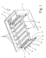
- the screening device 1 has a support frame 2 which is connected by means of an associated in Fig. 3 dashed vibratory drive 3 is set in vibration.
- the oscillating drive 3 is connected to the support frame 2 or from held this.
- the vibratory drive 3 can in particular as a balancing motor, directional vibratory drive or circular vibratory drive. In particular, it is about is a linear oscillator, that is, at least essentially only generates linear vibrations.
- the support frame 2 is mounted such that it can swing. This is the case with the illustration example the support frame 2 is supported by schematically indicated support springs 4 and especially mounted on it.
- spring elements 5 are supported, via which a swing frame 6 is resiliently coupled to the support frame 2.
- the spring elements 5 were or also run the swing frame 6 at the same time, so that additional Swing frame 6 with the support frame 2 connecting guide elements or the like. are not required.
- the swing frame 6 is mounted on the support frame 2 such that it is at least in essentially free in a tensioning shaft vibration direction 7 - that is, not positively controlled, but under the influence of the spring elements 5 - can move back and forth to to execute an oscillation referred to here as a tension shaft oscillation.
- a tension shaft oscillation Preferably can the swing frame 6 at least essentially exclusively in Swing the tension shaft oscillation direction 7.
- cross member 8 on the support frame 2 and on the swing frame 6 are arranged or mounted on these.
- the cross members 8 extend here at least essentially horizontally and transversely to the direction of the oscillating shaft vibration 7.
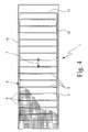
- the crossbeams 8 are one behind the other in the direction of the oscillation shaft 7 at least essentially arranged in one plane and alternately either carried by the support frame 2 or by the swing frame 6. If the Oscillating frame 6 oscillates back and forth in the tension shaft oscillation direction 7 accordingly, the distances between adjacent cross members 8 alternately enlarged and reduced.
- the sieve bottom elements or mats 9 are in particular individually replaceable and sufficiently flexible, as is generally known from the prior art.
- the swing frame 6 has four cross members 8 and is in the area of its end or transverse sides 10 of the spring elements 5th swinging mounted on the support frame 2.
- the spring elements 5 form bearing assemblies 11 for the swing frame 6, the structure of which will be explained in more detail later.
- a bearing assembly 11 in the area a transverse side 10 of the swing frame 6 is arranged.
- the swing frame 6 is here So only connected to the support frame 2 via two bearing assemblies 11 and above spring-elastic coupled for the execution of the expansion shaft vibration.
- the bearing assemblies 11 can, however, also be moved inwards from the transverse sides 10 be arranged.
- the screening device 1 can have a plurality of such, relatively short swing frames 6, which are arranged one behind the other and coupled to the same support frame 2 are.
- the screening device 1 can also be a "longer" one - that is, with more cross members 8 provided - swing frame 2, as in the variant 3 and 4.
- the swing frame is 6th for example, only supported on the support frame 2 again via two bearing assemblies 11 and swinging.
- more than two bearing assemblies can also be used 11 may be provided.
- each cross member for example, may be required 8 or every second cross member 8 of the swing frame 6 a bearing assembly 11 for storage of the swing frame 6 may be assigned. This enables the Using the same bearing assemblies 11 for different screening devices 1 with Vibration frames of different lengths 6.
- mounting flanges 13 at the ends to be attached are integrally formed.
- the mounting flanges 13 have, for example corresponding recesses or through holes on the edge on, so that the mounting flanges 13 in particular by means of not shown Screw connections can be connected to adjoining parts.
- the spring elements 5 are preferably solid and made of steel.
- the torsion about the torsion axis 12 on the one hand and sufficient spring hardness and resilience with respect to the load of the spring elements 5 across Torsion axis 12 in the vertical direction on the other hand - to reach the spring elements 5 preferably have a varying along their longitudinal axis Cross-section, which is formed the least, for example, in the middle his.
- the spring elements 5 (of course without considering the Mounting flanges 13) at least slightly conical, as in Fig. 2 not indicated to scale.
- the two are with the support frame 2 connected spring elements 5 preferably with their ends of larger cross section on the support frame 2 - by means of the mounting flanges 13 - attached.
- swivel arms 14 extend at least essentially here and at least in its neutral position, i.e. in the undeflected state, perpendicular to the direction of the oscillating shaft 7 towards the oscillating frame 6.
- the bearing assembly 11 is at least essentially between the swing frame 6 and below it arranged. Accordingly, the swivel arms 14 at least extend here essentially vertically upwards towards the swing frame 6.
- are here other constructive solutions are of course also possible.
- the swivel arms 14 are at their ends 15 facing the swing frame 6 the swing frame 6 - in particular with side members 16 of the swing frame 6 - articulated or pivotally connected.
- a swivel connection to the swing frame 6 in turn realized by spring elements 5.
- the swivel arms 14 in the region of their ends 15 also via a not shown Pivot bearing o. The like. Be connected to the swing frame 6.
- the "lower" - connected to the support frame 2 - spring elements 5 are replaced by the aforementioned swivel bearings or the like, if the remaining, "upper” - connected to the swing frame 6 - spring elements 5 have sufficient spring hardness to achieve the desired vibration behavior to be able to reach the screening device 1.
- the spring elements 5 close with their “thicker” - the larger cross section having - end to the associated pivot arm 14 in the region of its end 15 and extend in pairs with coaxial torsion axes 12 from each other away to the swing frame 6, where the spring elements 5 with their "thinner” ends via their mounting flanges 13 with the swing frame 6 or its side members 16 are connected.
- the swing frame 6 has a smaller width than that in the example shown Support frame 2 on or is arranged in this.
- the width difference can be adjusted by appropriate Spacers, intermediate washers or the like, not shown, are compensated.
- the pivot arms 14 are double, opposite cranked, as can be seen in FIG. 2, by the aforementioned width difference compensate.
- all spring elements 5 therefore extend one Bearing assembly 11 and in particular all spring elements 5 of all bearing assemblies 11 at least substantially parallel to one another, the spring elements 5 in each case are arranged in pairs coaxially and spaced apart.
- the two pivot arms 14 of a bearing assembly 11 are preferably over at least a torsionally rigid, in particular tubular connecting element 11 with each other connected.
- the connecting element 11 can also be used directly on the associated spring elements 5 or their fastening flanges 13 attack and so two spring elements 5 with coaxial torsion axes 12 together connect. In the latter case, the swivel arms 14 are in turn fixed to the connecting element 17 connected.
- two connecting elements 17 are provided, which are essentially between the upper spring elements 5 and the lower spring elements 5 one Bearing assembly 11 extend and so with the swivel arms 14 a trapezoidal Form stiffening element that on the one hand with the support frame via the spring elements 5 2 and on the other hand is connected to the swing frame 6.
- the connecting elements 17 are preferably screwed to the swivel arms 14, for example, that screws or bolts by assigned Fastening flanges 13 of spring elements 5 and corresponding sections the swivel arms 14 screwed into the connecting elements 17 are. This enables simple assembly and replacement of Components, if necessary.
- the swivel arms 14 and However, connecting elements 17 are also welded to one another or in some other way To be connected wisely.
- the stiffening caused by the connecting elements 17 leads to the wearing properties (Vertical load) and the spring properties (Torsion of the spring elements 5 for the tensioning shaft oscillating movement of the oscillating frame 6) a bearing assembly 11 on both sides with respect to the longitudinal axis of the Screening device 1 are largely the same, so that there is a symmetrical Vibration behavior of the vibrating frame 6 and the screening device 1 with respect to them Longitudinal axis results and a torsional vibration of the vibrating frame 6 around its Longitudinal axis is avoided.
- the aforementioned bearing assemblies 11 convey a in a simple manner effective guidance of the swing frame 6, the swing frame 6 relatively or at least sufficiently light in the direction of the vibrating shaft 7 can be moved back and forth. Due to the torsion of the spring elements 5 in the tension shaft vibration the vibrating frame 6 does not lead in a straight line or strictly Swinging movement, but moves on a slightly curved Circular path back and forth. However, since the deflection or vibration amplitude is proportional is small, in particular is approximately ⁇ 3.2 to 3.5 mm, the Swinging movement can be viewed at least essentially as linear. In addition Experiments have shown that this swinging wave oscillating movement is a very effective one Seven enables.
- a particular advantage of the proposed screening device 1 is that the Damping the vibration of the vibrating frame 6 relative to the support frame 2 is relatively low, so that relatively little damping work during operation must be applied and unnecessary heating of the moving or the elastically deforming parts, in particular the spring elements 5, avoided becomes.
- the swing frame 6 is at least essentially within the example shown of the support frame 2 arranged.
- longitudinal members 16 of the swing frame 6 arranged within the side cheeks of the support frame 2. This makes possible a simple structure, since the cross member 8 of the swing frame 6, the side cheeks of the support frame 2 do not penetrate.
- other designs are also possible.
- the tensioning shaft oscillation direction 7 or main extension plane of the oscillating frame 6 is in the representation example to the horizontal 18 in the direction of sieve 19, that is in the direction in which screenings are transported or conveyed via the screen tray elements 9 if it does not fall through the sieve plate elements 9, the Angle a inclined.
- the angle of inclination a is preferably approximately 3 ° to 5 °. This is surprisingly small, but is sufficient for the proposed screening device 1 for funding in the direction of sieve 19.
- the main vibration direction 20 of the vibration drive 3 exerted on the support frame 2 Vibration is against the direction of the screen 19 to the horizontal 18 around the Angle b inclined.
- the angle of inclination b here is preferably between 30 ° and 50 °, in particular essentially 40 °.
- the screening device 1 is preferably designed such that the resonance frequency at least 1100 vibrations per min. and in particular at least 1200 Vibrations per min. is. This enables subcritical operation of the Screening device 1, that is to say an oscillation below the resonance frequency, at opposite the prior art much higher vibration frequency.
- the proposed screening device 1 is preferably designed such that it with an oscillation frequency of at least 850 oscillations per min. and in particular with essentially 890 vibrations per min. or higher is operable.
- the vibratory drive 3 is designed accordingly.
- the vibrating frame 6 then executes a tensioning shaft vibration in the tensioning shaft vibration direction 7.
- the amplitude is in particular approximately ⁇ 3.2 to 3.5 mm. So are an average speed of the swing frame 6 relative to the support frame 2 of more than 11 m / min. and an average acceleration of at least 2.2 m / s 2 can be achieved. In this way, a much stronger clamping shaft vibration than in the prior art can be realized, which accordingly results in a more effective screening and a better conveying of screenings in the direction of screening 19.
- the spring elements 5 act as spiral springs.
- the natural frequency of the vibration system in these directions is far above the drive frequency. Correspondingly, this is done in these directions no resonant vibrations.
- the torsion bar spring-like spring elements 5 have a very high energy storage capacity on. Therefore, a large mass can be made with relatively few spring elements 5 are moved, whereby no damping occurs in comparison to push rubber elements and the frequency range is not due to self-heating and other influences, how temperature and aging are significantly restricted or changed. A Adaptation to the respective conditions can easily be done by varying the diameter and / or length of the spring elements 5.
- torsion bar spring elements 5 allows a completely revealing Choice of the vibration parameters and the size of the sieve device 1. Result So there is greater design freedom compared to the prior art.
Landscapes
- Combined Means For Separation Of Solids (AREA)
- Non-Silver Salt Photosensitive Materials And Non-Silver Salt Photography (AREA)
- Eye Examination Apparatus (AREA)
- Noodles (AREA)
Applications Claiming Priority (2)
| Application Number | Priority Date | Filing Date | Title |
|---|---|---|---|
| DE10016979 | 2000-04-06 | ||
| DE10016979A DE10016979C1 (de) | 2000-04-06 | 2000-04-06 | Siebvorrichtung |
Publications (3)
| Publication Number | Publication Date |
|---|---|
| EP1142651A2 true EP1142651A2 (fr) | 2001-10-10 |
| EP1142651A3 EP1142651A3 (fr) | 2002-09-18 |
| EP1142651B1 EP1142651B1 (fr) | 2004-11-10 |
Family
ID=7637706
Family Applications (1)
| Application Number | Title | Priority Date | Filing Date |
|---|---|---|---|
| EP01105640A Expired - Lifetime EP1142651B1 (fr) | 2000-04-06 | 2001-03-07 | Dispositif de tamisage |
Country Status (4)
| Country | Link |
|---|---|
| US (1) | US6666336B2 (fr) |
| EP (1) | EP1142651B1 (fr) |
| AT (1) | ATE281893T1 (fr) |
| DE (2) | DE10016979C1 (fr) |
Cited By (1)
| Publication number | Priority date | Publication date | Assignee | Title |
|---|---|---|---|---|
| WO2003045587A1 (fr) * | 2001-11-29 | 2003-06-05 | Binder + Co. Aktiengesellschaft | Dispositif cribleur |
Families Citing this family (15)
| Publication number | Priority date | Publication date | Assignee | Title |
|---|---|---|---|---|
| AT6073U1 (de) * | 2002-09-12 | 2003-04-25 | Binder Co Ag | Mehrdecksiebmaschine |
| DE102007003359A1 (de) * | 2007-01-17 | 2008-07-31 | Haver & Boecker Ohg | Schwingsiebmaschine |
| CA2726464C (fr) * | 2008-06-25 | 2015-03-31 | Brunes, Per | Convoyeur vibrant |
| GB2482686A (en) * | 2010-08-09 | 2012-02-15 | Crs Ni Ltd | Stationary wave separator |
| AT511949B1 (de) * | 2012-02-29 | 2013-04-15 | Ife Aufbereitungstechnik Gmbh | Spannwellensieb |
| DE102012214341A1 (de) * | 2012-08-10 | 2014-05-15 | Vibra Maschinenfabrik Schultheis Gmbh & Co. | Behandlungsvorrichtung für rieselfähiges Schüttgut |
| CN103240223B (zh) * | 2013-05-08 | 2015-05-20 | 中国矿业大学盱眙矿山装备与材料研发中心 | 双边扇形支撑弛张筛 |
| GB2527801A (en) * | 2014-07-02 | 2016-01-06 | Kieran Mckiver | Screen assembly |
| DE102014110055B4 (de) * | 2014-07-17 | 2020-03-19 | Spaleck GmbH & Co. Kommanditgesellschaft | Siebmaschine mit kassettenartigen Siebflächenabschnitten |
| AT517501B1 (de) * | 2015-07-21 | 2017-04-15 | Binder + Co Ag | Siebmaschine |
| US20180257013A1 (en) * | 2017-03-10 | 2018-09-13 | Grant Young | Shaker screen frame with circular member |
| CN107890979B (zh) * | 2017-10-10 | 2020-04-28 | 邱逸奎 | 一种旋转筛钩藤机 |
| CN111282805B (zh) * | 2020-02-20 | 2020-11-03 | 安徽昊华环保科技有限公司 | 一种高弹性自清洁不挂毛筛板 |
| CN113333269B (zh) * | 2021-04-27 | 2022-10-11 | 江西创驰橡胶有限公司 | 一种天然橡胶制备加工方法 |
| CN117920571B (zh) * | 2024-01-27 | 2024-07-26 | 江苏科赢应材科技有限公司 | 一种分级振动撒粉装置 |
Family Cites Families (11)
| Publication number | Priority date | Publication date | Assignee | Title |
|---|---|---|---|---|
| DE1206372B (de) | 1964-09-26 | 1965-12-09 | Albert Wehner | Siebrost |
| AT258791B (de) * | 1966-05-18 | 1967-12-11 | Binder Co Ag | Schwingtechnische Arbeitsmaschine mit einem Paar von gegensinnig schwingenden, durch Lenker verbundenen Massen |
| DE2918984C2 (de) | 1979-05-11 | 1982-06-09 | Uhde Gmbh, 4600 Dortmund | Vorrichtung zum Antrieb einer um ihre Längsachse schwingbar angeordneten Welle |
| AT377589B (de) * | 1981-08-28 | 1985-04-10 | Mueller Franz | Befestigungselement zum abhaengen von einrichtungen wie geraete, rohre u. dgl. |
| US4632751A (en) * | 1982-11-15 | 1986-12-30 | Johnson Louis W | Shaker screen |
| AT379088B (de) * | 1984-02-10 | 1985-11-11 | Binder Co Ag | Siebvorrichtung |
| DE3524895C1 (de) * | 1985-07-12 | 1986-12-18 | Hein, Lehmann AG, 4000 Düsseldorf | Siebmaschine |
| US5494173A (en) * | 1992-03-31 | 1996-02-27 | Deister Machine Co., Inc. | Vibrating screen apparatus for use in non-level operating conditions |
| AT400533B (de) * | 1992-12-11 | 1996-01-25 | Ife Gmbh | Spannwellensieb |
| RU2059449C1 (ru) | 1993-04-12 | 1996-05-10 | Воронежская государственная архитектурно-строительная академия | Просеивающее устройство |
| DE59401001D1 (de) | 1994-03-11 | 1996-12-12 | Hein Lehmann Trenn Foerder | Spannwellsiebmaschine |
-
2000
- 2000-04-06 DE DE10016979A patent/DE10016979C1/de not_active Expired - Lifetime
-
2001
- 2001-03-07 AT AT01105640T patent/ATE281893T1/de not_active IP Right Cessation
- 2001-03-07 EP EP01105640A patent/EP1142651B1/fr not_active Expired - Lifetime
- 2001-03-07 DE DE50104451T patent/DE50104451D1/de not_active Expired - Fee Related
- 2001-04-05 US US09/826,307 patent/US6666336B2/en not_active Expired - Fee Related
Cited By (2)
| Publication number | Priority date | Publication date | Assignee | Title |
|---|---|---|---|---|
| WO2003045587A1 (fr) * | 2001-11-29 | 2003-06-05 | Binder + Co. Aktiengesellschaft | Dispositif cribleur |
| US7195121B2 (en) | 2001-11-29 | 2007-03-27 | Binder + Co. Aktiengesellschaft | Sifting device |
Also Published As
| Publication number | Publication date |
|---|---|
| EP1142651B1 (fr) | 2004-11-10 |
| DE10016979C1 (de) | 2001-08-30 |
| US6666336B2 (en) | 2003-12-23 |
| EP1142651A3 (fr) | 2002-09-18 |
| ATE281893T1 (de) | 2004-11-15 |
| DE50104451D1 (de) | 2004-12-16 |
| US20010040119A1 (en) | 2001-11-15 |
Similar Documents
| Publication | Publication Date | Title |
|---|---|---|
| EP1142651B1 (fr) | Dispositif de tamisage | |
| DE2051626C3 (de) | Schwingungsdämpfer | |
| DE3128349C2 (fr) | ||
| EP1120170B1 (fr) | Dispositif de tamisage | |
| EP2208693B1 (fr) | Convoyeur linéaire de vibrations | |
| EP3746231B1 (fr) | Dispositif de tamisage | |
| WO2003045587A1 (fr) | Dispositif cribleur | |
| DE102008008100A1 (de) | Vibrationsdämpfende Vorrichtung | |
| DE3503125C2 (de) | Siebvorrichtung | |
| DE10118440C2 (de) | Lageranordnung zur pendelnden Aufhängung des Schwingrahmens eines Förderrostes | |
| EP0405477B1 (fr) | Appareil de tamisage | |
| EP3763966A1 (fr) | Ensemble de suspension et transporteur à vibrations | |
| EP1899245B1 (fr) | Transporteur vibrant lineaire | |
| DE3512215A1 (de) | Siebmaschine mit einem flexiblen siebbelag | |
| EP0350830B1 (fr) | Appareil cribleur | |
| EP1327726B1 (fr) | Dispositif amortisseur de vibrations règlable | |
| EP2578519B1 (fr) | Transporteur linéaire à vibrations | |
| DE723311C (de) | Einrichtung an Schwingsieben, Foerderrinnen u. dgl. | |
| AT400533B (de) | Spannwellensieb | |
| DE1091035B (de) | Durch Lenker gefuehrter Schwingfoerderer | |
| DE2135323A1 (de) | Schwingsieb, insbesondere schwingsieb fuer die feinabsiebung | |
| DE10015706B4 (de) | Linear-Schwingförderer | |
| AT211222B (de) | Schwingförderer zur Beförderung in einer Richtung | |
| DE1456539C (de) | Schwingförderer für Tabak | |
| DE2463161C2 (de) | Schondeck für linear schwingende Siebmaschinen |
Legal Events
| Date | Code | Title | Description |
|---|---|---|---|
| PUAI | Public reference made under article 153(3) epc to a published international application that has entered the european phase |
Free format text: ORIGINAL CODE: 0009012 |
|
| AK | Designated contracting states |
Kind code of ref document: A2 Designated state(s): AT BE CH CY DE DK ES FI FR GB GR IE IT LI LU MC NL PT SE TR |
|
| AX | Request for extension of the european patent |
Free format text: AL;LT;LV;MK;RO;SI |
|
| PUAL | Search report despatched |
Free format text: ORIGINAL CODE: 0009013 |
|
| AK | Designated contracting states |
Kind code of ref document: A3 Designated state(s): AT BE CH CY DE DK ES FI FR GB GR IE IT LI LU MC NL PT SE TR |
|
| AX | Request for extension of the european patent |
Free format text: AL;LT;LV;MK;RO;SI |
|
| 17P | Request for examination filed |
Effective date: 20020910 |
|
| AKX | Designation fees paid |
Designated state(s): AT BE CH CY DE DK ES FI FR GB GR IE IT LI LU MC NL PT SE TR |
|
| 17Q | First examination report despatched |
Effective date: 20031211 |
|
| GRAP | Despatch of communication of intention to grant a patent |
Free format text: ORIGINAL CODE: EPIDOSNIGR1 |
|
| GRAS | Grant fee paid |
Free format text: ORIGINAL CODE: EPIDOSNIGR3 |
|
| GRAA | (expected) grant |
Free format text: ORIGINAL CODE: 0009210 |
|
| AK | Designated contracting states |
Kind code of ref document: B1 Designated state(s): AT BE CH CY DE DK ES FI FR GB GR IE IT LI LU MC NL PT SE TR |
|
| PG25 | Lapsed in a contracting state [announced via postgrant information from national office to epo] |
Ref country code: TR Free format text: LAPSE BECAUSE OF FAILURE TO SUBMIT A TRANSLATION OF THE DESCRIPTION OR TO PAY THE FEE WITHIN THE PRESCRIBED TIME-LIMIT Effective date: 20041110 Ref country code: NL Free format text: LAPSE BECAUSE OF FAILURE TO SUBMIT A TRANSLATION OF THE DESCRIPTION OR TO PAY THE FEE WITHIN THE PRESCRIBED TIME-LIMIT Effective date: 20041110 Ref country code: FI Free format text: LAPSE BECAUSE OF FAILURE TO SUBMIT A TRANSLATION OF THE DESCRIPTION OR TO PAY THE FEE WITHIN THE PRESCRIBED TIME-LIMIT Effective date: 20041110 Ref country code: IE Free format text: LAPSE BECAUSE OF FAILURE TO SUBMIT A TRANSLATION OF THE DESCRIPTION OR TO PAY THE FEE WITHIN THE PRESCRIBED TIME-LIMIT Effective date: 20041110 |
|
| REG | Reference to a national code |
Ref country code: GB Ref legal event code: FG4D Free format text: NOT ENGLISH |
|
| REG | Reference to a national code |
Ref country code: CH Ref legal event code: EP |
|
| REG | Reference to a national code |
Ref country code: IE Ref legal event code: FG4D Free format text: GERMAN |
|
| REF | Corresponds to: |
Ref document number: 50104451 Country of ref document: DE Date of ref document: 20041216 Kind code of ref document: P |
|
| PG25 | Lapsed in a contracting state [announced via postgrant information from national office to epo] |
Ref country code: GR Free format text: LAPSE BECAUSE OF FAILURE TO SUBMIT A TRANSLATION OF THE DESCRIPTION OR TO PAY THE FEE WITHIN THE PRESCRIBED TIME-LIMIT Effective date: 20050210 Ref country code: DK Free format text: LAPSE BECAUSE OF FAILURE TO SUBMIT A TRANSLATION OF THE DESCRIPTION OR TO PAY THE FEE WITHIN THE PRESCRIBED TIME-LIMIT Effective date: 20050210 Ref country code: SE Free format text: LAPSE BECAUSE OF FAILURE TO SUBMIT A TRANSLATION OF THE DESCRIPTION OR TO PAY THE FEE WITHIN THE PRESCRIBED TIME-LIMIT Effective date: 20050210 |
|
| PG25 | Lapsed in a contracting state [announced via postgrant information from national office to epo] |
Ref country code: ES Free format text: LAPSE BECAUSE OF FAILURE TO SUBMIT A TRANSLATION OF THE DESCRIPTION OR TO PAY THE FEE WITHIN THE PRESCRIBED TIME-LIMIT Effective date: 20050221 |
|
| GBT | Gb: translation of ep patent filed (gb section 77(6)(a)/1977) |
Effective date: 20050131 |
|
| PG25 | Lapsed in a contracting state [announced via postgrant information from national office to epo] |
Ref country code: CY Free format text: LAPSE BECAUSE OF FAILURE TO SUBMIT A TRANSLATION OF THE DESCRIPTION OR TO PAY THE FEE WITHIN THE PRESCRIBED TIME-LIMIT Effective date: 20050307 Ref country code: LU Free format text: LAPSE BECAUSE OF NON-PAYMENT OF DUE FEES Effective date: 20050307 |
|
| PG25 | Lapsed in a contracting state [announced via postgrant information from national office to epo] |
Ref country code: MC Free format text: LAPSE BECAUSE OF NON-PAYMENT OF DUE FEES Effective date: 20050331 Ref country code: CH Free format text: LAPSE BECAUSE OF NON-PAYMENT OF DUE FEES Effective date: 20050331 Ref country code: BE Free format text: LAPSE BECAUSE OF NON-PAYMENT OF DUE FEES Effective date: 20050331 Ref country code: LI Free format text: LAPSE BECAUSE OF NON-PAYMENT OF DUE FEES Effective date: 20050331 |
|
| NLV1 | Nl: lapsed or annulled due to failure to fulfill the requirements of art. 29p and 29m of the patents act | ||
| PLAQ | Examination of admissibility of opposition: information related to despatch of communication + time limit deleted |
Free format text: ORIGINAL CODE: EPIDOSDOPE2 |
|
| PLBI | Opposition filed |
Free format text: ORIGINAL CODE: 0009260 |
|
| PLBQ | Unpublished change to opponent data |
Free format text: ORIGINAL CODE: EPIDOS OPPO |
|
| PLAQ | Examination of admissibility of opposition: information related to despatch of communication + time limit deleted |
Free format text: ORIGINAL CODE: EPIDOSDOPE2 |
|
| PLAR | Examination of admissibility of opposition: information related to receipt of reply deleted |
Free format text: ORIGINAL CODE: EPIDOSDOPE4 |
|
| PLBQ | Unpublished change to opponent data |
Free format text: ORIGINAL CODE: EPIDOS OPPO |
|
| REG | Reference to a national code |
Ref country code: IE Ref legal event code: FD4D |
|
| PLAB | Opposition data, opponent's data or that of the opponent's representative modified |
Free format text: ORIGINAL CODE: 0009299OPPO |
|
| 26 | Opposition filed |
Opponent name: HEIN, LEHMANN TRENN-UND FOERDERTECHNIK GMBH Effective date: 20050616 |
|
| ET | Fr: translation filed | ||
| R26 | Opposition filed (corrected) |
Opponent name: HEIN, LEHMANN TRENN-UND FOERDERTECHNIK GMBH Effective date: 20050616 |
|
| PLAX | Notice of opposition and request to file observation + time limit sent |
Free format text: ORIGINAL CODE: EPIDOSNOBS2 |
|
| BERE | Be: lapsed |
Owner name: JOST G.M.B.H. + CO. KG Effective date: 20050331 |
|
| REG | Reference to a national code |
Ref country code: CH Ref legal event code: PL |
|
| PLAF | Information modified related to communication of a notice of opposition and request to file observations + time limit |
Free format text: ORIGINAL CODE: EPIDOSCOBS2 |
|
| PLBB | Reply of patent proprietor to notice(s) of opposition received |
Free format text: ORIGINAL CODE: EPIDOSNOBS3 |
|
| PLCK | Communication despatched that opposition was rejected |
Free format text: ORIGINAL CODE: EPIDOSNREJ1 |
|
| BERE | Be: lapsed |
Owner name: *JOST G.M.B.H. + CO. K.G. Effective date: 20050331 |
|
| PG25 | Lapsed in a contracting state [announced via postgrant information from national office to epo] |
Ref country code: PT Free format text: LAPSE BECAUSE OF NON-PAYMENT OF DUE FEES Effective date: 20050410 |
|
| PLBN | Opposition rejected |
Free format text: ORIGINAL CODE: 0009273 |
|
| STAA | Information on the status of an ep patent application or granted ep patent |
Free format text: STATUS: OPPOSITION REJECTED |
|
| 27O | Opposition rejected |
Effective date: 20070919 |
|
| PGFP | Annual fee paid to national office [announced via postgrant information from national office to epo] |
Ref country code: GB Payment date: 20080320 Year of fee payment: 8 Ref country code: IT Payment date: 20080326 Year of fee payment: 8 |
|
| PGFP | Annual fee paid to national office [announced via postgrant information from national office to epo] |
Ref country code: AT Payment date: 20080314 Year of fee payment: 8 |
|
| PGFP | Annual fee paid to national office [announced via postgrant information from national office to epo] |
Ref country code: DE Payment date: 20071204 Year of fee payment: 8 Ref country code: FR Payment date: 20080314 Year of fee payment: 8 |
|
| PG25 | Lapsed in a contracting state [announced via postgrant information from national office to epo] |
Ref country code: AT Free format text: LAPSE BECAUSE OF NON-PAYMENT OF DUE FEES Effective date: 20090307 |
|
| GBPC | Gb: european patent ceased through non-payment of renewal fee |
Effective date: 20090307 |
|
| REG | Reference to a national code |
Ref country code: FR Ref legal event code: ST Effective date: 20091130 |
|
| PG25 | Lapsed in a contracting state [announced via postgrant information from national office to epo] |
Ref country code: DE Free format text: LAPSE BECAUSE OF NON-PAYMENT OF DUE FEES Effective date: 20091001 |
|
| PG25 | Lapsed in a contracting state [announced via postgrant information from national office to epo] |
Ref country code: GB Free format text: LAPSE BECAUSE OF NON-PAYMENT OF DUE FEES Effective date: 20090307 Ref country code: FR Free format text: LAPSE BECAUSE OF NON-PAYMENT OF DUE FEES Effective date: 20091123 |
|
| PG25 | Lapsed in a contracting state [announced via postgrant information from national office to epo] |
Ref country code: IT Free format text: LAPSE BECAUSE OF NON-PAYMENT OF DUE FEES Effective date: 20090307 |