EP1142797A2 - Panneau de separation amovible pour emballage d'articles sur plusieurs couches - Google Patents
Panneau de separation amovible pour emballage d'articles sur plusieurs couches Download PDFInfo
- Publication number
- EP1142797A2 EP1142797A2 EP01201596A EP01201596A EP1142797A2 EP 1142797 A2 EP1142797 A2 EP 1142797A2 EP 01201596 A EP01201596 A EP 01201596A EP 01201596 A EP01201596 A EP 01201596A EP 1142797 A2 EP1142797 A2 EP 1142797A2
- Authority
- EP
- European Patent Office
- Prior art keywords
- carton
- panel
- flap
- divider panel
- cans
- Prior art date
- Legal status (The legal status is an assumption and is not a legal conclusion. Google has not performed a legal analysis and makes no representation as to the accuracy of the status listed.)
- Withdrawn
Links
Images



Classifications
-
- B—PERFORMING OPERATIONS; TRANSPORTING
- B65—CONVEYING; PACKING; STORING; HANDLING THIN OR FILAMENTARY MATERIAL
- B65D—CONTAINERS FOR STORAGE OR TRANSPORT OF ARTICLES OR MATERIALS, e.g. BAGS, BARRELS, BOTTLES, BOXES, CANS, CARTONS, CRATES, DRUMS, JARS, TANKS, HOPPERS, FORWARDING CONTAINERS; ACCESSORIES, CLOSURES, OR FITTINGS THEREFOR; PACKAGING ELEMENTS; PACKAGES
- B65D71/00—Bundles of articles held together by packaging elements for convenience of storage or transport, e.g. portable segregating carrier for plural receptacles such as beer cans or pop bottles; Bales of material
- B65D71/06—Packaging elements holding or encircling completely or almost completely the bundle of articles, e.g. wrappers
- B65D71/12—Packaging elements holding or encircling completely or almost completely the bundle of articles, e.g. wrappers the packaging elements, e.g. wrappers being formed by folding a single blank
- B65D71/36—Packaging elements holding or encircling completely or almost completely the bundle of articles, e.g. wrappers the packaging elements, e.g. wrappers being formed by folding a single blank having a tubular shape, e.g. tubular wrappers, with end walls
-
- B—PERFORMING OPERATIONS; TRANSPORTING
- B65—CONVEYING; PACKING; STORING; HANDLING THIN OR FILAMENTARY MATERIAL
- B65D—CONTAINERS FOR STORAGE OR TRANSPORT OF ARTICLES OR MATERIALS, e.g. BAGS, BARRELS, BOTTLES, BOXES, CANS, CARTONS, CRATES, DRUMS, JARS, TANKS, HOPPERS, FORWARDING CONTAINERS; ACCESSORIES, CLOSURES, OR FITTINGS THEREFOR; PACKAGING ELEMENTS; PACKAGES
- B65D2571/00—Bundles of articles held together by packaging elements for convenience of storage or transport, e.g. portable segregating carrier for plural receptacles such as beer cans, pop bottles; Bales of material
- B65D2571/00123—Bundling wrappers or trays
- B65D2571/00129—Wrapper locking means
- B65D2571/00135—Wrapper locking means integral with the wrapper
- B65D2571/00141—Wrapper locking means integral with the wrapper glued
-
- B—PERFORMING OPERATIONS; TRANSPORTING
- B65—CONVEYING; PACKING; STORING; HANDLING THIN OR FILAMENTARY MATERIAL
- B65D—CONTAINERS FOR STORAGE OR TRANSPORT OF ARTICLES OR MATERIALS, e.g. BAGS, BARRELS, BOTTLES, BOXES, CANS, CARTONS, CRATES, DRUMS, JARS, TANKS, HOPPERS, FORWARDING CONTAINERS; ACCESSORIES, CLOSURES, OR FITTINGS THEREFOR; PACKAGING ELEMENTS; PACKAGES
- B65D2571/00—Bundles of articles held together by packaging elements for convenience of storage or transport, e.g. portable segregating carrier for plural receptacles such as beer cans, pop bottles; Bales of material
- B65D2571/00123—Bundling wrappers or trays
- B65D2571/00333—Partitions, i.e. elements contacting a major part of each aarticle or extending across the whole length of the wrapper
- B65D2571/00401—Partitions, i.e. elements contacting a major part of each aarticle or extending across the whole length of the wrapper inserted the wrapper
-
- B—PERFORMING OPERATIONS; TRANSPORTING
- B65—CONVEYING; PACKING; STORING; HANDLING THIN OR FILAMENTARY MATERIAL
- B65D—CONTAINERS FOR STORAGE OR TRANSPORT OF ARTICLES OR MATERIALS, e.g. BAGS, BARRELS, BOTTLES, BOXES, CANS, CARTONS, CRATES, DRUMS, JARS, TANKS, HOPPERS, FORWARDING CONTAINERS; ACCESSORIES, CLOSURES, OR FITTINGS THEREFOR; PACKAGING ELEMENTS; PACKAGES
- B65D2571/00—Bundles of articles held together by packaging elements for convenience of storage or transport, e.g. portable segregating carrier for plural receptacles such as beer cans, pop bottles; Bales of material
- B65D2571/00123—Bundling wrappers or trays
- B65D2571/00432—Handles or suspending means
- B65D2571/00456—Handles or suspending means integral with the wrapper
- B65D2571/00469—Straps made between two handholes
-
- B—PERFORMING OPERATIONS; TRANSPORTING
- B65—CONVEYING; PACKING; STORING; HANDLING THIN OR FILAMENTARY MATERIAL
- B65D—CONTAINERS FOR STORAGE OR TRANSPORT OF ARTICLES OR MATERIALS, e.g. BAGS, BARRELS, BOTTLES, BOXES, CANS, CARTONS, CRATES, DRUMS, JARS, TANKS, HOPPERS, FORWARDING CONTAINERS; ACCESSORIES, CLOSURES, OR FITTINGS THEREFOR; PACKAGING ELEMENTS; PACKAGES
- B65D2571/00—Bundles of articles held together by packaging elements for convenience of storage or transport, e.g. portable segregating carrier for plural receptacles such as beer cans, pop bottles; Bales of material
- B65D2571/00123—Bundling wrappers or trays
- B65D2571/00432—Handles or suspending means
- B65D2571/00537—Handles or suspending means with stress relieving means
- B65D2571/00549—Handles or suspending means with stress relieving means consisting of fold lines
-
- B—PERFORMING OPERATIONS; TRANSPORTING
- B65—CONVEYING; PACKING; STORING; HANDLING THIN OR FILAMENTARY MATERIAL
- B65D—CONTAINERS FOR STORAGE OR TRANSPORT OF ARTICLES OR MATERIALS, e.g. BAGS, BARRELS, BOTTLES, BOXES, CANS, CARTONS, CRATES, DRUMS, JARS, TANKS, HOPPERS, FORWARDING CONTAINERS; ACCESSORIES, CLOSURES, OR FITTINGS THEREFOR; PACKAGING ELEMENTS; PACKAGES
- B65D2571/00—Bundles of articles held together by packaging elements for convenience of storage or transport, e.g. portable segregating carrier for plural receptacles such as beer cans, pop bottles; Bales of material
- B65D2571/00123—Bundling wrappers or trays
- B65D2571/00555—Wrapper opening devices
- B65D2571/00561—Lines of weakness
- B65D2571/00574—Lines of weakness whereby contents can still be carried after the line has been torn
-
- B—PERFORMING OPERATIONS; TRANSPORTING
- B65—CONVEYING; PACKING; STORING; HANDLING THIN OR FILAMENTARY MATERIAL
- B65D—CONTAINERS FOR STORAGE OR TRANSPORT OF ARTICLES OR MATERIALS, e.g. BAGS, BARRELS, BOTTLES, BOXES, CANS, CARTONS, CRATES, DRUMS, JARS, TANKS, HOPPERS, FORWARDING CONTAINERS; ACCESSORIES, CLOSURES, OR FITTINGS THEREFOR; PACKAGING ELEMENTS; PACKAGES
- B65D2571/00—Bundles of articles held together by packaging elements for convenience of storage or transport, e.g. portable segregating carrier for plural receptacles such as beer cans, pop bottles; Bales of material
- B65D2571/00123—Bundling wrappers or trays
- B65D2571/00648—Elements used to form the wrapper
- B65D2571/00654—Blanks
- B65D2571/0066—Blanks formed from one single sheet
-
- B—PERFORMING OPERATIONS; TRANSPORTING
- B65—CONVEYING; PACKING; STORING; HANDLING THIN OR FILAMENTARY MATERIAL
- B65D—CONTAINERS FOR STORAGE OR TRANSPORT OF ARTICLES OR MATERIALS, e.g. BAGS, BARRELS, BOTTLES, BOXES, CANS, CARTONS, CRATES, DRUMS, JARS, TANKS, HOPPERS, FORWARDING CONTAINERS; ACCESSORIES, CLOSURES, OR FITTINGS THEREFOR; PACKAGING ELEMENTS; PACKAGES
- B65D2571/00—Bundles of articles held together by packaging elements for convenience of storage or transport, e.g. portable segregating carrier for plural receptacles such as beer cans, pop bottles; Bales of material
- B65D2571/00123—Bundling wrappers or trays
- B65D2571/00709—Shape of the formed wrapper, i.e. shape of each formed element if the wrapper is made from more than one element
- B65D2571/00722—Shape of the formed wrapper, i.e. shape of each formed element if the wrapper is made from more than one element tubular with end walls, e.g. walls not extending on the whole end surface
- B65D2571/00728—Shape of the formed wrapper, i.e. shape of each formed element if the wrapper is made from more than one element tubular with end walls, e.g. walls not extending on the whole end surface the end walls being closed by gluing
Definitions
- the invention relates generally to packages of articles such as beverage cans or similar containers arranged in two or more tiers separated by a divider panel, and more particularly to means for removing the divider panel from the package to gain access to the lower tier of beverages after the upper tier has been removed.
- a divider panel is useful in a package encasing two or more tiers to separate the bottoms of one tier of articles from the tops of a lower tier of articles. Separation of tiers of articles provides a stronger, more reliable overall package. In many instances it is simply undesirable for articles, such as cans, for the cans of one tier to be in contact with the cans of another tier.
- the ends of the divider panel may be anchored by an adhesive or other means to the inner surface of the carton to prevent unwanted movement of the panel and to increase the overall stability of the package.
- an adhesive or other means to the inner surface of the carton to prevent unwanted movement of the panel and to increase the overall stability of the package.
- Stout shows the use of a divider panel in a double tier carton.
- beverage cans or other encased articles may be removed from the package through an opening in the carton created by lifting a flap.
- cans are normally removed first from the topmost tier through the opening in the carton wall.
- the anchored divider panel must be removed to gain access to the cans on a lower tier of the package.
- the divider panel is useful for segregating successive tiers of cans, it also prevents access to lower tiers of cans when the package is used as a dispenser.
- a divider panel for a multiple-tier package that may be easily removed to gain access to a tier of cans beneath the divider panel.
- One aspect of the invention provides a carton for multiple tiers of containers having a removable divider panel separating the tiers.
- the carton comprising a bottom wall, a top wall and a pair of spaced apart side walls interconnecting said top and bottom walls thereby forming a tubular structure, at least one end flap at each end of said tubular structure forming a closure structure, opening means formed within at least one of the bottom wall, the top wall or the side walls.
- means for releasably securing the divider panel within the carton comprises an anchor flap foldably and detachably joined to the front edge of the divider panel.
- the means for securing the divider panel are adhesively secured to respective end closure structures.
- the divider panel may comprise a major panel having an area generally equal to a cross-sectional area of one tier of the group of at least two vertically-disposed tiers of the containers and having a front edge and a rear edge, and having a plurality of score lines non-convergingly extending from the front edge generally toward the rear edge such that the major panel may be curled about the scored lines, at least one aperture positioned so that when the major panel is disposed within the carton over a lower tier of containers arranged in an array, each of the apertures is aligned over a space between an adjacent pair of containers.
- At least one aperture may contain a tab removably positioned within the aperture.
- the at least one aperture may be proximate the front edge of the major panel.
- the major panel may have a perimeter configuration generally corresponding to a perimeter configuration of the cross-section of the carton.
- the plurality of scored lines may comprise a first pair of parallel scored lines parallel to opposed side edges of the major panel and at least one skewed scored line extending from the front edge of the major panel intermediate one of the first pair of parallel scored lines and an adjacent side edge of the major panel towards the adjacent side edge.
- the plurality of scored lines may include a pair of opposed skewed scored lines beginning at the front edge of the major panel and wherein the pair of opposed skewed scored lines extend through the0 anchor flap which is foldably and detachably joined to the front edge of the major panel.
- first anchor flap may have first oblique side edges.
- the means for releasably securing the divider panel within the carton may further comprise a second anchor flap foldably and detachably joined to the rear edge of the divider panel.
- the second anchor flap may have second oblique side edges and a pair of secondary parallel scored lines coincident with the first and second parallel scored lines.
- the first pair of parallel scored lines may extend through the anchor flap which is foldably and detachably joined to the rear edge of the major panel.
- a leading edge of one of the first and second anchor flaps may be nestable with a leading edge of an other of the first and second anchor flaps.
- a leading edge of one of the first and second anchor flaps may define a notch and a leading edge of an other of the first and second anchor flaps defines a protrusion nestable with the notch.
- a wall panel of the carton may have a tear-away flap which is integrally formed with an end closure of the carton and which is attached to an anchor flap of the divider panel and wherein the divider panel is removable from the carton by tearing away the tear-away flap from its end closure to sever the connection between the tear-away flap and the divider panel whereafter the divider panel may be withdrawn from the carton through the opening created by removal of the tear-away flap.
- a second aspect of the invention provides a package comprising a plurality of beverage cans arranged into a group of at least two vertically-aligned tiers, each of the cans having a generally cylindrical side wall defining a cylindrical axis.
- the cans in each of the tiers having the axes thereof disposed vertically and parallel to each other.
- a third aspect of the invention provides a multiple-tier article carton in which a divider panel is disposed between adjacent tiers of articles and wherein a wall panel of the carton has a tear-away flap which is integrally formed with an end closure of the carton and which is attached to an anchor flap of the divider panel.
- the divider panel is removable from the carton by tearing away the tear-away flap from its end closure to sever the connection between the tear-away flap and the divider panel whereafter the divider panel may be withdrawn from the carton through the opening created by removal of the tear-away flap.
- a fourth aspect of the invention provides a carton disposed around an exterior of the group of cans and including top and bottom panels interconnected by a pair of side panels to form a tubular structure, and a pair of end closure structures disposed to close opposite ends of the tubular structure.
- the end closure structures are connected to the tubular structure and are disposed substantially adjacent the side walls of the cans of the group along opposite ends of the group.
- At least one of the side panels and the end closure structures have a removable flap opening for removing the cans from the carton, and a divider panel disposed between upper and lower adjacent of the tiers and in contact with the cans in the upper and lower adjacent tiers.
- the divider panel has a major panel having an area generally equal to a cross-sectional area of a lower tier of the group of at least two vertically-aligned tiers, having a front edge proximate the removable flap opening of the carton and an opposing rear edge, having a plurality of scored lines extending between the front and rear edges such that the major panel may be curled about the scored lines, defining at least one aperture proximate the front edge positioned over a lower of the tiers of cans such that the apertures are aligned over spaces between adjacent cans of the lower of the tiers of cans; and means for securing the major panel within the carton.
- the present invention is intended primarily for use in separating adjacent tiers of articles in a paperboard carton forming a multiple-tier package.
- the invention is particularly suitable for use with multiple tiers of aluminum or steel beverage cans and, although more broadly applicable, for convenience will be explained in this context.
- a typical can is denoted throughout the drawings by the numeral 10.
- the typical can 10 generally has a single-piece, seamless drawn body with a top lid and a lower covered end.
- the top lid is generally recessed within a peripheral flange.
- the divider panel is constructed so that it may be easily withdrawn through an opening in the carton through which individual cans may be removed.
- the removable divider panel of the preferred embodiment of the invention is designed to enable a main panel to be torn away from anchor flaps which secure the panel in the carton.
- the divider panel is also designed to bend in a manner that makes removal easier.
- the divider panel is described for use in conjunction with typical cartons, it will be clearly understood that the panel of the invention may be used with cartons having configurations differing from those described herein.
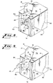
- a removable divider panel 20 for a multiple-tier can package according to a preferred embodiment of the invention.
- Figs. 1 and 2 may be referred to simultaneously.
- the divider panel 20 illustrated is suitable for use with an elongated array of cans 10 such as the 3 x 4 array shown in Fig. 2.
- the divider panel 20 has a major panel 22 with an anchor flap 24, 26 attached at either end of the main panel 22 along respective perforated fold lines 23.
- the ends of the divider panel 20 and the anchor flaps 24, 26 may be shaped to create a rectangular or otherwise overall rectilinear divider panel, the corners of the major panel 22 of the divider panel 20 are bevelled and coincide with the inclined edges of the anchor flaps 24, 26.
- the bevelled corners of the divider panel 20 are configured to correspond to a carton having bevelled corners but are also suitable for a carton having square corners. The relationship between the carton and the divider panel 20 is discussed in greater detail below.
- the anchor flaps 24, 26 may be rectilinear but are shown in a configuration that permits maximum extension of each flap 24, 26 from its line of connection 23 at the major panel 22 while requiring as little construction material as possible.
- the inclined side edges of the anchor flaps 24, 26 cut off the corners of the anchor flaps 24, 26, thereby reducing the amount of material such as paperboard needed to produce the divider panel 20.
- the amount of material necessary to produce the anchor flaps 24, 26 (and divider panel 20) is further optimized by the corresponding nesting configuration of the opposing anchor flaps 24, 26.
- the leading edge 25 of one anchor flap 24 has an indentation while the leading edge 27 of the opposite anchor flap 26 has a protrusion corresponding to the indented edge 25.
- the protrusion of the protruding edge 27 of the anchor flap 26 likewise creates maximum extension beyond the fold line 23 while utilizing minimum material.
- the corresponding indented 25 and protruding 27 edges also permit the panels 20 to be cut from a sheet of material in a nested fashion whereby the indented edge 25 of the anchor flap 24 of one divider panel 20 nests with the protruding edge 27 of the anchor flap 26 of another divider panel 20 being cut from the same sheet of material. This nested manufacturing process minimizes waste of unused material.
- the divider panel 20 is scored with lines that facilitate bending of the divider panel 20 about the scored lines. Although these scored lines may be arranged in many different patterns, the preferred embodiment illustrates an arrangement of a set of scored lines 28, 30, 32, 34, 36 that generally radiate from points on one of the fold lines 23. As will be discussed in greater detail below, when the divider panel 20 is positioned within a carton for use, the anchor flaps 24, 26 are folded downward and the fold lines 23 between the major panel 22 and the anchor flaps 24, 26 abut the inner walls of the carton. The fold line 23 from which the scored lines 28, 30 ,32, 34, 36 radiate becomes the end of the major panel 22 that will be removed first from the carton.
- an innermost set of scored lines 28 is essentially parallel to the sides of the major panel 22 while the two additional sets of scored lines 30, 32 radiate in a divergent pattern along the length of the divider panel 20.
- What may be considered a set of converging scored lines 34 extend through one of the anchor flaps 24 and coincide with one of the diverging sets of scored lines 30.
- the scored lines 34 in the anchor flap 24 are useful for promoting bending of the anchor flap 24 if the major panel 22 is to be removed from the carton without first detaching that anchor flap 24.
- a set of parallel scored lines extend through the second anchor flap 36 and coincide with the parallel lines 28 of the major panel.
- the scored lines 36 in the anchor flap 26 are useful for promoting bending of the end flap 26 if the major panel 22 is to be removed from the carton without first detaching that anchor flap 26.
- a pair of apertures are formed in the major panel 22 by perforated cut lines 37.
- the apertures 37 become accessible by removing punch-out tabs 38 which remain connected to the major panel 22 of the divider panel 20 by scored fold lines 39.
- the apertures 37 are positioned upon the divider panel 20 such that they are aligned over the spacing formed between adjoining cans 10 of an array when the divider panel 20 is placed over that array of cans 10.
- Fig. 1 depicts in phantom form representative cans 10 of a tier upon which the panel 20 rests.
- Fig. 2 therein is shown a manner in which the divider panel 20 may be positioned for use between two tiers of cans 10 in 3 x 4 arrays.
- the panel 20 is positioned over the bottom tier of cans 10 so that the apertures 37 and punch-outs 38 are aligned over spaces between the tops and sides of the cans 10 of the first and second rows of the bottom tier.
- the upper tier of cans 10 may then be positioned over the lower tier, as shown in Fig. 3.
- Figs. 2 and 3 also illustrate the manner in which the anchor flaps 24, 26 (only one anchor flap 24 is visible in the views of Figs.
- divider panel 20 is designed to be withdrawn through an opening in the erected carton.
- the panel will be described as being withdrawn through the opening created by removing the end opening flap 12.
- the end opening flap 12 is defined by tear lines 13 inscribed in the end 66 and top 42 panels.
- a primary tear initiation slit 14 facilitates tearing open of the end opening flap 12.
- a fold line 15 for the end opening flap 12 extends between the tear lines 13. Tearing open of the end opening flap 12 is further facilitated by and may be initiated through a tear initiation tab 16 defined by primary tear initiation slit 14, secondary tear initiation slit 18 and tear fold line 17.
- the central body of the carton is formed from central panels 40, 42, 48, 52, 56. The central panels are connected to one another by various respective fold lines 44, 46, 50, 54.
- the end walls of the erected carton are formed from end panels 58, 60, 66, 68, 74, 76, 82, 84, 90, 92 connected along respective fold lines 62, 64, 70, 72, 78, 80, 86, 88, 94, 96 at the sides of respective central panels 40, 42, 48, 52, 56.
- bevelled corner panels 102 become bevelled corners of the erected carton.
- the corners of the divider panel 20 may bevelled to accommodate a carton having bevelled corners.
- the bevelled corner panels 102 are created by the addition of fold lines 100 parallel to the fold lines 78, 80, 86, 88, 94, 96 between end panels 74, 76, 82, 84, 90, 92 and their respective central panels 48, 52, 56. Additional support structure consists of webs 104 and the fold lines 105 which help form them.
- a front opening flap 41 for removing cans 10 from an erected carton is also shown.
- the front opening flap 41 is defined by tear lines 43, 45.
- a front initiation slit 47 defines a pull tab 49 for facilitating tearing open of the front opening flap 41.
- FIG. 5 therein is illustrated the tube form of a carton partially erected from the carton blank 11.
- the arrangement of cans 10 and divider panel 20 as illustrated in Figs. 2 and 3 may be loaded into the tubular carton through one or both of its ends as illustrated by the arrows 108 shown.
- FIG. 6 therein is shown the carton in its tubular configuration loaded with the two-tiered can 10 arrangement of Figs 2 and 3.
- An adhesive 110, 112, 114, 116 is affixed to the various flaps and panels to seal the carton.
- an adhesive 112 may be placed upon the anchor flaps 24, 26 (one anchor flap 26 is not shown) of the divider panel 20 to secure the anchor flaps 24, 26 to the respective end panels 66, 68 of the carton.
- the fully sealed carton enclosing the multi-tiered can 10 and divider panel 20 arrangement is illustrated in Fig. 7.
- Fig. 8 therein is shown the package formed from the carton, cans 10, and divider panel 20.
- the end opening flap 12 has been lifted to provide access to the interior of the package.
- the upper tier of cans 10 has been removed and the divider panel 20 is revealed.
- two scored bend lines 28, 30 and one of the apertures 37 and its punch-out tab 38 can be seen.
- divider panel 20 is shown partially removed from the carton through the opening created by lifting the end opening flap 12.
- the anchor flaps 24, 26 are immobilized to help secure the panel 20 in place in the carton.
- the anchor flaps 24, 26 of the divider panel 20 may be glued to the inner surfaces of the carton (as illustrated in Fig. 6) as a means for securement, the anchor flaps 24, 26 may also be secured by the force exerted upon the anchor flaps 24, 26 when they are sandwiched between the cans 10 and walls of the carton.
- the major panel 22 of the divider panel 20 is accessible through the opening of the carton used to withdraw cans 10.
- the major panel 22 may be torn away from the immobilized anchor flaps 24, 26 along the perforated fold lines 23.
- an individual may remove the major panel 22 from the carton by inserting fingers through the apertures 37 to grasp the major panel 22 and lift the major panel 22 through the opening of the carton as illustrated in Fig. 9.
- the apertures 37 may also be used to manipulate the major panel 22 to tear the major panel 22 away from the secured anchor flaps 24, 26.
- the major panel 22 is curled or bowed into a frustum-like shape so that it will be narrow enough to be withdrawn through the opening of the carton.
- the scored fold lines 28, 30, 32 cause the major panel 22 to bend about those lines 28, 30, 32.
- the major panel 22 may be easily curled into the frustum shape at the end first passing through the opening of the carton because of the pattern inscribed by the scored fold lines 28, 30, 32. As the scored fold lines 28, 30, 32 diverge from the front end toward the rear end of the major panel 22, bending of the major panel 22 is less acute but sufficient to allow the end of the major panel 22 to be curled under and easily withdrawn from the carton.
- the entire divider panel 20 including the anchor flaps 24, 26 may be lifted from the lower tier of cans 10 and removed from the carton.
- the scored fold lines 34 cause the front end flap 24 to be bent about the fold lines 34 into a shape which becomes an upper portion of the frustum-shaped, curled panel 20.
- the bevelled configuration of the side of each anchor flap 24, 26 helps produce a more tapered front for the curled panel 20.
- the divider panel 20 may be used in several ways in conjunction with an opening in the front of the carton which is created by lifting the front opening flap 41.
- the divider panel 20 and its various features may be oriented for placement and removal with respect to the front opening in the same manner as placement and removal from the end opening is achieved.
- the front opening may be used to detach the major panel 22 from the anchor flaps 24, 26 or lift the entire panel from the lower tier, but removal of the major panel 22 or entire divider panel 20 from the carton would still be accomplished through the side opening.
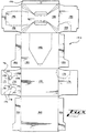
- FIG. 10 therein is illustrated a blank 150 for forming a carton having integral means formed in the carton for removing a divider panel through a wall of the carton.
- the divider panel of the invention may be formed into many different configurations of blanks. A typical blank suitable for use with the invention is shown.
- the blank 150 has a primary rear central panel 160 with opposing end flaps 162, 164; a bottom central panel 170 with opposing end flaps 172, 174; a front central panel 170 with opposing end flaps 182, 184; a top central panel 190 with opposing end flaps 192, 194; and a secondary rear central panel 196.
- the front panel 180 contains a front opening flap 183. Corner can dispenser flaps 175, 195 for the respective top and bottom corners of the carton are formed in an end flap 174 of the bottom central panel 170 and an end flap 195 of the top central panel 190, respectively.
- a side flap 192 of the top central panel 190 contains an end opening flap 193.
- An end flap 172 of the bottom central panel 170 contains a means for removing a divider panel from a carton erected from the blank 150.
- the means for removable of a divider panel is essentially a flap 171 which is able to be affixed to an anchor flap of the divider panel and subsequently torn away from the end flap 172 of an erected carton.
- the tear-away flap 171 is connected to the end flap 172 along cut line 173, tear lines 176 and cut lines 177 which define the punch-out tabs 178.
- the punch-out tabs 178 extend from the tear-away flap along fold lines 179.
- the punch-out tabs 178 are positioned on the end flaps 172 so that when a carton is erected from the blank 150 the punch-out tabs are positioned over the vertical spaces between adjacent cans 10. This feature will be described in more detail below.
- a carton erected from the blank 150 is designed for use with the removable divider panels 20 of the invention discussed above.
- the inner surface of the tear-away flap 171 is affixed to an anchor flap, such as the anchor flap denoted by numeral 24 for panel 20.
- an anchor flap may be attached to the inner surface of the tear-away flap 171
- FIG. 6 illustrates a manner in which an anchor flap may be attached to the inner surface of the tear-away flap 171
- an adhesive 110 is illustrated deposited upon anchor flap 24 for adherence of the associated end flap 58 of the bottom panel to the anchor flap 24.
- the inner surface of the tear-away flap 171 attached to end flap 172 may be attached to the anchor flap of a divider panel in the same manner.
- FIG. 11 therein is illustrated a carton erected from the blank 150.
- FIG. 12 therein is illustrated the carton shown in Fig. 11 constructed from the blank 150 with the end dispensing flap 193 open.
- the top tier of cans 10 has been removed and the tear-away flap 171 has been torn from the end flap 172 to remove the divider panel 152.
- the divider panel 152 is shown partially removed from the carton.
- fingers of an individual may push through the punch-out tabs 178 and then lift upward and outward to tear away the tear-away flap 171 along the tear lines 176.
- the anchor flap at the end of the divider panel opposite the attached tear-away flap may be removed from engagement between the carton end wall and cans or may be torn away from the major panel 22, 122 of the divider panel (as described previously herein) to permit the major panel 22, 122 to be withdrawn from the interior of the carton.
- the major panel 22, 122 and possibly anchor flaps 24, 124, 26, 126 may be manipulated and folded and bent along scored lines (as previously discussed above).
- the panel, 20, 152 may be curled or bowed into an appropriate shape for removal from the carton.
- the panel 150 is curled sufficiently to facilitate withdrawal through the opening in the side of the carton created by removal of the tear-away flap 171.
- the divider panel 20 may also be used to separate containers stackable in arrays similar to the arrays of beverage cans 10 described above. Any containers which are compatible with the features of the divider panel 20 described herein are suitable.
- the divider panel 20 may be used to separate tiers of individual-serving-size milk cartons which cartons have a steeple-shaped top.
- the apertures 37 of the divider panel 20 provide access to the spacing between milk cartons and the tops of the milk cartons.
Landscapes
- Engineering & Computer Science (AREA)
- Mechanical Engineering (AREA)
- Cartons (AREA)
Applications Claiming Priority (1)
| Application Number | Priority Date | Filing Date | Title |
|---|---|---|---|
| EP95914113A EP0812289B1 (fr) | 1995-03-17 | 1995-03-17 | Panneau de separation amovible pour emballage d'articles sur plusieurs couches |
Related Parent Applications (1)
| Application Number | Title | Priority Date | Filing Date |
|---|---|---|---|
| EP95914113A Division EP0812289B1 (fr) | 1995-03-17 | 1995-03-17 | Panneau de separation amovible pour emballage d'articles sur plusieurs couches |
Publications (2)
| Publication Number | Publication Date |
|---|---|
| EP1142797A2 true EP1142797A2 (fr) | 2001-10-10 |
| EP1142797A3 EP1142797A3 (fr) | 2001-10-24 |
Family
ID=8222255
Family Applications (1)
| Application Number | Title | Priority Date | Filing Date |
|---|---|---|---|
| EP01201596A Withdrawn EP1142797A3 (fr) | 1995-03-17 | 1995-03-17 | Panneau de separation amovible pour emballage d'articles sur plusieurs couches |
Country Status (3)
| Country | Link |
|---|---|
| EP (1) | EP1142797A3 (fr) |
| ES (1) | ES2170142T3 (fr) |
| PT (1) | PT812289E (fr) |
Family Cites Families (2)
| Publication number | Priority date | Publication date | Assignee | Title |
|---|---|---|---|---|
| US5482203A (en) * | 1993-09-03 | 1996-01-09 | The Mead Corporation | Handle reinforcement for a carton |
| WO1996029260A1 (fr) * | 1995-03-17 | 1996-09-26 | The Mead Corporation | Panneau de separation renforce pour emballage d'articles a plusieurs niveaux |
-
1995
- 1995-03-17 EP EP01201596A patent/EP1142797A3/fr not_active Withdrawn
- 1995-03-17 ES ES95914113T patent/ES2170142T3/es not_active Expired - Lifetime
- 1995-03-17 PT PT95914113T patent/PT812289E/pt unknown
Also Published As
| Publication number | Publication date |
|---|---|
| EP1142797A3 (fr) | 2001-10-24 |
| PT812289E (pt) | 2002-06-28 |
| ES2170142T3 (es) | 2002-08-01 |
Similar Documents
| Publication | Publication Date | Title |
|---|---|---|
| US5518111A (en) | Removable divider panel for multiple-tier article package | |
| WO1996029260A1 (fr) | Panneau de separation renforce pour emballage d'articles a plusieurs niveaux | |
| EP0715592B1 (fr) | Emballage pour boites comportant une separation en deux rangees | |
| EP1613537B1 (fr) | Carton avec distributeur | |
| US7134551B2 (en) | Dispensing system for double stack carton | |
| US7073665B2 (en) | Dispenser with detachable retention feature | |
| EP0812289B1 (fr) | Panneau de separation amovible pour emballage d'articles sur plusieurs couches | |
| RU2277061C2 (ru) | Картонная коробка с раздаточным устройством | |
| EP1937571B1 (fr) | Cartons avec dispositifs de distribution | |
| EP1740472A1 (fr) | Carton a portion d'angle amovible | |
| AU2005296190A1 (en) | Carton with article opening | |
| AU2005233155A1 (en) | Carton and carton blank with reinforced handle structure | |
| WO2006057697A1 (fr) | Carton pourvu d'une ouverture d'article | |
| US20090057384A1 (en) | Carton for dispensing products and method of using the same | |
| EP2943419A1 (fr) | Emballage doté d'une poignée de transport et découpe de formation de la poignée | |
| EP0428397B1 (fr) | Carton divisible en unités modulaires | |
| AU749694B2 (en) | Removable divider panel for multiple-tier article package | |
| EP1142797A2 (fr) | Panneau de separation amovible pour emballage d'articles sur plusieurs couches | |
| EP1637461B1 (fr) | Emballage en carton comportant un distributeur | |
| NZ300059A (en) | Removable divider panel for multiple-tier article package | |
| MXPA97006668A (en) | Divisor panel removable for packaging of articles in multili | |
| EP1866213B1 (fr) | Carton avec element de distribution |
Legal Events
| Date | Code | Title | Description |
|---|---|---|---|
| PUAI | Public reference made under article 153(3) epc to a published international application that has entered the european phase |
Free format text: ORIGINAL CODE: 0009012 |
|
| PUAL | Search report despatched |
Free format text: ORIGINAL CODE: 0009013 |
|
| 17P | Request for examination filed |
Effective date: 20010430 |
|
| AC | Divisional application: reference to earlier application |
Ref document number: 812289 Country of ref document: EP |
|
| AK | Designated contracting states |
Kind code of ref document: A2 Designated state(s): AT BE CH DE DK ES FR GB GR IE IT LI NL PT SE |
|
| AK | Designated contracting states |
Kind code of ref document: A3 Designated state(s): AT BE CH DE DK ES FR GB GR IE IT LI NL PT SE |
|
| AKX | Designation fees paid |
Free format text: AT BE CH DE DK ES FR GB GR IE IT LI NL PT SE |
|
| 17Q | First examination report despatched |
Effective date: 20030318 |
|
| STAA | Information on the status of an ep patent application or granted ep patent |
Free format text: STATUS: THE APPLICATION HAS BEEN WITHDRAWN |
|
| 18W | Application withdrawn |
Effective date: 20030821 |
|
| RAP1 | Party data changed (applicant data changed or rights of an application transferred) |
Owner name: MEADWESTVACO PACKAGING SYSTEMS LLC |