EP1143094A2 - Cadenas à anses longues - Google Patents
Cadenas à anses longues Download PDFInfo
- Publication number
- EP1143094A2 EP1143094A2 EP01108264A EP01108264A EP1143094A2 EP 1143094 A2 EP1143094 A2 EP 1143094A2 EP 01108264 A EP01108264 A EP 01108264A EP 01108264 A EP01108264 A EP 01108264A EP 1143094 A2 EP1143094 A2 EP 1143094A2
- Authority
- EP
- European Patent Office
- Prior art keywords
- lock according
- tubular housing
- long shackle
- locking
- long
- Prior art date
- Legal status (The legal status is an assumption and is not a legal conclusion. Google has not performed a legal analysis and makes no representation as to the accuracy of the status listed.)
- Granted
Links
- 230000007246 mechanism Effects 0.000 claims abstract description 28
- 230000003014 reinforcing effect Effects 0.000 claims description 13
- 230000001681 protective effect Effects 0.000 claims description 12
- 239000000463 material Substances 0.000 claims description 8
- 230000000149 penetrating effect Effects 0.000 claims description 7
- 230000000284 resting effect Effects 0.000 claims 1
- 238000007747 plating Methods 0.000 abstract 3
- 239000002184 metal Substances 0.000 description 6
- 229910052751 metal Inorganic materials 0.000 description 6
- 230000007480 spreading Effects 0.000 description 5
- 238000003892 spreading Methods 0.000 description 5
- 239000011324 bead Substances 0.000 description 2
- 230000006378 damage Effects 0.000 description 2
- 238000004519 manufacturing process Methods 0.000 description 2
- 229910001229 Pot metal Inorganic materials 0.000 description 1
- 229910000831 Steel Inorganic materials 0.000 description 1
- 230000000712 assembly Effects 0.000 description 1
- 238000000429 assembly Methods 0.000 description 1
- 239000000919 ceramic Substances 0.000 description 1
- 238000005253 cladding Methods 0.000 description 1
- 238000005352 clarification Methods 0.000 description 1
- 238000003780 insertion Methods 0.000 description 1
- 230000037431 insertion Effects 0.000 description 1
- 230000009467 reduction Effects 0.000 description 1
- 230000002787 reinforcement Effects 0.000 description 1
- 239000010959 steel Substances 0.000 description 1
- 230000007704 transition Effects 0.000 description 1
- 238000003466 welding Methods 0.000 description 1
Images

Classifications
-
- E—FIXED CONSTRUCTIONS
- E05—LOCKS; KEYS; WINDOW OR DOOR FITTINGS; SAFES
- E05B—LOCKS; ACCESSORIES THEREFOR; HANDCUFFS
- E05B67/00—Padlocks; Details thereof
- E05B67/06—Shackles; Arrangement of the shackle
- E05B67/22—Padlocks with sliding shackles, with or without rotary or pivotal movement
- E05B67/24—Padlocks with sliding shackles, with or without rotary or pivotal movement with built- in cylinder locks
-
- E—FIXED CONSTRUCTIONS
- E05—LOCKS; KEYS; WINDOW OR DOOR FITTINGS; SAFES
- E05B—LOCKS; ACCESSORIES THEREFOR; HANDCUFFS
- E05B67/00—Padlocks; Details thereof
- E05B67/02—Cases
- E05B67/04—Armoured cases
-
- E—FIXED CONSTRUCTIONS
- E05—LOCKS; KEYS; WINDOW OR DOOR FITTINGS; SAFES
- E05B—LOCKS; ACCESSORIES THEREFOR; HANDCUFFS
- E05B67/00—Padlocks; Details thereof
- E05B67/06—Shackles; Arrangement of the shackle
- E05B67/063—Padlocks with removable shackles
Definitions
- the invention relates to a long shackle lock with a an elongated lock body immersed at both ends Shackle, with one arranged in the lock body Locking mechanism for moving locking means in one arranged at the free ends of the bracket Leg sections locking or unlocking position, with a substantially tubular housing for Inclusion of the locking means and the locking mechanism and arranged on the end sides inside the housing, U-shaped armor.
- Such a long shackle lock is, for example, from the DE 43 22 989 C2 known.
- the tubular housing will by welding a U-shaped profile piece to a Base plate made.
- the square tube has the holding function for the parts of the locking mechanism the functions of the radial Armor of the lock body and in the closed position the long shackle lock securing the shackle ends against spreading.
- Another one surrounding the lock body outer cover housing is usually made of plastic manufactured and serves the long shackle lock to give a pleasing look.
- This long shackle lock has the disadvantage that security against attempts to break open only through the tubular Housing and through the on the head sides through the Cover housing easily accessible parts of the lock mechanism must be guaranteed. Therefore, the tubular Housing must be very thick-walled so that Recesses for the leg sections of the bracket in tubular housing an attempt to expand the long bracket withstand. Furthermore, those accessible at the top must be accessible Parts of the lock mechanism are accordingly stable be formed.
- these parts exist because of their complicated shape, on the other hand, the requirement to manufacture them from easily processable material. Such material is then usually very soft or im Case of die-cast zinc is brittle and therefore when trying to attack easy to destroy. The pinning of the parts can usually be easily overcome and the parts pulled apart become.
- the invention is based on the problem of a long shackle lock of the type mentioned at the beginning, that it is particularly easy to assemble and in particular expansion forces acting in the longitudinal direction of the lock body supported as reliably as possible.
- the lock body has a closed one Armor, so the components of the locking mechanism and the locking means also reliably in the event of an attempt to attack from its end sides by the U-shaped armor are protected. Because the U-shaped Armor interconnected via the bracing means are, they contribute to increasing the stability of the Lock body against spreading.
- the tubular This supports the housing in particular by spreading it out longitudinal forces of the bracket are particularly reliable from.
- the positive connection is within the tubular housing arranged and thus for attack attempts inaccessible.
- the long shackle lock according to the invention can in the simplest case with the U-shaped Armor, the bracing and the Pre-assemble the locking mechanism as a structural unit and from an open end into the tubular housing introduce.
- the long shackle lock according to the invention easy to assemble.
- the tubular housing of the long shackle lock according to the invention made of a thin-walled material are known as the housing of the well-known long shackle lock.
- This contributes to a particularly low weight and to low Material costs of the long shackle lock according to the invention at.
- the light weight of the invention Long shackle lock simplifies carrying it, for example on a two-wheeler.
- the bracket of the invention Long shackle lock can be used as in the known Long shackle lock designed rigid or formed by a cable his.
- Long shackle lock will be the U-shaped Armor reliably held when the tubular Housing for holding the positive connection of the bracing means is designed with the U-shaped armor. This allows the internal components of the invention Do not disassemble the long shackle lock until that tubular housing is completely disassembled. The complete one Disassembly of the tubular housing, however by guiding the leg sections to be locked of the bracket largely through the tubular housing prevented.
- the bracing means are designed according to another advantageous development of the invention is particularly cost-effective, if they have a protective plate. Farther the bracing means can be particularly special easy to assemble.
- the lock body can be advantageous according to another Development of the invention is particularly small and compact be designed when the legs of the U-shaped armor enclosing the leg sections of the bracket laterally are aligned.
- leg sections into the lock body is designed according to another advantageous development the invention particularly simple if the leg sections at their free ends to a conical one Section have subsequent pins. Furthermore, the pin can be in the recess of the bend penetrate the U-shaped armor. Through the Cross-section reduction through the conical section the bend on the spigot can be wide and therefore very large be stable.
- the tubular carries the housing the invention when in the area of the ends of the tubular housing within the U-shaped armor a reinforcing part is arranged.
- the long shackle lock according to the invention requires particularly Few components to be assembled if the pins are at right angles to the Aligned axis of the leg portions of the bracket and in the third of the most distant from the protective plate Lock body are arranged. Through this design the locking means need only one Protection plate for connecting the U-shaped armor.
- Long shackle locks are the tubular housing reliably connected to the U-shaped armor, when the pins connect the tubular housing arranged in pairs, facing each other are and if a cross plate is arranged between the pins is. With this design, the pins not be pushed out of the tubular housing. This contributes to a further increase in the security of the invention Long shackle lock against destruction at.
- a forwarding of one of the leg sections transferred to the locking mechanism in the lock body Forces to locking means of the other leg section is according to another advantageous development the invention reliably prevented when a Lock cylinder of the locking mechanism in the protective plate is stored.
- the leg sections individually and therefore essentially independently held in the lock body from each other.
- the lock body sets according to another advantageous one Further development of the invention an attempted severing a particularly high stability when the tubular Housing and the U-shaped armor made of different Materials are made.
- the tubular housing and the U-shaped Armor when between the tubular housing and the U-shaped Armor is arranged a layer and that the Layer is made of a different material than that tubular housing.
- the one made of sheet steel This layer can be tubular, for example Ceramic included.
- the lock body is too easy to assemble Pre-assemble handling assemblies if the U-shaped Armor centering for a locking mechanism and have locking means guiding holding part.
- the long shackle lock according to the invention helps if the holding part is made of plastic.
- the locking mechanism or the locking means a spring element for prestressing in a intended position.
- the support of the spring element on a fixed component is constructive particularly easy if the protective plate has a tab for Support one for pretensioning the locking mechanism and / or the locking means designed spring element having.
- the locking means are advantageous according to another Further development of the invention is particularly constructive simply built if one of the locking mechanism movable and designed to lock the bracket Locking bolt of the locking means at least one has elongated frame.
- the frame is preferably self-contained.
- the lock body is designed according to another advantageous one Development of the invention is particularly compact, if the spring element for biasing the locking means arranged within the frame of the locking bolt is.
- Long shackle lock helps when the frame the locking bolt is made of plastic if the for locking with the leg sections of the bracket provided ends of the locking bolt each have a reinforcing element and if the reinforcing elements have larger dimensions than for the introduction of the leg sections the bracket provided in the tubular housing Recesses.
- the lock body of the long shackle lock it carries at if the area having the reinforcing element of the locking bolt directly on the tubular housing is present.
- the lock body sets with tensile forces acting on the shackle a particularly high resistance if the locking bolt is fork-shaped, the leg section is at least partially encompassing the sides. As a result, the locking bolt on the tubular Support the housing. Therefore, no component will bend claimed.
- the reinforcing element is particularly inexpensive and has a large contact surface on the Leg section when the reinforcing element as Role is formed.
- the spring element could, for example, immediately support on the plastic frame.
- a Damage to the frame can be caused by the spring element however according to another advantageous development simply avoid the invention if in the context of Locking bolt arranged a support block for the spring element is.
- Figure 1 shows a long shackle lock with a lock body 1 and a bracket locked in the lock body 1 2.
- the lock body 1 has a partially cut open shown tubular housing 3 and an inner armor 4.
- the inner armor 4 has a stamped and bent sheet metal protective plate 5.
- On the ends of the lock body 1 is a U-shaped armor 6 arranged while the protective plate 5 essentially is just designed.
- the protective plate 5 and the U-shaped armor 6 have in their contiguous areas each interlocking Hooks 7, 8 and recesses 9, 10 to their positive Connection on.
- the tubular housing 3 is as Square tube formed and over the inner armor 4 pushed.
- the tubular housing 3 is via pressed pins 12, 12 'connected to the U-shaped armor.
- the pencils 12, 12 ' are not passed through the lock body 1, instead they bump into one on the opposite side of the inner armor 4 arranged Stop or at a not shown, in the Holding part 11 arranged cross plate. Let her through the pins 12, 12 'do not come out of the Press out lock body 1.
- the lock body 1 is enclosed by a plastic cover housing 13. This cover housing 13 is used for cladding of the lock body 1.
- the U-shaped armor 6 has centering means 14 for connection to the holding part 11.
- the Bracket 2 has two through recesses 15 of the tubular Housing 3 in the inner armor 4 penetrating leg sections 16, 16 '. These leg sections 16, 16 ' are in the locked state of the long shackle lock positively held within the inner armor 4.
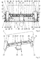
- FIG 2 shows a sectional view through the long shackle lock from Figure 1 along the line II - II that the holding part 11 guides 17 - 19 for locking means 20, 21 and a locking mechanism 22.
- the Locking means 20, 21 each have an in to the Leg sections 16, 16 'of the bracket 2 arranged Recesses 23, 24 penetrating locking bolts 25, 26.
- One end of the locking bar 25, 26 lies against one an approximately oval cross-section driver 27 of the locking mechanism 22.
- the driver 27 leaves itself when unlocking or locking the long shackle lock by means of a locking cylinder 28 of the Turn the locking mechanism 22 of the insertable key 42.
- the locking bolts 25, 26 each have an elongated Frame 29, 30 in which a spring element 31, 32 is arranged.
- the protective plate 5 has a bearing bore 33 for a bearing pin 43 of the locking cylinder 28 and angled downwards into the frames 29, 30 penetrating tabs 34, 35 for supporting the spring elements 31, 32.
- the frame 29, 30 there are also support walls 36, 37 arranged for the spring elements 31, 32.
- the recesses 23, 24 of the leg sections 16, 16 ' penetrating ends of the locking bolts 25, 26 have reinforcing elements 38, 39 with larger dimensions than that Recesses 15, 15 'in the housing 3 and the armor 4th on.
- the frames 29, 30 and the holding part 11 are made Made of plastic.
- Figure 2 also shows that between the leg sections 16, 16 'of the bracket 2 and the U-shaped armor 6 reinforcement parts 40, 41 arranged are.
- the leg sections of the bracket point each adjoining a conical taper Pin 44, 44 'on. These pins 44, 44 'penetrate Recesses 45, 45 'of the inner armor 4.
- the Recesses 45, 45 ' are in bends 46, 46' of the U-shaped Armor 6, 6 'arranged. Furthermore, the U-shaped Armor 6, 6 'on the leg sections 16, 16 'adjacent projections 47, 47'.
- the locking means shown in FIG. 2 are for clarification 20, 21, the locking mechanism 22 and the leg sections 16, 16 'of the bracket 2 in perspective shown in Figure 3.
- the one in the drawing The long-latch lock shown are the locking bolts 25, 26 by means of the spring elements 31, 32 in the closed position biased.
- the driver 27 Prevented in the position shown the driver 27 a movement of the locking latch 25, 26th from the recesses 23, 24 of the leg sections 16, 16 'of the shackle 2. This locks the long shackle lock.
- Longitudinal forces acting on the locking bolts 25, 26 are from the bearing bore shown in Figure 2 33 penetrating bearing pin 43 supported.
- the driver 27th rotated by 90 ° and thus a movement of the locking bolts 25, 26 released from the recesses 23, 24 of the bracket 2.
- the bracket 2 can thus be from that shown in Figure 2 Pull out lock body 1.
- the bracket 2 can then only again when the long-handle lock is unlocked be connected to the lock body 1.
- the locking mechanism 22 and the locking means 20, 21 can but also be designed such that the bracket 2 in the locked State is connected to the lock body 1.
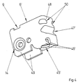
- FIG 4 shows in perspective one of the U-shaped armor 6 'from Figure 2.
- the U-shaped armor 6' is from stamped and bent sheet metal and has one Bottom 48 with adjoining legs 49. Clear can be seen that the recess for the pin of the Bracket on two opposing bends 46 'adjacent.
- the projection 47 ' is as elongated, in which Bottom 48 arranged bead formed. Of course the projection 47 'can also be of a frustoconical shape Imprint formed. In the transition areas the bottom 48 to the legs 49 are reinforcing beads 50 arranged.
Landscapes
- Hooks, Suction Cups, And Attachment By Adhesive Means (AREA)
- Clamps And Clips (AREA)
- Lock And Its Accessories (AREA)
Applications Claiming Priority (2)
| Application Number | Priority Date | Filing Date | Title |
|---|---|---|---|
| DE10017118 | 2000-04-06 | ||
| DE10017118A DE10017118A1 (de) | 2000-04-06 | 2000-04-06 | Langbügelschloß |
Publications (3)
| Publication Number | Publication Date |
|---|---|
| EP1143094A2 true EP1143094A2 (fr) | 2001-10-10 |
| EP1143094A3 EP1143094A3 (fr) | 2003-06-04 |
| EP1143094B1 EP1143094B1 (fr) | 2005-01-26 |
Family
ID=7637784
Family Applications (1)
| Application Number | Title | Priority Date | Filing Date |
|---|---|---|---|
| EP01108264A Expired - Lifetime EP1143094B1 (fr) | 2000-04-06 | 2001-04-02 | Cadenas à anses longues |
Country Status (2)
| Country | Link |
|---|---|
| EP (1) | EP1143094B1 (fr) |
| DE (2) | DE10017118A1 (fr) |
Cited By (3)
| Publication number | Priority date | Publication date | Assignee | Title |
|---|---|---|---|---|
| WO2004041629A3 (fr) * | 2002-11-04 | 2004-08-12 | Bremicker Soehne Kg A | Cadenas a deux-roues |
| RU2283406C1 (ru) * | 2004-12-21 | 2006-09-10 | Михаил Юрьевич Рылеев | Защитная броневая накладка рылеева для цилиндрового замка |
| RU2283407C1 (ru) * | 2004-12-21 | 2006-09-10 | Михаил Юрьевич Рылеев | Защитная броневая накладка рылеева для цилиндрового замка |
Citations (1)
| Publication number | Priority date | Publication date | Assignee | Title |
|---|---|---|---|---|
| DE4322989C2 (de) | 1993-07-09 | 1996-10-10 | Winkhaus Fa August | Bügelschloß, insbesondere Langbügelschloß |
Family Cites Families (3)
| Publication number | Priority date | Publication date | Assignee | Title |
|---|---|---|---|---|
| DE3815584C1 (fr) * | 1988-05-06 | 1989-08-10 | Aug. Winkhaus Gmbh & Co Kg, 4404 Telgte, De | |
| US4949564A (en) * | 1989-11-13 | 1990-08-21 | Nabob Ltd. | Padlock with a hard shell casing for receiving a cylinder lock unit |
| GB9010959D0 (en) * | 1990-05-09 | 1990-07-04 | Squire Henry & Sons | Lock assembly |
-
2000
- 2000-04-06 DE DE10017118A patent/DE10017118A1/de not_active Withdrawn
-
2001
- 2001-04-02 EP EP01108264A patent/EP1143094B1/fr not_active Expired - Lifetime
- 2001-04-02 DE DE50105162T patent/DE50105162D1/de not_active Expired - Lifetime
Patent Citations (1)
| Publication number | Priority date | Publication date | Assignee | Title |
|---|---|---|---|---|
| DE4322989C2 (de) | 1993-07-09 | 1996-10-10 | Winkhaus Fa August | Bügelschloß, insbesondere Langbügelschloß |
Cited By (3)
| Publication number | Priority date | Publication date | Assignee | Title |
|---|---|---|---|---|
| WO2004041629A3 (fr) * | 2002-11-04 | 2004-08-12 | Bremicker Soehne Kg A | Cadenas a deux-roues |
| RU2283406C1 (ru) * | 2004-12-21 | 2006-09-10 | Михаил Юрьевич Рылеев | Защитная броневая накладка рылеева для цилиндрового замка |
| RU2283407C1 (ru) * | 2004-12-21 | 2006-09-10 | Михаил Юрьевич Рылеев | Защитная броневая накладка рылеева для цилиндрового замка |
Also Published As
| Publication number | Publication date |
|---|---|
| DE50105162D1 (de) | 2005-03-03 |
| EP1143094A3 (fr) | 2003-06-04 |
| EP1143094B1 (fr) | 2005-01-26 |
| DE10017118A1 (de) | 2001-10-11 |
Similar Documents
| Publication | Publication Date | Title |
|---|---|---|
| EP2020474B1 (fr) | Serrure | |
| EP2019178B1 (fr) | Serrure à barres articulées | |
| DE69925591T2 (de) | Bügelschloss mit auswechselbarem Schliessmechanismus | |
| EP2267256B1 (fr) | Cadenas | |
| EP0369107A2 (fr) | Serrure cylindrique | |
| EP2266868B1 (fr) | Cadenas en U | |
| EP3153648B1 (fr) | Cadenas | |
| EP3566933A1 (fr) | Système de fermeture de cadre pour un deux roues | |
| DE69830813T2 (de) | Kraftwagentürscharnier | |
| EP0438654B1 (fr) | Serrure à double cylindre | |
| EP1802831B1 (fr) | Cylindre de fermeture modulaire | |
| DE19853712B4 (de) | Transport- und Verlegeanker mit querverstrebten Längsverankerungsschenkeln | |
| EP1743992A2 (fr) | Dispositif de montage d'une clôture avec poteau de clôture et support | |
| DE10333211B4 (de) | Schließzylinder | |
| WO2001073302A2 (fr) | Element tubulaire | |
| EP1143094B1 (fr) | Cadenas à anses longues | |
| DE102022111846A1 (de) | Bügelschloss mit Aufschweißpanzerung | |
| DE29808432U1 (de) | Steckzylinderschloß, insbesondere zur Verwendung an Schutzvorrichtungen und Fallen für Spiel- und Warenautomaten, an Gitterrolltoren, an beweglichen Schutzgittern o.dgl. | |
| EP0683091B1 (fr) | Serrure pour frein à disque | |
| DE10318913B4 (de) | Schließzylinder | |
| EP0808970B1 (fr) | Serrure à cylindre | |
| DE10317448A1 (de) | Kupplungseinrichtung an Doppelschließzylinder | |
| EP1249568A2 (fr) | Serrure à chaine ou à cable | |
| EP1760229B1 (fr) | Cylindre de fermeture, notamment cylindres profilés, pour un dispositif de verrouillage tel que une serrure de porte | |
| EP3741935B1 (fr) | Verrou d'aiguille à articulation |
Legal Events
| Date | Code | Title | Description |
|---|---|---|---|
| PUAI | Public reference made under article 153(3) epc to a published international application that has entered the european phase |
Free format text: ORIGINAL CODE: 0009012 |
|
| AK | Designated contracting states |
Kind code of ref document: A2 Designated state(s): AT BE CH CY DE DK ES FI FR GB GR IE IT LI LU MC NL PT SE TR |
|
| AX | Request for extension of the european patent |
Free format text: AL;LT;LV;MK;RO;SI |
|
| PUAL | Search report despatched |
Free format text: ORIGINAL CODE: 0009013 |
|
| AK | Designated contracting states |
Designated state(s): AT BE CH CY DE DK ES FI FR GB GR IE IT LI LU MC NL PT SE TR |
|
| AX | Request for extension of the european patent |
Extension state: AL LT LV MK RO SI |
|
| RIC1 | Information provided on ipc code assigned before grant |
Ipc: 7E 05B 67/06 B Ipc: 7E 05B 67/04 A Ipc: 7E 05B 67/24 B |
|
| 17P | Request for examination filed |
Effective date: 20030430 |
|
| 17Q | First examination report despatched |
Effective date: 20031111 |
|
| AKX | Designation fees paid |
Designated state(s): DE DK NL SE |
|
| GRAP | Despatch of communication of intention to grant a patent |
Free format text: ORIGINAL CODE: EPIDOSNIGR1 |
|
| GRAS | Grant fee paid |
Free format text: ORIGINAL CODE: EPIDOSNIGR3 |
|
| GRAA | (expected) grant |
Free format text: ORIGINAL CODE: 0009210 |
|
| AK | Designated contracting states |
Kind code of ref document: B1 Designated state(s): DE DK NL SE |
|
| REG | Reference to a national code |
Ref country code: IE Ref legal event code: FG4D Free format text: GERMAN |
|
| REF | Corresponds to: |
Ref document number: 50105162 Country of ref document: DE Date of ref document: 20050303 Kind code of ref document: P |
|
| PG25 | Lapsed in a contracting state [announced via postgrant information from national office to epo] |
Ref country code: DK Free format text: LAPSE BECAUSE OF FAILURE TO SUBMIT A TRANSLATION OF THE DESCRIPTION OR TO PAY THE FEE WITHIN THE PRESCRIBED TIME-LIMIT Effective date: 20050426 |
|
| REG | Reference to a national code |
Ref country code: SE Ref legal event code: TRGR |
|
| PLBE | No opposition filed within time limit |
Free format text: ORIGINAL CODE: 0009261 |
|
| STAA | Information on the status of an ep patent application or granted ep patent |
Free format text: STATUS: NO OPPOSITION FILED WITHIN TIME LIMIT |
|
| 26N | No opposition filed |
Effective date: 20051027 |
|
| REG | Reference to a national code |
Ref country code: DE Ref legal event code: R082 Ref document number: 50105162 Country of ref document: DE Representative=s name: SWEN HENTRICH, DE |
|
| REG | Reference to a national code |
Ref country code: DE Ref legal event code: R081 Ref document number: 50105162 Country of ref document: DE Owner name: TRELOCK GMBH, DE Free format text: FORMER OWNER: TRELOCK GMBH, 48301 NOTTULN, DE Effective date: 20120127 Ref country code: DE Ref legal event code: R082 Ref document number: 50105162 Country of ref document: DE Representative=s name: HENTRICH, SWEN, DIPL.-PHYS. DR.RER.NAT., DE Effective date: 20120127 |
|
| PGFP | Annual fee paid to national office [announced via postgrant information from national office to epo] |
Ref country code: NL Payment date: 20120503 Year of fee payment: 12 Ref country code: DE Payment date: 20120411 Year of fee payment: 12 |
|
| PGFP | Annual fee paid to national office [announced via postgrant information from national office to epo] |
Ref country code: SE Payment date: 20120423 Year of fee payment: 12 |
|
| REG | Reference to a national code |
Ref country code: NL Ref legal event code: V1 Effective date: 20131101 |
|
| REG | Reference to a national code |
Ref country code: SE Ref legal event code: EUG |
|
| PG25 | Lapsed in a contracting state [announced via postgrant information from national office to epo] |
Ref country code: DE Free format text: LAPSE BECAUSE OF NON-PAYMENT OF DUE FEES Effective date: 20131101 Ref country code: SE Free format text: LAPSE BECAUSE OF NON-PAYMENT OF DUE FEES Effective date: 20130403 |
|
| REG | Reference to a national code |
Ref country code: DE Ref legal event code: R119 Ref document number: 50105162 Country of ref document: DE Effective date: 20131101 |
|
| PG25 | Lapsed in a contracting state [announced via postgrant information from national office to epo] |
Ref country code: NL Free format text: LAPSE BECAUSE OF NON-PAYMENT OF DUE FEES Effective date: 20131101 |