EP1143128A2 - Kraftstoffzufuhrsystem - Google Patents
Kraftstoffzufuhrsystem Download PDFInfo
- Publication number
- EP1143128A2 EP1143128A2 EP01302626A EP01302626A EP1143128A2 EP 1143128 A2 EP1143128 A2 EP 1143128A2 EP 01302626 A EP01302626 A EP 01302626A EP 01302626 A EP01302626 A EP 01302626A EP 1143128 A2 EP1143128 A2 EP 1143128A2
- Authority
- EP
- European Patent Office
- Prior art keywords
- fluid
- pressure
- inlet
- pump
- bypass means
- Prior art date
- Legal status (The legal status is an assumption and is not a legal conclusion. Google has not performed a legal analysis and makes no representation as to the accuracy of the status listed.)
- Withdrawn
Links
- 239000000446 fuel Substances 0.000 title claims abstract description 42
- 239000012530 fluid Substances 0.000 claims description 69
- 238000000034 method Methods 0.000 claims description 5
- 238000012544 monitoring process Methods 0.000 claims description 2
- 239000002828 fuel tank Substances 0.000 description 3
- 235000003642 hunger Nutrition 0.000 description 3
- 230000037452 priming Effects 0.000 description 3
- 230000037351 starvation Effects 0.000 description 3
- 230000005494 condensation Effects 0.000 description 2
- 238000009833 condensation Methods 0.000 description 2
- 230000005764 inhibitory process Effects 0.000 description 1
- 230000004044 response Effects 0.000 description 1
Images
Classifications
-
- F—MECHANICAL ENGINEERING; LIGHTING; HEATING; WEAPONS; BLASTING
- F02—COMBUSTION ENGINES; HOT-GAS OR COMBUSTION-PRODUCT ENGINE PLANTS
- F02C—GAS-TURBINE PLANTS; AIR INTAKES FOR JET-PROPULSION PLANTS; CONTROLLING FUEL SUPPLY IN AIR-BREATHING JET-PROPULSION PLANTS
- F02C7/00—Features, components parts, details or accessories, not provided for in, or of interest apart form groups F02C1/00 - F02C6/00; Air intakes for jet-propulsion plants
- F02C7/26—Starting; Ignition
- F02C7/262—Restarting after flame-out
-
- F—MECHANICAL ENGINEERING; LIGHTING; HEATING; WEAPONS; BLASTING
- F02—COMBUSTION ENGINES; HOT-GAS OR COMBUSTION-PRODUCT ENGINE PLANTS
- F02C—GAS-TURBINE PLANTS; AIR INTAKES FOR JET-PROPULSION PLANTS; CONTROLLING FUEL SUPPLY IN AIR-BREATHING JET-PROPULSION PLANTS
- F02C7/00—Features, components parts, details or accessories, not provided for in, or of interest apart form groups F02C1/00 - F02C6/00; Air intakes for jet-propulsion plants
- F02C7/22—Fuel supply systems
- F02C7/232—Fuel valves; Draining valves or systems
-
- F—MECHANICAL ENGINEERING; LIGHTING; HEATING; WEAPONS; BLASTING
- F02—COMBUSTION ENGINES; HOT-GAS OR COMBUSTION-PRODUCT ENGINE PLANTS
- F02C—GAS-TURBINE PLANTS; AIR INTAKES FOR JET-PROPULSION PLANTS; CONTROLLING FUEL SUPPLY IN AIR-BREATHING JET-PROPULSION PLANTS
- F02C7/00—Features, components parts, details or accessories, not provided for in, or of interest apart form groups F02C1/00 - F02C6/00; Air intakes for jet-propulsion plants
- F02C7/22—Fuel supply systems
- F02C7/236—Fuel delivery systems comprising two or more pumps
-
- F—MECHANICAL ENGINEERING; LIGHTING; HEATING; WEAPONS; BLASTING
- F02—COMBUSTION ENGINES; HOT-GAS OR COMBUSTION-PRODUCT ENGINE PLANTS
- F02C—GAS-TURBINE PLANTS; AIR INTAKES FOR JET-PROPULSION PLANTS; CONTROLLING FUEL SUPPLY IN AIR-BREATHING JET-PROPULSION PLANTS
- F02C9/00—Controlling gas-turbine plants; Controlling fuel supply in air- breathing jet-propulsion plants
- F02C9/26—Control of fuel supply
- F02C9/36—Control of fuel supply characterised by returning of fuel to sump
-
- F—MECHANICAL ENGINEERING; LIGHTING; HEATING; WEAPONS; BLASTING
- F05—INDEXING SCHEMES RELATING TO ENGINES OR PUMPS IN VARIOUS SUBCLASSES OF CLASSES F01-F04
- F05D—INDEXING SCHEME FOR ASPECTS RELATING TO NON-POSITIVE-DISPLACEMENT MACHINES OR ENGINES, GAS-TURBINES OR JET-PROPULSION PLANTS
- F05D2270/00—Control
- F05D2270/01—Purpose of the control system
- F05D2270/09—Purpose of the control system to cope with emergencies
- F05D2270/092—Purpose of the control system to cope with emergencies in particular blow-out and relight
-
- F—MECHANICAL ENGINEERING; LIGHTING; HEATING; WEAPONS; BLASTING
- F05—INDEXING SCHEMES RELATING TO ENGINES OR PUMPS IN VARIOUS SUBCLASSES OF CLASSES F01-F04
- F05D—INDEXING SCHEME FOR ASPECTS RELATING TO NON-POSITIVE-DISPLACEMENT MACHINES OR ENGINES, GAS-TURBINES OR JET-PROPULSION PLANTS
- F05D2270/00—Control
- F05D2270/30—Control parameters, e.g. input parameters
- F05D2270/301—Pressure
Definitions
- the present invention relates to fluid apparatus and in particular to fluid apparatus for use in the fuel system of a gas turbine engine.
- the primary inhibition to priming is the potential vapour lock in the engine fuel heat exchanger and the high-pressure fuel pump. Priming can only take place if the local pressure is increased or the heat exchanger is cooled to allow condensation of the fuel to occur. It is known to achieve condensation of the fuel by reducing the aircraft altitude to increase the system pressure and/or providing an additional heat exchanger.
- the present invention seeks to provide a fluid apparatus and method of operating the same that allows a fluid pump to be primed and started without the need to change the aircraft altitude or the need for an additional heat exchanger.
- a fluid apparatus comprises a fluid pump having an inlet and an outlet to permit a flow of fluid therethrough and bypass means connected adjacent the inlet to the fluid pump, whereby in normal operation the bypass means is closed so that all the fluid passes through the fluid pump, however when the fluid pressure at the inlet to the fluid pump drops below a predetermined level the bypass means opens to allow the fluid to bypass the fluid pump, the bypass means closing to return the fluid flow to the inlet of the fluid pump when the fluid pressure increases above the predetermined level.
- the bypass means incorporates a vent valve which vents any vapour entrained within the fluid flow passing therethrough.
- the vent valve is pressure responsive and vapour is vented to a drain tank.
- the bypass means is electrically operated and may be a solenoid operated valve.
- a heat exchanger may be provided adjacent the inlet to the fluid pump the bypass means operating to allow the fluid to bypass the heat exchanger when the fluid pressure is below a predetermined level.
- the fluid may be fuel and the apparatus is suitable for use in the fuel system of a gas turbine engine.
- a further aspect of the present invention is a method of operating a fluid apparatus which comprises a fluid pump having an inlet and an outlet and bypass means adjacent the inlet to the fluid pump, the method comprising the steps of monitoring the pressure of the fluid at the inlet to the fluid pump, comparing the pressure of the fluid at the inlet to the fluid pump with a predetermined value, opening the bypass means if the pressure of the fluid at the inlet to the pump is below the predetermined value and closing the bypass means when the fluid pressure increases above the predetermined value.
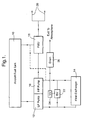
- Figure 1 is a diagrammatic view of a fuel system in accordance with the present invention.
- Figure 2 is an enlarged cross-sectional view of part of the fuel system shown in figure 1.
- a low-pressure pump 12 provides fuel from aircraft fuel tank 10 to a heat exchanger 14. Fuel passes through the heat exchanger 14 to the high-pressure pump 16, which provides fuel to the fuel-metering unit 18. The fuel-metering unit 18 provides the required flow of fuel to the engine burners 20 to meet the engine demands. The fuel metering unit 18 spills any fuel not required by the engine back to the aircraft fuel tank 10 or to the inlet of the high pressure pump 16 (shown by the dotted line in figure 1).
- the distribution of the fuel in the system is controlled by the engine electronic control (not shown).
- the engine electronic control recognises that the engine is windmilling and has a low fuel inlet pressure it opens a bypass 22 and vent valve 24.
- the bypass and vent valves 22 and 24 are connected in parallel with the normal flow path between the low and high-pressure fuel pumps, 12 and 16 respectively. Gas is vented out of the fuel system and gas and fuel bypass the heat exchanger 14 between the low and high-pressure pumps 12 and 16, thus avoiding the need to overcome vapour locks between the two pumps.
- the vent valve 24 passes gas out of the fuel system to a drain tank 26, or other disposal means (not shown), and then closes to prevent the escape of fuel as the high-pressure pump 16 primes.
- the two valves 22 and 24 could by separate units however in the preferred embodiment shown in figure 2 the two valves 22 and 24 are located in the same housing and are controlled by the engine electronic control (not shown) . Both of the valves 22 and 24 have position indicator switches 30 and 32, which tell the engine electronic, control the status of the valves 22 and 24 i.e. open or closed. The engine electronic control checks the status of the valves 22 and 24 as indicated by switches 30 and 32 respectively against the commanded position.
- the engine electronic control electrically powers solenoid 34.
- the solenoid 34 moves the plunger 36 to connect together ports A and B which control the bypass valve 22 and ports C and D which control the vent valve 24.
- ports A and B are at the same pressure the bypass valve 22 opens and vapour passes through the bypass valve 22 to the vent valve 24.
- the loss of high pressure at the ports C and D causes the spring 38 in the vent valve 24 to open the valve.
- the vent valve 24 opens the gas passes through the vent valve 24, to the drain tank 26 via the line 40.
- the line 40 out of the vent valve 24 is restricted so that once all the fuel vapour/gas has passed out of the vent valve 24 the fuel pressure is sufficient to automatically close the vent valve.
- the solenoid 34 is powered open by the engine electronic control until the engine reaches idle speed. At this speed the solenoid 34 is powered to close the bypass valve 22 returning the system to its normal operating mode.
- the fuel system in accordance with the present invention allows the fuel pump to be primed and restarted after fuel starvation without having to change the aircraft altitude or provide an additional heat exchanger.
- the present invention has been described with reference to a fuel system of a gas turbine engine however it will be appreciated that it is applicable to any fluid system where a fluid pump has to be restarted following a vapour lock.
- valves 22 and 24 which are electrically controlled
- the valves 22 and 24 may be pressure responsive.
- the valves 22 and 24 operating in response to changes in system pressure and fluid flow conditions.
Landscapes
- Engineering & Computer Science (AREA)
- Chemical & Material Sciences (AREA)
- Combustion & Propulsion (AREA)
- Mechanical Engineering (AREA)
- General Engineering & Computer Science (AREA)
- Control Of Positive-Displacement Pumps (AREA)
- Control Of Fluid Pressure (AREA)
Applications Claiming Priority (2)
| Application Number | Priority Date | Filing Date | Title |
|---|---|---|---|
| GBGB0008470.7A GB0008470D0 (en) | 2000-04-07 | 2000-04-07 | Fluid apparatus and method of using the same |
| GB0008470 | 2000-04-07 |
Publications (1)
| Publication Number | Publication Date |
|---|---|
| EP1143128A2 true EP1143128A2 (de) | 2001-10-10 |
Family
ID=9889349
Family Applications (1)
| Application Number | Title | Priority Date | Filing Date |
|---|---|---|---|
| EP01302626A Withdrawn EP1143128A2 (de) | 2000-04-07 | 2001-03-21 | Kraftstoffzufuhrsystem |
Country Status (3)
| Country | Link |
|---|---|
| US (1) | US20010027641A1 (de) |
| EP (1) | EP1143128A2 (de) |
| GB (1) | GB0008470D0 (de) |
Cited By (4)
| Publication number | Priority date | Publication date | Assignee | Title |
|---|---|---|---|---|
| EP1264975A3 (de) * | 2001-06-05 | 2004-02-04 | Rolls-Royce Deutschland Ltd & Co KG | Brennstoffversorgungssystem für eine Fluggasturbine |
| WO2007004379A1 (en) * | 2005-07-06 | 2007-01-11 | Toyota Jidosha Kabushiki Kaisha | Fuel system for an internal combustion engine |
| FR2923861A1 (fr) * | 2007-11-16 | 2009-05-22 | Hispano Suiza Sa | Circuit de carburant de turbomachine. |
| CN105556097A (zh) * | 2013-09-03 | 2016-05-04 | 斯奈克玛 | 用于涡轮机的多点式燃料喷射系统以及相关的调节方法 |
Families Citing this family (4)
| Publication number | Priority date | Publication date | Assignee | Title |
|---|---|---|---|---|
| US10711704B2 (en) * | 2015-04-14 | 2020-07-14 | Hamilton Sundstrand Corporation | Fuel control system with shutoff feature |
| US10865713B2 (en) * | 2018-07-20 | 2020-12-15 | Hamilton Sundstrand Corporation | Systems and methods for cooling electronic engine control devices |
| GB202201316D0 (en) | 2022-02-02 | 2022-03-16 | Rolls Royce Plc | Combination of a gas turbine engine and a power electronics |
| GB202201313D0 (en) * | 2022-02-02 | 2022-03-16 | Rolls Royce Plc | Combination of a gas turbine engine and a power electronics |
-
2000
- 2000-04-07 GB GBGB0008470.7A patent/GB0008470D0/en not_active Ceased
-
2001
- 2001-03-21 EP EP01302626A patent/EP1143128A2/de not_active Withdrawn
- 2001-03-23 US US09/814,697 patent/US20010027641A1/en not_active Abandoned
Cited By (8)
| Publication number | Priority date | Publication date | Assignee | Title |
|---|---|---|---|---|
| EP1264975A3 (de) * | 2001-06-05 | 2004-02-04 | Rolls-Royce Deutschland Ltd & Co KG | Brennstoffversorgungssystem für eine Fluggasturbine |
| US6810671B2 (en) | 2001-06-05 | 2004-11-02 | Rolls-Royce Deutschland Ltd & Co Kg | Method for the fuel supply and a fuel supply system for aircraft equipped with at least one aero gas turbine |
| WO2007004379A1 (en) * | 2005-07-06 | 2007-01-11 | Toyota Jidosha Kabushiki Kaisha | Fuel system for an internal combustion engine |
| JP2007016663A (ja) * | 2005-07-06 | 2007-01-25 | Toyota Motor Corp | 内燃機関の燃料系統の制御装置 |
| US7331328B2 (en) | 2005-07-06 | 2008-02-19 | Toyota Jidosha Kabushiki Kaisha | Control device of fuel system of internal combustion engine |
| FR2923861A1 (fr) * | 2007-11-16 | 2009-05-22 | Hispano Suiza Sa | Circuit de carburant de turbomachine. |
| CN105556097A (zh) * | 2013-09-03 | 2016-05-04 | 斯奈克玛 | 用于涡轮机的多点式燃料喷射系统以及相关的调节方法 |
| CN105556097B (zh) * | 2013-09-03 | 2017-03-22 | 斯奈克玛 | 用于涡轮机的多点式燃料喷射系统以及相关的调节方法 |
Also Published As
| Publication number | Publication date |
|---|---|
| GB0008470D0 (en) | 2000-05-24 |
| US20010027641A1 (en) | 2001-10-11 |
Similar Documents
| Publication | Publication Date | Title |
|---|---|---|
| US7131274B2 (en) | Method to transfer fuel in a fuel system for a gas turbine engine | |
| US4066386A (en) | Priming systems for pumps | |
| US8205597B2 (en) | Aircraft engine fuel supply | |
| US6807801B2 (en) | Rapid shutdown and ecology system | |
| CA1255170A (en) | Purge and prime fuel delivery system and method | |
| US6619025B2 (en) | Ecology valve and system in an aircraft engine fuel system | |
| US8083204B2 (en) | Fuel system and ecology valve for use therein | |
| US9140191B2 (en) | System for controlling two positive displacement pumps | |
| IL185230A (en) | Device for supplying fuel to a gas turbine engine with regulated fuel flow rate | |
| JPH04259630A (ja) | ガスタービンエンジン用燃料制御装置 | |
| EP1784569B1 (de) | Schiffsdampfabscheider mit umgehungsleitung | |
| JPH0340216B2 (de) | ||
| US5731515A (en) | High-pressure pump unit and test method therefor | |
| EP1143128A2 (de) | Kraftstoffzufuhrsystem | |
| US4449359A (en) | Automatic vent for fuel control | |
| US5287916A (en) | Apparatus and method for disposing liquid effluent from a liquid system | |
| EP2665916B1 (de) | Dieselkraftstoffsystem mit fortgeschrittenem füllverfahren | |
| US10858998B2 (en) | Fuel drain system and method | |
| US12264628B2 (en) | Fuel supply system with air expulsion drain for an aircraft engine | |
| US4708156A (en) | Fuel burner pump assembly | |
| GB1598555A (en) | Priming systems for pumps | |
| CN118327783A (zh) | 一种联合系统、燃油系统和放气及停车排油的方法 | |
| US2640318A (en) | Starting system for gas turbine engines, using multiple fuel pumps | |
| JP2003269256A (ja) | 液化ガス燃料供給システム | |
| EP1683947A2 (de) | Verfahren zur Steuerung des Kraftstoffstroms zur Kühlung eines Starter/Generators während des Anlassens der Machine |
Legal Events
| Date | Code | Title | Description |
|---|---|---|---|
| PUAI | Public reference made under article 153(3) epc to a published international application that has entered the european phase |
Free format text: ORIGINAL CODE: 0009012 |
|
| AK | Designated contracting states |
Kind code of ref document: A2 Designated state(s): AT BE CH CY DE DK ES FI FR GB GR IE IT LI LU MC NL PT SE TR |
|
| AX | Request for extension of the european patent |
Free format text: AL;LT;LV;MK;RO;SI |
|
| STAA | Information on the status of an ep patent application or granted ep patent |
Free format text: STATUS: THE APPLICATION HAS BEEN WITHDRAWN |
|
| 18W | Application withdrawn |
Withdrawal date: 20020729 |