EP1143201A2 - Kühlungssystem einer Gasturbinenbrennkammer - Google Patents
Kühlungssystem einer Gasturbinenbrennkammer Download PDFInfo
- Publication number
- EP1143201A2 EP1143201A2 EP01108391A EP01108391A EP1143201A2 EP 1143201 A2 EP1143201 A2 EP 1143201A2 EP 01108391 A EP01108391 A EP 01108391A EP 01108391 A EP01108391 A EP 01108391A EP 1143201 A2 EP1143201 A2 EP 1143201A2
- Authority
- EP
- European Patent Office
- Prior art keywords
- cooling
- cooling air
- combustion
- combustion tube
- heat insulating
- Prior art date
- Legal status (The legal status is an assumption and is not a legal conclusion. Google has not performed a legal analysis and makes no representation as to the accuracy of the status listed.)
- Granted
Links
- 238000001816 cooling Methods 0.000 title claims abstract description 309
- 238000002485 combustion reaction Methods 0.000 claims abstract description 200
- 239000000446 fuel Substances 0.000 claims description 49
- 239000007789 gas Substances 0.000 claims description 35
- 239000000567 combustion gas Substances 0.000 claims description 30
- 238000005304 joining Methods 0.000 claims description 7
- 238000007599 discharging Methods 0.000 claims description 2
- 238000007789 sealing Methods 0.000 claims description 2
- 239000003779 heat-resistant material Substances 0.000 abstract description 2
- 238000011144 upstream manufacturing Methods 0.000 description 28
- 150000001875 compounds Chemical class 0.000 description 19
- 239000000203 mixture Substances 0.000 description 13
- 238000010276 construction Methods 0.000 description 12
- 238000005219 brazing Methods 0.000 description 4
- 238000010790 dilution Methods 0.000 description 3
- 239000012895 dilution Substances 0.000 description 3
- 238000003754 machining Methods 0.000 description 3
- 238000004519 manufacturing process Methods 0.000 description 3
- 239000002184 metal Substances 0.000 description 3
- 239000012809 cooling fluid Substances 0.000 description 2
- VNWKTOKETHGBQD-UHFFFAOYSA-N methane Chemical compound C VNWKTOKETHGBQD-UHFFFAOYSA-N 0.000 description 2
- 230000015556 catabolic process Effects 0.000 description 1
- 238000006731 degradation reaction Methods 0.000 description 1
- 230000006866 deterioration Effects 0.000 description 1
- 238000009792 diffusion process Methods 0.000 description 1
- 238000010304 firing Methods 0.000 description 1
- 239000000295 fuel oil Substances 0.000 description 1
- 238000002347 injection Methods 0.000 description 1
- 239000007924 injection Substances 0.000 description 1
- 239000007788 liquid Substances 0.000 description 1
- 238000012986 modification Methods 0.000 description 1
- 230000004048 modification Effects 0.000 description 1
- 239000003345 natural gas Substances 0.000 description 1
- 239000003921 oil Substances 0.000 description 1
Images




Classifications
-
- F—MECHANICAL ENGINEERING; LIGHTING; HEATING; WEAPONS; BLASTING
- F23—COMBUSTION APPARATUS; COMBUSTION PROCESSES
- F23R—GENERATING COMBUSTION PRODUCTS OF HIGH PRESSURE OR HIGH VELOCITY, e.g. GAS-TURBINE COMBUSTION CHAMBERS
- F23R3/00—Continuous combustion chambers using liquid or gaseous fuel
- F23R3/02—Continuous combustion chambers using liquid or gaseous fuel characterised by the air-flow or gas-flow configuration
- F23R3/04—Air inlet arrangements
- F23R3/06—Arrangement of apertures along the flame tube
-
- F—MECHANICAL ENGINEERING; LIGHTING; HEATING; WEAPONS; BLASTING
- F23—COMBUSTION APPARATUS; COMBUSTION PROCESSES
- F23L—SUPPLYING AIR OR NON-COMBUSTIBLE LIQUIDS OR GASES TO COMBUSTION APPARATUS IN GENERAL ; VALVES OR DAMPERS SPECIALLY ADAPTED FOR CONTROLLING AIR SUPPLY OR DRAUGHT IN COMBUSTION APPARATUS; INDUCING DRAUGHT IN COMBUSTION APPARATUS; TOPS FOR CHIMNEYS OR VENTILATING SHAFTS; TERMINALS FOR FLUES
- F23L7/00—Supplying non-combustible liquids or gases, other than air, to the fire, e.g. oxygen, steam
- F23L7/002—Supplying water
- F23L7/005—Evaporated water; Steam
-
- F—MECHANICAL ENGINEERING; LIGHTING; HEATING; WEAPONS; BLASTING
- F23—COMBUSTION APPARATUS; COMBUSTION PROCESSES
- F23R—GENERATING COMBUSTION PRODUCTS OF HIGH PRESSURE OR HIGH VELOCITY, e.g. GAS-TURBINE COMBUSTION CHAMBERS
- F23R3/00—Continuous combustion chambers using liquid or gaseous fuel
- F23R3/02—Continuous combustion chambers using liquid or gaseous fuel characterised by the air-flow or gas-flow configuration
- F23R3/04—Air inlet arrangements
- F23R3/10—Air inlet arrangements for primary air
-
- F—MECHANICAL ENGINEERING; LIGHTING; HEATING; WEAPONS; BLASTING
- F23—COMBUSTION APPARATUS; COMBUSTION PROCESSES
- F23D—BURNERS
- F23D2214/00—Cooling
-
- Y—GENERAL TAGGING OF NEW TECHNOLOGICAL DEVELOPMENTS; GENERAL TAGGING OF CROSS-SECTIONAL TECHNOLOGIES SPANNING OVER SEVERAL SECTIONS OF THE IPC; TECHNICAL SUBJECTS COVERED BY FORMER USPC CROSS-REFERENCE ART COLLECTIONS [XRACs] AND DIGESTS
- Y02—TECHNOLOGIES OR APPLICATIONS FOR MITIGATION OR ADAPTATION AGAINST CLIMATE CHANGE
- Y02T—CLIMATE CHANGE MITIGATION TECHNOLOGIES RELATED TO TRANSPORTATION
- Y02T50/00—Aeronautics or air transport
- Y02T50/60—Efficient propulsion technologies, e.g. for aircraft
Definitions
- the present invention relates to a gas turbine and, specifically, the present invention relates to a cooling system for a gas turbine combustor.
- cooling systems for the wall of a gas turbine combustor.
- One is a compound air cooling system employing both convective cooling and film air cooling using air as cooling fluid and another is steam cooling system using steam as cooling fluid.
- one of the compound air cooling system and the steam cooling system is selected according to the temperature of combustion gas at the inlet of turbine.
- Fig. 1 is a sectional view showing a general construction of a gas turbine combustor employing a compound air cooling system.
- reference numeral 1 designates a combustor of a gas turbine as a whole.
- the combustor 1 consists of a combustion tube 5b which acts as a combustion chamber for burning fuel injected from fuel nozzles 33 and a tail pipe 5a which directs combustion gas generated in the combustion tube to the first stage stator of the turbine.
- the combustor tube 5b and the tail pipe 5a are made as separate parts and joined together to form a combustor 1.
- Fuel is injected into the combustion tube 5b from the main nozzles 33 as a premixed air-fuel mixture.
- the air-fuel mixture is ignited by a pilot flame formed by a pilot nozzle 31 and generates a premixed flame in the combustion tube.
- Fig. 8 is a enlarged section of the wall of the combustor tube 5b employing a conventional compound air cooling system.
- the combustor tube 5b is formed by joining a plurality of cylindrical shells 55 having different diameters.
- the respective shells 55 are aligned in the axial direction and are joined to each other through stepped diameter portions thereof.
- Each of the shells 55 acts as a structural member forming the combustor tube 5b.
- a heat insulating member 155 is disposed at inside of each cylindrical shell 55 in order to protect the shell from the flame in the combustor tube and, thereby, preventing a strength degradation of the shell as a structural member.
- fin-rings are used for the heat insulating members 155.
- the fin-ring consists of a cylindrical member having numerous grooves on the outer surface thereof extending in the axial direction.
- Each of the fin-rings 155 is held inside of the shell by attaching one end thereof to the smaller diameter portion of the corresponding shell 55 (i.e., a fuel nozzle side end of the shell 55), for example, by brazing.
- pressurized air in the casing 7 (Fig. 1) is introduced from inlet openings 57 distributed around the smaller diameter portion of the shell 55 into the space between the shell 55 and the fin-ring 155.
- Air introduced into the space passes through the axial grooves outside of the fin-ring 155 and cools fin-ring 155 by convective cooling.
- air is injected from the outlet 159 at the end of the fin-ring 155 in the direction along the inner surface of the heat insulating member (in Fig. 8, indicated by reference numeral 155b) adjacent thereto.
- the wall surface of the combustion chamber i.e., the inner surface of the adjacent fin-ring 155b is cooled by the film of the injected air.
- FIG. 10 is a sectional view similar to Fig. 1 showing a gas turbine combustor employing a conventional steam convective cooling system.
- compound air cooling system Since the heat-transfer coefficient of air is relatively low, sufficient cooling can not be obtained by convective cooling and, usually, a compound air cooling system using both convective cooling and film air cooling is employed in the air cooling system.
- compound air cooling system has its inherent problem. In the compound air system, air used for film air cooling is injected into the combustion tube and mixes with combustion gas. This cause dilution of combustion gas and lowers its turbine inlet temperature and, thereby, causes deterioration in the gas turbine output and efficiency.
- the combustor in Fig. 10 employs steam cooling system using steam convective cooling instead of compound air cooling. Since the heat-transfer coefficient of steam is larger than that of air, the combustor is sufficiently cooled solely by convective cooling in the steam cooling system.
- the combustor in Fig. 10 is a one-piece construction in which the combustion tube 5b and the tail pipe 5a are formed as an integral part. Therefore, the combustion tube 5 in the combustor 1 in Fig. 10 has outlet 52 at one end thereof in order to supply combustion gas to the first stage stator of the turbine.
- the combustion tube 5 in Fig. 10 has a double-wall construction including an outer shell (outer wall) and an inner shell (inner wall).
- the space between the outer shell and inner shell acts as a passage for cooling steam. Cooling steam is supplied to the cooling steam passage between the outer and the inner shells from a steam inlet connection 507 disposed near the center of the length of the combustion tube 5.
- the steam introduced into the cooling passage is divided into two streams flowing in the directions opposite to each other.
- cooling steam outlet pipes 509a and 509b are connected to the cooling steam passage at the upstream (main nozzle 33 side) end and the downstream (outlet 52 side) end of the combustion tube 5, respectively, in order to collect cooling steam after it cooled the combustor walls. Since the heat-transfer coefficient of steam is relatively large, the walls of the combustor are sufficiently cooled by convective cooling using cooling steam.
- the conventional compound air cooling system and the steam cooling system as explained above include respective drawbacks.
- Fig. 9 is a cross sectional view taken along the line IX-IX in Fig. 8.
- the finring 155 is provided with grooves extending along the axial direction on the outer surface thereof.
- an annular clearance 155c must be disposed between the shell 55 and fin-ring 155 in order to avoid contact between the shell 55 and fin-ring due to thermal expansion of the fin-ring.
- the required width of the clearance 155c becomes almost the same as the depth of the grooves 155b in some cases.
- the width of the annular clearance 155c may be reduced if the tolerances of machining and assembly of the shell 55 and fin-ring 155 are smaller. However, smaller tolerance in machining and assembly of these parts causes an increase in the cost and time required for manufacturing the combustion tube 5.
- cooling steam is introduced into the cooling passage of the combustion tube 5 from the steam inlet 507 disposed near the center of the length of the combustion tube 5 and passes through the upstream cooling passage and the downstream cooling passage in directions opposite to each other.
- cooling steam is supplied to both an upstream and a downstream cooling passage at a same supply conditions.
- Air-fuel mixture is injected into the combustion tube 5 from the main nozzles 33 at the upstream end thereof and it burns while it flows towards the outlet 52 of the combustion tube 5. Therefore, since the combustion of air-fuel mixture is not completed in the upstream half of the combustion tube 5, the temperature of the combustion gas is relatively low in the upstream half of the combustion tube 5. On the other hand, since combustion of air-fuel mixture is completed at the downstream half of the combustion tube 5, the temperature of combustion gas is higher at the downstream half of the combustion tube 5 than at the upstream half thereof. Consequently, heat load on the downstream cooling passage becomes higher than that on the upstream cooling passage.
- the object of the present invention is to provide a cooling system for a gas turbine combustor which is capable of reducing consumption of cooling air and/or cooling steam without lowering the cooling capacity.
- a cooling system for a gas turbine combustor comprising a combustion tube having a cylindrical shell which forms a combustion chamber therein for burning fuel, a cylindrical heat insulating member disposed in the shell and forming a wall of the combustion chamber, the heat insulating member being provided with a plurality of cooling air passages extending therein in the axial direction of the combustion tube for introducing cooling air into the cooling air passages from cooling air inlets of the respective cooling air passage disposed at one end of the heat insulating member and discharging cooling air, after cooling air passes through the cooling air passages, from cooling air outlets disposed at the other end of the heat insulating member in the axial direction along the inner surface of the heat insulating member, wherein, the heat insulating member is attached to the shell by joining one end thereof to the inner surface of the shell and provided with a sealing means on the outer surface of the heat insulating member at the portion between the cooling air inlets and the cooling air outlets for preventing cooling
- the cooling air passage is formed within the heat insulating member. Therefore, different from grooves in the related art, the cross section of the cooling air passage has no open side (i.e., the respective cooling air passages are surrounded by walls on all sides thereof). Further, since the seal ring disposed between the shell and the heat insulating member blocks cooling air passing through the annular space between the heat insulating member and the shell. Therefore, all of cooling air supplied to the heat insulating member passes through the cooling air passage and contributes to convective cooling of the heat insulating member. Thus, according to the present invention, the amount of cooling air required for cooling the heat insulating member can be substantially reduced compared with that required when the fin-ring is used as the heat insulating member.
- two groups of cooling steam passages i.e., the first cooling steam passages and the second cooling steam passages are provided in the wall of the combustion tube.
- cooling steam flows in the direction opposite to each other. Therefore, the average of the temperatures of cooling steam flowing through both first and second cooling steam passages become uniform along the length of the combustion tube and excessive cooling of the inlet side end of the combustion tube does not occur.
- the combustion tube is suitably cooled with smaller amount of cooling steam and the amount of cooling steam required for cooling the combustion tube can be reduced.
- a downstream half of the combustion tube, where the combustion gas temperature is relatively high is cooled by a cooling steam having a heat-transfer coefficient higher than cooling air
- a upstream half of the combustion tube, where the combustion gas temperature is relatively low is cooled by cooling air. Therefore, consumption of cooling steam is reduced compared with the case where both downstream half and upstream half of combustion tube are cooled by cooling steam.
- cooling air after cooling the upstream half of the combustion tube is used as combustion air in this aspect of the invention. Therefore, cooling air after cooling the combustion tube is used for burning fuel and does not dilute combustion gas. Thus, the temperature drop of combustion gas due to dilution, as well as a shortage of combustion air, does not occur.
- Fig. 1 is a longitudinal section view showing a general construction of a gas turbine combustor according to the first embodiment of the present invention.
- a compound air cooling system is used for the combustor in this embodiment.
- reference numeral 1 designates a combustor of a gas turbine as a whole.
- the combustor 1 consists of a combustor portion 5 and a nozzle portion 3.
- the nozzle portion 3 contains fuel nozzles for injecting fuel into the combustor portion 5.
- the combustor portion 5 includes a combustion tube 5b which acts as a combustion chamber for burning fuel injected from fuel nozzles and a tail pipe 5a which directs the combustion gas generated in the combustion tube 5b to the turbine inlet.
- the combustor portion 5 in this embodiment is formed by assembling the combustion tube 5b and the tail pipe 5a.
- the combustor 1 is held in a turbine casing 7 by supports not shown in the drawing.
- plural combustors as shown in Fig. 1 are arranged around the turbine at a regular interval and each supplies combustion gas to the turbine.
- Combustion air (the arrow 11 in Fig. 1) is compressed from the atmosphere by a gas turbine compressor driven by the turbine and supplied to the casing 7.
- Combustion air 11 enters to the nozzle portion 3 of the combustor 1 through combustion air inlets 35 disposed around the nozzle portion 3 and is injected into the combustion portion 5 of the combustor 1 through a pilot nozzle 31 and main nozzles 33.
- the nozzle portion 3 includes a cylindrical shell, a pilot nozzle 31 disposed at the center of the shell and plural main nozzles 33 (in this embodiment, eight main nozzles are used) disposed at a regular interval around the pilot nozzle 33.
- the pilot nozzle 31 is provided with a pilot fuel nozzle 31a for injecting fuel into combustion tube 5b. Fuel injected from the pilot fuel nozzle 31a is ignited by an igniter (not shown in the drawing) and, while it mixes with combustion air flowing through the pilot nozzle 31, burns in a diffusion combustion mode and forms a pilot flame.
- the main nozzles 33 are formed as premix nozzles which form a premixed air-fuel mixture by mixing fuel injected from the fuel nozzles 33 into combustion air in the nozzle portion 3 before injecting premixed air-fuel mixture into combustion tube 5b.
- the main nozzles 33 are provided with swirlers 37.
- the swirlers 37 are formed as vanes having aerofoil shape cross sections and each is disposed at a predetermined angle to the combustion air flow in the nozzle 33 in order to impart tangential velocity to the combustion air flowing through the nozzle 33. Therefore, a swirl of combustion air is formed in the main nozzle 33 by the swirlers 37.
- a gaseous fuel such as town gas and natural gas and liquid fuel such as heavy oil or gas oil are used for fuel.
- Fuel is injected into the swirl of the combustion air in the nozzle 33 from injection holes (not shown in the drawing) disposed on the-fuel nozzle 33 downstream of the swirlers 37. Therefore, the mixing of the injected fuel and combustion air is promoted by the swirl of combustion air and a uniform pre-mixture of air and fuel is formed in the main nozzle 33.
- a funnel shaped pilot cone 36 is provided at the outlet of the pilot nozzle 31.
- the pilot cone 36 prevents the air-fuel mixture injected from the main nozzles 33 from contacting the pilot flame at the portion close to the outlet of the main nozzles 33 in order to avoid back firing in the main nozzles 33.
- a nozzle extension 34 is provided at the outlet of each main nozzle in order to guide the air-fuel mixture along the side surface of the pilot cone 36.
- numeral 9 designates an air bypass valve.
- the air bypass valve 9 is a gate valve directly connecting the tail pipe 5b to the interior of the casing 7.
- the air bypass valve 9 controls the amount of combustion air supplied to the combustion portion 5 from the nozzle portion 3 in accordance with a load of the gas turbine. For example, when the amount of combustion air required for the combustion in the combustion portion 5 (such as during the start up and light load operation of the gas turbine), the air bypass valve 9 is opened by an actuator (not shown) in order to supply combustion air in the casing 7 directly to the interior of the tail pipe 5a. Since this causes a decrease in the combustion air flowing through the main nozzle 33, a suitable pre-mixture of air and fuel is formed in the main nozzle 33.
- the air-fuel mixture injected from the main nozzles 33 around the pilot cone 36 contacts the pilot flame formed by the pilot nozzle 31 at the periphery of the outlet of pilot cone 36 and is ignited by the pilot flame. Therefore, the air-fuel mixture injected from the main nozzles 33 forms a premixed combustion flame at a portion sufficiently distant from the outlet of the main nozzle 33.
- the combustion gas generated by the premixed combustion flame flows through the tail pipe 5a and inlet stator blades (not shown) and flows into the rotor blades of the turbine in order to rotate the same.
- the construction of the combustor as explained above is basically the same as the construction of the combustor employing a conventional compound air cooling system.
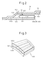
- Fig. 2 is a drawing similar to Fig. 8 which explains the cooling system of the combustion tube 5b of the present embodiment.
- combustion tube 5b is formed by joining plural cylindrical shells 55 having different diameters in the axial direction.
- the cylindrical shells 55 are joined to each other through stepped diameter portions and act as structural members forming a combustion tube 5a.
- a cylindrical heat insulating member 550 is disposed in each cylindrical shell and acts as a wall of a combustion chamber.
- Fig. 3 shows a construction of the heat insulating member 550 in this embodiment.
- the heat insulating member 550 is a cylindrical member having a relatively large wall thickness and numerous cooling air passage 551, each having a rectangular shaped cross section, are extending in the axial direction within the wall thereof.
- the heat insulating member 550 in this embodiment is formed, for example, by joining two cylindrical members (an outer cylindrical member 550a and an inner cylindrical member 550b) using such as brazing. Numerous grooves having rectangular shaped cross sections and extending in the axial direction are formed on the outer periphery of the inner cylindrical member 550b.
- the outer cylindrical member 550a is provided with a flat inner surface.
- the heat insulating member 550 is formed by joining the outer surface of the inner cylindrical member 550b and the inner surface of the outer cylindrical member 550a by, for example, brazing after inserting the inner cylindrical member 550b into the bore of the outer cylindrical member 550a.
- the axial grooves on the outer periphery of the inner cylindrical member 550b are covered by the inner surface of the outer cylindrical member 550a and the numerous cooling air passages 551 having rectangular shaped cross sections and independent from each other are formed in the wall of the heat insulating member 550.
- the heat insulating member 550 is joined to the inner surface of the shell 55 at the end of smaller diameter portion 550d of the shell. Further, a seal ring 553 made of a heat resistant material is interposed between the outer surface of the heat insulating member 550 and inner surface of the shell 55. The seal ring 553 seals the space between the outer surface of the heat insulating member 550 and the inner surface of the shell 55 and prevents the cooling air from flowing through this space.
- a portion of the pressurized air in the casing 7 flows into a cooling air chamber 559 in the shell 55 disposed at the end of the heat insulating member 550 through cooling air inlet openings 557 disposed around the smaller end portion of the shell 55. Cooling air further flows into the respective cooling air passages 55a from the cooling air chamber 559. After passing through the respective cooling air passages 550a and cooling the heat insulating member 550 by convective cooling, cooling air is injected from the cooling air passages 550a along the inner surface of the adjacent heat insulating member 550. Thus, a film of air for cooling the inner surface of the adjacent heat insulating member 550 (i.e., the inner surface of the combustion chamber) is formed.
- the seal ring 553 is disposed around the outer surface of the heat insulating member 550, the flow of the cooling air through the clearance between the outer surface of the heat insulating member 550 and the inner surface of the shell 55 is blocked even though the clearance is large in this embodiment. Therefore, the tolerance for machining and assembly of the heat insulating member 550 and shell 55 is not necessarily small except for the portion at which the heat insulating member 550 is joined to the shell 55. Thus, cost and time required for manufacturing the combustor can be reduced.
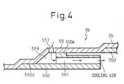
- the space between the heat insulating member 550 and the shell 55 is sealed by the seal ring 553 in this embodiment, the space can be sealed by attaching the outer circumference of the heat insulating member 550 to the inner surface of the shell 50 at the portion between the inlet and the outlet of the cooling air passage 550a (550e in Fig. 4) by, for example, brazing as shown in Fig. 4.
- the heat insulating member 550 is attached to the shell 55 at the seal portion 550e, as well as at the end portion 550d, the strength of the combustion tube assembly further increases.
- Fig. 5 is a longitudinal section view similar to Fig. 1 which shows a gas turbine combustor according to the second embodiment of the present invention.
- cooling of the combustor is performed using cooling steam.
- the construction of the combustor is different from that of Fig. 1 in that the combustor portion 5 of the combustor 1 is a one-piece construction in which the combustion tube 5b and the tail pipe 5b are formed as an integral part. Therefore, the combustor portion 5 will be referred to as a combustion tube 5 in this embodiment.
- the wall of the combustion tube 5 is cooled by cooling steam along whole length of the combustion tube 5.
- cooling steam is supplied at the middle portion of the combustor in Fig. 1 (i.e., the portion where the combustion tube 5b and the tail pipe 5a in Fig. 1 is joined) and divided into two flows of cooling steam (i.e., a flow towards upstream and flow towards downstream), a pair of cooling steam inlet pipes 511, 513 and a pair of cooling steam outlet pipes 515, 517 are connected to the combustion tube 5 in this embodiment.
- the cooling steam inlet pipe 511 and outlet pipe 515 are connected to the wall of the combustion tube 5 at the outlet end (the turbine end) thereof, and the cooling steam inlet pipe 513 and the outlet pipe 517 are connected to the wall of the combustion tube 5 at the inlet end (the main fuel nozzle side end) thereof.
- first cooling steam passage 523 which is connected to the inlet pipe 511 and outlet pipe 517 and second cooling passages 521 connected to the inlet pipe 513 and outlet pipe 515 are formed within the wall of the combustion tube 5. Cooling steam flows through the first cooling steam passages 523 in the upstream direction (i.e., from the outlet side to the inlet side of the combustion tube 5) and in the downstream direction (i.e., from the inlet side to the outlet side of the combustion tube 5).
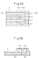
- Figs. 6A and 6B schematically show the arrangement of the first cooling steam passages 523 and the second cooling steam passages 521 in the wall of the combustion tube 5.
- Fig. 6A shows the arrangement of the passages along the circumference of the combustion tube 5 at the outlet portion 52 thereof.
- the first cooling steam passages 523 and the second cooling steam passages 521 are disposed alternately around the circumference of combustion tube 5.
- Fig. 6B is a section view taken along the line "B"-"B" in Fig. 6A. As shown in Fig.
- annular steam inlet manifold 513a which connects the second cooling steam passages 521 to the steam inlet pipe 513 and an annular steam outlet manifold 517a which connects the first cooling steam passages 523 to the steam outlet pipe 517 are formed around the outlet portion 52 of the combustion tube 5.
- annular steam inlet manifold 511a and an annular steam outlet manifold 515a are formed around the inlet portion of the combustion tube 5.
- the arrangement of the steam manifolds at the inlet of the combustion tube 5 is similar to the steam manifolds in Figs. 6A and 6B.
- the annular inlet manifold 511a connects the first cooling steam passages 523 to the steam inlet pipe 511 and an annular steam outlet manifold 515a connects the first cooling steam passages 523 to the steam outlet pipe 515.
- flow rates of cooling steam in the first and second cooling steam passages 523, 521 are adjusted in such a manner that the inlet steam temperatures in the inlet manifolds 511a and 513a are the same, and the outlet steam temperatures in the outlet manifolds 515a and 517a are the same.
- the steam temperature in the inlet manifolds 511a and 513a i.e., the steam temperature at the inlet of the cooling steam passages 521 and 523
- the steam temperature in the outlet manifolds 515a and 517a i.e., the steam temperature at the outlet of the cooling steam passages 521 and 523) is adjusted to about 600°C.
- the average temperatures of the steam flowing through the cooling steam passages 521 and 523 becomes nearly uniform along the length of the cooling steam passages 521 and 523.
- the temperature of the combustion gas is not uniform along the axis of the combustion tube 5. Namely, the temperature of the combustion gas is relatively high at the inlet side of the combustion tube 5 and relatively low at the outlet side of the combustion tube 5.
- the wall temperature of the combustion tube 5 (the metal temperature) changes in accordance with the steam temperature in the cooling steam passages. More specifically, difference between the metal temperature of the combustion tube 5 and the steam temperature in the cooling steam passages is nearly constant regardless of the combustion gas temperature in the combustion tube 5.
- the cooling steam in the cooling steam passages 521 and 523 flows in the direction opposite to each other, the average steam temperature in the cooling steam passages 521 and 523 becomes nearly constant along the length of the combustion tube 5. Therefore, the metal temperature of the combustion tube 5 also becomes nearly constant along the length of the combustion tube 5 and, since the excessive cooling of the wall of the combustion tube does not occur, the consumption of the cooling steam can be reduced in the present embodiment.
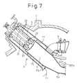
- Fig. 7 is a longitudinal section view of a gas turbine combustor according to the third embodiment of the present invention. In this embodiment, both steam and air are used for cooling the combustor.
- the combustor portion 5 of the combustor 1 is formed as a one-piece member and is referred to as combustion tube 5.
- numeral 507 denotes a cooling steam inlet pipe connected to the portion of the combustion tube 5 at the middle of the length thereof
- 509b denotes a cooling steam outlet pipe connected to the portion of the combustion tube 5 at the outlet thereof.
- the downstream half of the combustion tube 5 is cooled by cooling steam. Namely, cooling steam is introduced from the inlet pipe 507 into cooling steam passages formed in the wall of the downstream half of the combustion tube 5 and, after cooling the downstream half of the combustion tube 5, collected through the outlet pipe 509b.
- the upstream half of the combustor is cooled by air. Further, combustion air supplied to the nozzle portion 3 is used for cooling the upstream half of the combustion tube.
- a cylindrical cooling shroud 71 is disposed around the upstream half of the combustion tube 5.
- the shroud 71 extends from the end of the nozzle portion to the middle of the length of the combustion tube 5.
- One end (a upstream end) of the shroud 71 is attached to the nozzle portion 3 of the combustor at the portion upstream of the combustion air inlet 35 and forms a closed end.
- the other end (a downstream end) of the shroud 71 is provided with funnel shaped inlet cone 73 and communicates with the inside of the casing 7.
- the annular space between the shroud 71 and the combustion tube 5 acts as a cooling air passage 75 for cooling the combustion tube 5.
- combustion air in the casing 7 flows into the cooling air passage 75 through the inlet cone 73 and flows into the nozzle portion 3 of the combustor 1 from the combustion air inlet openings 35 after passing through the cooling air passage 75.
- Combustion air flowing into the nozzle portion 3 flows into the combustion tube 5 through the pilot nozzle 31 and main nozzle 33.
- the wall of the upstream half of the combustion tube 5 is cooled by combustion air by convective cooling.
- the temperature of combustion air is relatively low in the upstream half of the combustion tube 5 and the heat load of the upstream half of the combustion tube is smaller than that of the downstream half of the combustion tube 5. Since the heat load is relatively low, the wall of the upstream half of the combustion tube can be sufficiently cooled by convective cooling using cooling air without using film air cooling.
- downstream half of the combustion tube 5, where the heat load of the wall is relatively high is cooled by conventional steam cooling system and the upstream half of the combustion tube 5, where the heat load of the wall is relatively low, is cooled solely by convective cooling using combustion air.
- combustion air passes through the cooling air passage 75 before flowing into the combustor 1.
- the cooling air passage 75 is formed by a relatively large annular clearance between the shroud 71 and combustion tube 5, the flow path thereof is relatively short. Therefore, pressure drop of the combustion air through the cooling air passage 71 is relatively small.
- the pressure of air after cooling the combustion tube 5 is still sufficiently high for use as combustion air.
- all the air passing through the cooling air passage 75 is introduced into the nozzle portion 3 and used for combustion air in this embodiment. Since all of cooling air is used as combustion air and no cooling air is discharged into the combustion tube 5 directly in this embodiment, dilution of combustion gas by cooling air does not occur.
- cooling air after cooling the combustion tube 5 is used as combustion air in this embodiment, consumption of cooling air required for cooling the combustor is practically negligible. Therefore, a temperature drop of combustion gas, as well as a decrease in the amount of combustion air, can be prevented, at the same time, in this embodiment.
Landscapes
- Engineering & Computer Science (AREA)
- Chemical & Material Sciences (AREA)
- Combustion & Propulsion (AREA)
- Mechanical Engineering (AREA)
- General Engineering & Computer Science (AREA)
- Turbine Rotor Nozzle Sealing (AREA)
Applications Claiming Priority (2)
| Application Number | Priority Date | Filing Date | Title |
|---|---|---|---|
| JP2000106883A JP2001289062A (ja) | 2000-04-07 | 2000-04-07 | ガスタービン燃焼器の壁面冷却構造 |
| JP2000106883 | 2000-04-07 |
Publications (3)
| Publication Number | Publication Date |
|---|---|
| EP1143201A2 true EP1143201A2 (de) | 2001-10-10 |
| EP1143201A3 EP1143201A3 (de) | 2001-12-19 |
| EP1143201B1 EP1143201B1 (de) | 2005-06-29 |
Family
ID=18619982
Family Applications (1)
| Application Number | Title | Priority Date | Filing Date |
|---|---|---|---|
| EP01108391A Expired - Lifetime EP1143201B1 (de) | 2000-04-07 | 2001-04-03 | Kühlungssystem einer Gasturbinenbrennkammer |
Country Status (5)
| Country | Link |
|---|---|
| US (1) | US6463742B2 (de) |
| EP (1) | EP1143201B1 (de) |
| JP (1) | JP2001289062A (de) |
| CA (1) | CA2342685C (de) |
| DE (1) | DE60111670T2 (de) |
Cited By (7)
| Publication number | Priority date | Publication date | Assignee | Title |
|---|---|---|---|---|
| EP1306619A3 (de) * | 2001-10-29 | 2004-03-10 | Mitsubishi Heavy Industries, Ltd. | Gasturbine und Brennkammer |
| US7870738B2 (en) | 2006-09-29 | 2011-01-18 | Siemens Energy, Inc. | Gas turbine: seal between adjacent can annular combustors |
| CN103185354A (zh) * | 2012-01-03 | 2013-07-03 | 通用电气公司 | 用于冷却过渡喷嘴的方法和系统 |
| EP2187021A4 (de) * | 2007-09-25 | 2015-03-11 | Mitsubishi Heavy Ind Ltd | Gasturbinenbrennkammer |
| CN114294112A (zh) * | 2021-10-20 | 2022-04-08 | 中国航发四川燃气涡轮研究院 | 带转接密封结构的双通道管路装置 |
| CN116733613A (zh) * | 2023-08-10 | 2023-09-12 | 成都中科翼能科技有限公司 | 一种燃气轮机的过渡段结构 |
| EP4596971A4 (de) * | 2022-11-07 | 2025-12-31 | Mitsubishi Heavy Ind Aero Engines Ltd | Zylindrischer körper |
Families Citing this family (33)
| Publication number | Priority date | Publication date | Assignee | Title |
|---|---|---|---|---|
| US6890148B2 (en) * | 2003-08-28 | 2005-05-10 | Siemens Westinghouse Power Corporation | Transition duct cooling system |
| US7178341B2 (en) * | 2004-06-17 | 2007-02-20 | Siemens Power Generation, Inc. | Multi-zone tubing assembly for a transition piece of a gas turbine |
| US8015818B2 (en) * | 2005-02-22 | 2011-09-13 | Siemens Energy, Inc. | Cooled transition duct for a gas turbine engine |
| US7559203B2 (en) * | 2005-09-16 | 2009-07-14 | Pratt & Whitney Canada Corp. | Cooled support boss for a combustor in a gas turbine engine |
| US7827801B2 (en) * | 2006-02-09 | 2010-11-09 | Siemens Energy, Inc. | Gas turbine engine transitions comprising closed cooled transition cooling channels |
| JP4969384B2 (ja) * | 2007-09-25 | 2012-07-04 | 三菱重工業株式会社 | ガスタービン燃焼器の冷却構造 |
| JP5260402B2 (ja) * | 2009-04-30 | 2013-08-14 | 三菱重工業株式会社 | 板状体の製造方法、板状体、ガスタービン燃焼器およびガスタービン |
| US9316155B2 (en) * | 2013-03-18 | 2016-04-19 | General Electric Company | System for providing fuel to a combustor |
| US9494081B2 (en) | 2013-05-09 | 2016-11-15 | Siemens Aktiengesellschaft | Turbine engine shutdown temperature control system with an elongated ejector |
| US10520193B2 (en) | 2015-10-28 | 2019-12-31 | General Electric Company | Cooling patch for hot gas path components |
| US10830442B2 (en) | 2016-03-25 | 2020-11-10 | General Electric Company | Segmented annular combustion system with dual fuel capability |
| US10641491B2 (en) | 2016-03-25 | 2020-05-05 | General Electric Company | Cooling of integrated combustor nozzle of segmented annular combustion system |
| US11428413B2 (en) | 2016-03-25 | 2022-08-30 | General Electric Company | Fuel injection module for segmented annular combustion system |
| US10584876B2 (en) | 2016-03-25 | 2020-03-10 | General Electric Company | Micro-channel cooling of integrated combustor nozzle of a segmented annular combustion system |
| US10584880B2 (en) | 2016-03-25 | 2020-03-10 | General Electric Company | Mounting of integrated combustor nozzles in a segmented annular combustion system |
| US10641176B2 (en) | 2016-03-25 | 2020-05-05 | General Electric Company | Combustion system with panel fuel injector |
| US10520194B2 (en) | 2016-03-25 | 2019-12-31 | General Electric Company | Radially stacked fuel injection module for a segmented annular combustion system |
| US10605459B2 (en) | 2016-03-25 | 2020-03-31 | General Electric Company | Integrated combustor nozzle for a segmented annular combustion system |
| US10563869B2 (en) | 2016-03-25 | 2020-02-18 | General Electric Company | Operation and turndown of a segmented annular combustion system |
| US11156362B2 (en) | 2016-11-28 | 2021-10-26 | General Electric Company | Combustor with axially staged fuel injection |
| US10690350B2 (en) | 2016-11-28 | 2020-06-23 | General Electric Company | Combustor with axially staged fuel injection |
| JP6966354B2 (ja) * | 2018-02-28 | 2021-11-17 | 三菱パワー株式会社 | ガスタービン燃焼器 |
| CN109404966B (zh) * | 2018-12-04 | 2024-03-22 | 新奥能源动力科技(上海)有限公司 | 燃烧室头部装置及燃气轮机 |
| JP7112342B2 (ja) * | 2019-01-25 | 2022-08-03 | 三菱重工業株式会社 | ガスタービン燃焼器及びガスタービン |
| US11994293B2 (en) | 2020-08-31 | 2024-05-28 | General Electric Company | Impingement cooling apparatus support structure and method of manufacture |
| US11614233B2 (en) | 2020-08-31 | 2023-03-28 | General Electric Company | Impingement panel support structure and method of manufacture |
| US11460191B2 (en) | 2020-08-31 | 2022-10-04 | General Electric Company | Cooling insert for a turbomachine |
| US11371702B2 (en) | 2020-08-31 | 2022-06-28 | General Electric Company | Impingement panel for a turbomachine |
| US11994292B2 (en) | 2020-08-31 | 2024-05-28 | General Electric Company | Impingement cooling apparatus for turbomachine |
| US11255545B1 (en) | 2020-10-26 | 2022-02-22 | General Electric Company | Integrated combustion nozzle having a unified head end |
| KR102661014B1 (ko) * | 2022-03-30 | 2024-04-25 | 한국기계연구원 | 덕트 조립체 및 이를 포함하는 연소기 |
| US11767766B1 (en) | 2022-07-29 | 2023-09-26 | General Electric Company | Turbomachine airfoil having impingement cooling passages |
| CN121408082B (zh) * | 2025-12-29 | 2026-03-20 | 中国人民解放军国防科技大学 | 空天发动机高温表面的再生冷却隔热结构及空天发动机 |
Family Cites Families (10)
| Publication number | Priority date | Publication date | Assignee | Title |
|---|---|---|---|---|
| US4474014A (en) * | 1981-09-17 | 1984-10-02 | United Technologies Corporation | Partially unshrouded swirler for combustion chambers |
| JPH0648095B2 (ja) * | 1985-04-18 | 1994-06-22 | 石川島播磨重工業株式会社 | ガスタ−ビン燃焼器等のライナ−冷却構造 |
| JPH03267618A (ja) | 1990-03-19 | 1991-11-28 | Hitachi Ltd | ガスタービン燃焼器の冷却構造 |
| DE4137638C2 (de) * | 1991-11-15 | 1994-08-11 | Mtu Muenchen Gmbh | Bauteil mit einer vor thermischer Belastung zu schützenden Wand |
| US5223179A (en) | 1992-03-26 | 1993-06-29 | The Procter & Gamble Company | Cleaning compositions with glycerol amides |
| US5363654A (en) * | 1993-05-10 | 1994-11-15 | General Electric Company | Recuperative impingement cooling of jet engine components |
| US5950417A (en) * | 1996-07-19 | 1999-09-14 | Foster Wheeler Energy International Inc. | Topping combustor for low oxygen vitiated air streams |
| JP3825090B2 (ja) * | 1996-07-24 | 2006-09-20 | 三菱重工業株式会社 | コンバインドサイクル発電プラント |
| US6018950A (en) * | 1997-06-13 | 2000-02-01 | Siemens Westinghouse Power Corporation | Combustion turbine modular cooling panel |
| JP3567065B2 (ja) * | 1997-07-31 | 2004-09-15 | 株式会社東芝 | ガスタービン |
-
2000
- 2000-04-07 JP JP2000106883A patent/JP2001289062A/ja not_active Withdrawn
-
2001
- 2001-04-02 CA CA002342685A patent/CA2342685C/en not_active Expired - Fee Related
- 2001-04-03 DE DE60111670T patent/DE60111670T2/de not_active Expired - Fee Related
- 2001-04-03 EP EP01108391A patent/EP1143201B1/de not_active Expired - Lifetime
- 2001-04-05 US US09/825,881 patent/US6463742B2/en not_active Expired - Fee Related
Cited By (11)
| Publication number | Priority date | Publication date | Assignee | Title |
|---|---|---|---|---|
| EP1306619A3 (de) * | 2001-10-29 | 2004-03-10 | Mitsubishi Heavy Industries, Ltd. | Gasturbine und Brennkammer |
| US7870738B2 (en) | 2006-09-29 | 2011-01-18 | Siemens Energy, Inc. | Gas turbine: seal between adjacent can annular combustors |
| EP2187021A4 (de) * | 2007-09-25 | 2015-03-11 | Mitsubishi Heavy Ind Ltd | Gasturbinenbrennkammer |
| CN103185354A (zh) * | 2012-01-03 | 2013-07-03 | 通用电气公司 | 用于冷却过渡喷嘴的方法和系统 |
| US9243506B2 (en) | 2012-01-03 | 2016-01-26 | General Electric Company | Methods and systems for cooling a transition nozzle |
| CN103185354B (zh) * | 2012-01-03 | 2016-12-28 | 通用电气公司 | 用于冷却过渡喷嘴的方法和系统 |
| CN114294112A (zh) * | 2021-10-20 | 2022-04-08 | 中国航发四川燃气涡轮研究院 | 带转接密封结构的双通道管路装置 |
| CN114294112B (zh) * | 2021-10-20 | 2023-06-13 | 中国航发四川燃气涡轮研究院 | 带转接密封结构的双通道管路装置 |
| EP4596971A4 (de) * | 2022-11-07 | 2025-12-31 | Mitsubishi Heavy Ind Aero Engines Ltd | Zylindrischer körper |
| CN116733613A (zh) * | 2023-08-10 | 2023-09-12 | 成都中科翼能科技有限公司 | 一种燃气轮机的过渡段结构 |
| CN116733613B (zh) * | 2023-08-10 | 2023-10-20 | 成都中科翼能科技有限公司 | 一种燃气轮机的过渡段结构 |
Also Published As
| Publication number | Publication date |
|---|---|
| JP2001289062A (ja) | 2001-10-19 |
| EP1143201A3 (de) | 2001-12-19 |
| DE60111670T2 (de) | 2006-05-04 |
| DE60111670D1 (de) | 2005-08-04 |
| CA2342685C (en) | 2004-12-14 |
| US6463742B2 (en) | 2002-10-15 |
| EP1143201B1 (de) | 2005-06-29 |
| US20010027653A1 (en) | 2001-10-11 |
| CA2342685A1 (en) | 2001-10-07 |
Similar Documents
| Publication | Publication Date | Title |
|---|---|---|
| US6463742B2 (en) | Gas turbine steam-cooled combustor with alternately counter-flowing steam passages | |
| US6698207B1 (en) | Flame-holding, single-mode nozzle assembly with tip cooling | |
| CN100529548C (zh) | 燃气涡轮燃烧室的多文丘利管燃料喷射器 | |
| EP2329121B1 (de) | Mehrkanalige brennstoffsammelleitung und konstruktionsverfahren | |
| US11428413B2 (en) | Fuel injection module for segmented annular combustion system | |
| US6786046B2 (en) | Dual-mode nozzle assembly with passive tip cooling | |
| US20170276362A1 (en) | Turbine Nozzle Cooling with Panel Fuel Injector | |
| US8973369B2 (en) | Gas-turbine burner having inflow guide means | |
| EP1010946A2 (de) | Kraftstoffeinspritzung für eine Gasturbinenbrennkammer | |
| US20170276358A1 (en) | Micro-Channel Cooling of Integrated Combustor Nozzle of a Segmented Annular Combustion System | |
| JP5399015B2 (ja) | ガスタービンエンジン用の燃料ノズル及びそれを製作する方法 | |
| EP3211318B1 (de) | Nur-gas-kartusche für eine vormischbrennstoffdüse | |
| EP3889508B1 (de) | Gasturbinenbrennkammer | |
| US20160033134A1 (en) | Seal in combustor nozzle of gas turbine engine | |
| JP2023050983A (ja) | トランジションピース、燃焼器及びガスタービンエンジン | |
| US9157370B2 (en) | Burner assembly | |
| EP1381812B1 (de) | Vormischende turbinenverbrennungskammer | |
| US9057524B2 (en) | Shielding wall for a fuel supply duct in a turbine engine | |
| JP7326399B2 (ja) | トランジションピース、燃焼器及びガスタービンエンジン | |
| US7926279B2 (en) | Extended life fuel nozzle | |
| EP4067746B1 (de) | Brennkammer mit nachlauferreger | |
| CN113819488B (zh) | 具有燃烧室空气旁路的燃气轮机的组件 | |
| US11242990B2 (en) | Liner cooling structure with reduced pressure losses and gas turbine combustor having same |
Legal Events
| Date | Code | Title | Description |
|---|---|---|---|
| PUAI | Public reference made under article 153(3) epc to a published international application that has entered the european phase |
Free format text: ORIGINAL CODE: 0009012 |
|
| 17P | Request for examination filed |
Effective date: 20010403 |
|
| AK | Designated contracting states |
Kind code of ref document: A2 Designated state(s): AT BE CH CY DE DK ES FI FR GB GR IE IT LI LU MC NL PT SE TR Kind code of ref document: A2 Designated state(s): CH DE FR GB IT LI |
|
| AX | Request for extension of the european patent |
Free format text: AL;LT;LV;MK;RO;SI |
|
| PUAL | Search report despatched |
Free format text: ORIGINAL CODE: 0009013 |
|
| AK | Designated contracting states |
Kind code of ref document: A3 Designated state(s): AT BE CH CY DE DK ES FI FR GB GR IE IT LI LU MC NL PT SE TR |
|
| AX | Request for extension of the european patent |
Free format text: AL;LT;LV;MK;RO;SI |
|
| RIC1 | Information provided on ipc code assigned before grant |
Free format text: 7F 23R 3/06 A, 7F 23R 3/10 B, 7F 23L 7/00 B |
|
| AKX | Designation fees paid |
Free format text: CH DE FR GB IT LI |
|
| 17Q | First examination report despatched |
Effective date: 20040920 |
|
| GRAP | Despatch of communication of intention to grant a patent |
Free format text: ORIGINAL CODE: EPIDOSNIGR1 |
|
| GRAS | Grant fee paid |
Free format text: ORIGINAL CODE: EPIDOSNIGR3 |
|
| GRAA | (expected) grant |
Free format text: ORIGINAL CODE: 0009210 |
|
| AK | Designated contracting states |
Kind code of ref document: B1 Designated state(s): CH DE FR GB IT LI |
|
| PG25 | Lapsed in a contracting state [announced via postgrant information from national office to epo] |
Ref country code: IT Free format text: LAPSE BECAUSE OF FAILURE TO SUBMIT A TRANSLATION OF THE DESCRIPTION OR TO PAY THE FEE WITHIN THE PRESCRIBED TIME-LIMIT;WARNING: LAPSES OF ITALIAN PATENTS WITH EFFECTIVE DATE BEFORE 2007 MAY HAVE OCCURRED AT ANY TIME BEFORE 2007. THE CORRECT EFFECTIVE DATE MAY BE DIFFERENT FROM THE ONE RECORDED. Effective date: 20050629 Ref country code: LI Free format text: LAPSE BECAUSE OF FAILURE TO SUBMIT A TRANSLATION OF THE DESCRIPTION OR TO PAY THE FEE WITHIN THE PRESCRIBED TIME-LIMIT Effective date: 20050629 Ref country code: CH Free format text: LAPSE BECAUSE OF FAILURE TO SUBMIT A TRANSLATION OF THE DESCRIPTION OR TO PAY THE FEE WITHIN THE PRESCRIBED TIME-LIMIT Effective date: 20050629 |
|
| REG | Reference to a national code |
Ref country code: GB Ref legal event code: FG4D |
|
| REG | Reference to a national code |
Ref country code: CH Ref legal event code: EP |
|
| REF | Corresponds to: |
Ref document number: 60111670 Country of ref document: DE Date of ref document: 20050804 Kind code of ref document: P |
|
| REG | Reference to a national code |
Ref country code: CH Ref legal event code: PL |
|
| PG25 | Lapsed in a contracting state [announced via postgrant information from national office to epo] |
Ref country code: GB Free format text: LAPSE BECAUSE OF NON-PAYMENT OF DUE FEES Effective date: 20060403 |
|
| PLBE | No opposition filed within time limit |
Free format text: ORIGINAL CODE: 0009261 |
|
| STAA | Information on the status of an ep patent application or granted ep patent |
Free format text: STATUS: NO OPPOSITION FILED WITHIN TIME LIMIT |
|
| 26N | No opposition filed |
Effective date: 20060330 |
|
| EN | Fr: translation not filed | ||
| PG25 | Lapsed in a contracting state [announced via postgrant information from national office to epo] |
Ref country code: FR Free format text: LAPSE BECAUSE OF FAILURE TO SUBMIT A TRANSLATION OF THE DESCRIPTION OR TO PAY THE FEE WITHIN THE PRESCRIBED TIME-LIMIT Effective date: 20060825 |
|
| GBPC | Gb: european patent ceased through non-payment of renewal fee |
Effective date: 20060403 |
|
| PGFP | Annual fee paid to national office [announced via postgrant information from national office to epo] |
Ref country code: DE Payment date: 20070329 Year of fee payment: 7 |
|
| PG25 | Lapsed in a contracting state [announced via postgrant information from national office to epo] |
Ref country code: FR Free format text: LAPSE BECAUSE OF FAILURE TO SUBMIT A TRANSLATION OF THE DESCRIPTION OR TO PAY THE FEE WITHIN THE PRESCRIBED TIME-LIMIT Effective date: 20050629 |
|
| PG25 | Lapsed in a contracting state [announced via postgrant information from national office to epo] |
Ref country code: DE Free format text: LAPSE BECAUSE OF NON-PAYMENT OF DUE FEES Effective date: 20081101 |