EP1143230A2 - Capteur de mesure de contraintes et de forces - Google Patents
Capteur de mesure de contraintes et de forces Download PDFInfo
- Publication number
- EP1143230A2 EP1143230A2 EP01810330A EP01810330A EP1143230A2 EP 1143230 A2 EP1143230 A2 EP 1143230A2 EP 01810330 A EP01810330 A EP 01810330A EP 01810330 A EP01810330 A EP 01810330A EP 1143230 A2 EP1143230 A2 EP 1143230A2
- Authority
- EP
- European Patent Office
- Prior art keywords
- legs
- measuring elements
- strain
- measuring
- measurement sensor
- Prior art date
- Legal status (The legal status is an assumption and is not a legal conclusion. Google has not performed a legal analysis and makes no representation as to the accuracy of the status listed.)
- Granted
Links
Images
Classifications
-
- G—PHYSICS
- G01—MEASURING; TESTING
- G01L—MEASURING FORCE, STRESS, TORQUE, WORK, MECHANICAL POWER, MECHANICAL EFFICIENCY, OR FLUID PRESSURE
- G01L5/00—Apparatus for, or methods of, measuring force, work, mechanical power, or torque, specially adapted for specific purposes
- G01L5/0004—Force transducers adapted for mounting in a bore of the force receiving structure
Definitions
- the invention relates to a sensor for electrical Measure positive and negative strains and forces in assembly holes of structures at any depth, which transducer is strain or force-sensitive electrical signals generating, with at least one elastic Part underlaid measuring elements, means for frictionally pressing the Elements on the wall of the mounting hole, an extension tube for Leading the means mentioned and signal cables leading to an electronic evaluation system lead, includes.
- Measurement sensors which are cylindrical or band-shaped elastic bodies generate a contact pressure that is sufficient, sensitive to strain Measuring elements non-positively to a bore wall press.
- Such sensors have the disadvantage that they are only one small bore tolerance can compensate because the elastic part as soon as it is pressed too much over the guide housing to flow away begins. This undesirable process is caused by elevated temperatures such as they occur in the industrial environment, accelerates. They also have them Measuring sensor an insufficient mechanical limitation of the tightening path, so that if the assembly is not carried out correctly, the protective sleeve the raw contact pressure can be blown up.
- the inventor has set himself the task of a sensor of the beginning mentioned type to create the strains or forces in a hole can easily measure at any depth, and thus the aforementioned Disadvantages are eliminated.
- the object is achieved in that the means for pressing of the measuring elements two legs pivotable at the base with one outside milling 15 for the elastic parts and an inside Suit for a wedge with measuring elements, which wedge by means of a a spindle guided spindle in the longitudinal direction of the extension tube is displaceable and causes a spreading movement of the legs.
- strain gauges with a herringbone or cross pattern are used, a temperature-compensated full bridge can be easily created form.
- the sensors according to the invention preferably have a Protective sleeve in which two resilient legs with the expansion-sensitive Measuring elements and a wedge for generating the contact pressure are accommodated.
- the elastic part Since the elastic part is inserted in a cut in the leg, it can never protrude beyond the guide housing as specified by the production, with the permanent disadvantage of flowing away in any installation situation is avoided.
- strain-sensitive elements are protected against environmental influences and can therefore be used or installed and removed several times.
- the pressure on the legs is so strong that the entire sensor is held in the bore and thus the fastener and strain-sensitive measuring element form a unit.
- the wedge is appropriately dimensioned with regard to the mechanical mass, that it reaches when the maximum permitted expansion of the legs mechanical stop.
- Form in the reverse axial direction advantageous lugs on the two legs a stop that prevents that the wedge is turned back too far and the protective sleeve is destroyed.
- the sensor measures correct even if the preload due to unfavorable influences the spindle would wear off completely.
- the sensor can even in holes with very rough tolerances because these Tolerances cannot be compensated for by the elastic part.
- the protective sleeve can be connected to the base of the legs, e.g. B. glued or welded, with which measurements can also be carried out without interference in an industrial environment can be.
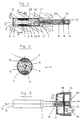
- a sensor 14 shown in FIGS. 1 and 2 is installed in a Mounting hole 13. This can be a through hole or a blind hole.
- the Sensor 14 contains the resiliently held legs 3, on the Outside in a cutout 15 with a protruding elastic part 2 strain-sensitive measuring elements 1 lying thereon are attached.
- the legs 3 have on their inside a light suit 23, the corresponds to that of an associated wedge 5.
- the wedge 5 is with a provided centrally attached thread in which a spindle 8 is screwed is.
- the wedge 5 is made of a material that has a low inclination for cold welding with the material of the legs 3. As special Bronze has proven to be favorable.
- the angle of the wedge 5 is dimensioned that it is self-locking. Angles in the area have proven to be particularly favorable proven from 2 to 6 ° with respect to the longitudinal axis L of the spindle 8.
- the wedge 5 is moved in the axial direction L by means of the spindle 8. Thereby perform the legs 3 a slight spreading movement when tightening outside, so that the strain or force-sensitive measuring elements 1 to one Protective sleeve 9 are pressed.
- This protective sleeve 9 becomes slightly oval deformed and the strain or force-sensitive measuring elements 1 finally pressed non-positively against the wall of the mounting hole 13.
- the Pressure on the strain or force sensitive measuring elements 1 must be so be high that between the measuring element 1, the protective sleeve 9 and the bore wall a positive connection is created. So on the one hand forces acting on structure 24 by means of strain-sensitive forces Elements 1 are measured, or on the other hand across Forces occurring for drilling with correspondingly arranged force-sensitive Measuring elements 1 are measured.
- the sensor 14 in the tensioned state without additional Bracing mechanisms held firmly in the mounting hole 13.
- the measuring and the tensioning element form a unit.
- the spindle 8 is clamped by means of a clamping nut 12.
- a preferred one Embodiment of the clamping nut 12 has an externally accessible Hexagon on.
- a nose 4 limits the axial range of displacement the wedge 5.
- Signal cables 10 are through grooves 16 in the legs 3 and through holes 17 in the base of the legs 3 of the spindle 8 along to an electronic evaluation system 18 (Fig. 3) performed.
- Fig. 2 is the jacket of the protective sleeve 9, which is preferably made of the same Material such as the base 7 of the legs 3 is clearly visible.
- the protective sleeve 9 deforms slightly oval when subjected to force.
- the wedge 5 is on the side not round, but flat, which is a relatively large oval Allows deformation of the protective sleeve 9.
- the senor 14 can also be mounted in mounting holes 13 are manufactured with rough tolerances, which are of great benefit elevated.
- FIG. 3 shows the sensor 14 with an elongated spindle 8 and a Extension tube 11.
- the electrical cables 10 are along the spindle 8, which can not turn, led to the evaluation electronics 18. This in turn is connected to a plug 19.
- the clamping nut 12 is on the one hand freely supported in the extension tube 11 and is on the other hand held by a cover 20 in the extension tube 11.
- the elongated spindle 8 is mounted on the sensor side the other side is a slot or, as shown, a hexagon socket provided for torque introduction.
- the special design of a housing 21 allows the spindle 8 to be must inevitably move axially in both directions L if the at the Turning nut 12 is rotated accordingly. This makes the wedge 5 secure pushed back, even if there is a tendency to get stuck would. This means that the sensor can also be removed 14 guaranteed.
- the housing 21 for the evaluation electronics 18 is made very small, omits this and leads the cables 10 laterally through a radial bore 22, one obtains a sensor 14 as a variant, which is very compact but still has all the advantages described above.
Landscapes
- Physics & Mathematics (AREA)
- General Physics & Mathematics (AREA)
- Force Measurement Appropriate To Specific Purposes (AREA)
- Measurement Of Length, Angles, Or The Like Using Electric Or Magnetic Means (AREA)
Applications Claiming Priority (2)
| Application Number | Priority Date | Filing Date | Title |
|---|---|---|---|
| CH697002000 | 2000-04-07 | ||
| CH6972000A CH694926A5 (de) | 2000-04-07 | 2000-04-07 | Messwertaufnehmer zum Messen von Dehnungen auf ebenen oder gewoelbten Oberflaechen. |
Publications (3)
| Publication Number | Publication Date |
|---|---|
| EP1143230A2 true EP1143230A2 (fr) | 2001-10-10 |
| EP1143230A3 EP1143230A3 (fr) | 2002-09-04 |
| EP1143230B1 EP1143230B1 (fr) | 2009-08-19 |
Family
ID=4529717
Family Applications (1)
| Application Number | Title | Priority Date | Filing Date |
|---|---|---|---|
| EP20010810330 Expired - Lifetime EP1143230B1 (fr) | 2000-04-07 | 2001-04-02 | Capteur de mesure de contraintes et de forces |
Country Status (2)
| Country | Link |
|---|---|
| EP (1) | EP1143230B1 (fr) |
| CH (1) | CH694926A5 (fr) |
Cited By (6)
| Publication number | Priority date | Publication date | Assignee | Title |
|---|---|---|---|---|
| WO2008130301A1 (fr) * | 2007-04-19 | 2008-10-30 | Aktiebolaget Skf | Combinaison d'une cellule de charge et d'un insert tubulaire à monter dans un alésage |
| WO2009103423A1 (fr) * | 2008-02-21 | 2009-08-27 | Otto Bock Healthcare Products Gmbh | Dispositif détecteur de forme tubulaire |
| WO2011047820A1 (fr) * | 2009-10-22 | 2011-04-28 | Skf B.V. | Dispositif de détection pour une détection intégrée au matériau |
| DE102018117898A1 (de) * | 2018-07-24 | 2020-01-30 | Gebr. Schmidt Fabrik für Feinmechanik GmbH & Co. KG | Presse mit Sensor zum Messen der Presskraft |
| CN113984268A (zh) * | 2021-11-08 | 2022-01-28 | 安徽隧派智能科技有限公司 | 一种孔壁应变式三维实时应力监测装置 |
| CN115655544A (zh) * | 2022-09-23 | 2023-01-31 | 中国科学院宁波材料技术与工程研究所 | 用于测量扭矩和轴向力的装置 |
Family Cites Families (3)
| Publication number | Priority date | Publication date | Assignee | Title |
|---|---|---|---|---|
| DE3407620A1 (de) * | 1984-03-01 | 1985-09-12 | Klaus Prof. Dr.-Ing. 4006 Erkrath Brankamp | Vorrichtung zur erfassung einer zwischen zwei gegeneinander bewegbaren maschinenteilen auftretenden kraft |
| CH681746A5 (fr) * | 1991-03-15 | 1993-05-14 | Straintec Ag | |
| EP0892258A1 (fr) * | 1997-07-15 | 1999-01-20 | SLM Schweizerische Lokomotiv- und Maschinenfabrik AG | Dispositif de mesure pour un train de roues pour véhicules ferroviaires et dispositif pour la fixation d'un tel dispositiv de mesure à un train de roues |
-
2000
- 2000-04-07 CH CH6972000A patent/CH694926A5/de not_active IP Right Cessation
-
2001
- 2001-04-02 EP EP20010810330 patent/EP1143230B1/fr not_active Expired - Lifetime
Cited By (10)
| Publication number | Priority date | Publication date | Assignee | Title |
|---|---|---|---|---|
| WO2008130301A1 (fr) * | 2007-04-19 | 2008-10-30 | Aktiebolaget Skf | Combinaison d'une cellule de charge et d'un insert tubulaire à monter dans un alésage |
| CN101680738A (zh) * | 2007-04-19 | 2010-03-24 | Skf公司 | 安装在孔中的载荷传感器和管状插件的结合件 |
| CN101680738B (zh) * | 2007-04-19 | 2012-10-24 | Skf公司 | 安装在孔中的载荷传感器和管状插件的结合件 |
| US8312778B2 (en) | 2007-04-19 | 2012-11-20 | Aktiebolaget Skf | Combination of a load cell and tubular insert to be mounted in a bore |
| WO2009103423A1 (fr) * | 2008-02-21 | 2009-08-27 | Otto Bock Healthcare Products Gmbh | Dispositif détecteur de forme tubulaire |
| US8474329B2 (en) | 2008-02-21 | 2013-07-02 | Otto Bock Healthcare Products Gmbh | Pipe-shaped sensor device |
| WO2011047820A1 (fr) * | 2009-10-22 | 2011-04-28 | Skf B.V. | Dispositif de détection pour une détection intégrée au matériau |
| DE102018117898A1 (de) * | 2018-07-24 | 2020-01-30 | Gebr. Schmidt Fabrik für Feinmechanik GmbH & Co. KG | Presse mit Sensor zum Messen der Presskraft |
| CN113984268A (zh) * | 2021-11-08 | 2022-01-28 | 安徽隧派智能科技有限公司 | 一种孔壁应变式三维实时应力监测装置 |
| CN115655544A (zh) * | 2022-09-23 | 2023-01-31 | 中国科学院宁波材料技术与工程研究所 | 用于测量扭矩和轴向力的装置 |
Also Published As
| Publication number | Publication date |
|---|---|
| EP1143230A3 (fr) | 2002-09-04 |
| CH694926A5 (de) | 2005-09-15 |
| EP1143230B1 (fr) | 2009-08-19 |
Similar Documents
| Publication | Publication Date | Title |
|---|---|---|
| DE102007034946B4 (de) | Drucksensor | |
| EP1590641B1 (fr) | Capteur de mesure avec dispositif de precontrainte | |
| EP0615611B1 (fr) | Dispositif pour la fixation d'un boitier | |
| EP3084379B1 (fr) | Capteur de force pour presses manuelles ou pneumatiques | |
| DE19980796B4 (de) | Verfahren und Vorrichtung zum Herstellen und Prüfen von Schraubverbindungen | |
| DE60318872T2 (de) | Gewindeschneidende befestigungselemente zur ultraschalllastmessung und steuerung | |
| DE10217284B4 (de) | Vorrichtung zur Kontrolle von Schraubverbindungen | |
| EP0459365A1 (fr) | Vis de fixation | |
| WO2010000541A2 (fr) | Dispositif de fixation d'une règle par serrage | |
| WO2018192899A1 (fr) | Contact de mise à la masse | |
| CH666127A5 (de) | Messwertaufnehmer zur messung heisser medien, sowie verfahren zu seiner montage. | |
| EP3126803A1 (fr) | Dispositif de précontrainte d'un dispositif de mesure de force | |
| EP1143230A2 (fr) | Capteur de mesure de contraintes et de forces | |
| EP1583941B1 (fr) | Element de precontrainte pour des capteurs | |
| DE4432607A1 (de) | Kraftmeßvorrichtung | |
| EP1278999A1 (fr) | Capteur de mesure | |
| DE102005057665B3 (de) | Mutter für hochbelastete Schrauben und Bolzen | |
| DE3830030A1 (de) | Elektrischer anschluss in form einer schraubenverbindung | |
| DE9319668U1 (de) | Vorrichtung zum Messen von Federkräften | |
| AT394448B (de) | Vorrichtung zum messen von in eisenbahnschienen oder aehnlichen belasteten balken wirkenden kraeften | |
| WO2024056432A1 (fr) | Vis, liaison par vis et accouplement de véhicule comprenant une telle liaison par vis | |
| DE2917966A1 (de) | Einrichtung zur messung von kraftkomponenten in gelenken | |
| EP1693659A1 (fr) | Dispositif de mesure de forces à l'intérieur d'une vis de fixation | |
| DE102006020325B4 (de) | Vorrichtung zur Ermittlung einer Kennlinie eines Druckaufnehmers | |
| EP1891409B1 (fr) | Detecteur d'allongement |
Legal Events
| Date | Code | Title | Description |
|---|---|---|---|
| PUAI | Public reference made under article 153(3) epc to a published international application that has entered the european phase |
Free format text: ORIGINAL CODE: 0009012 |
|
| AK | Designated contracting states |
Kind code of ref document: A2 Designated state(s): AT BE CH CY DE DK ES FI FR GB GR IE IT LI LU MC NL PT SE TR |
|
| AX | Request for extension of the european patent |
Free format text: AL;LT;LV;MK;RO;SI |
|
| PUAL | Search report despatched |
Free format text: ORIGINAL CODE: 0009013 |
|
| AK | Designated contracting states |
Kind code of ref document: A3 Designated state(s): AT BE CH CY DE DK ES FI FR GB GR IE IT LI LU MC NL PT SE TR |
|
| AX | Request for extension of the european patent |
Free format text: AL;LT;LV;MK;RO;SI |
|
| 17P | Request for examination filed |
Effective date: 20030206 |
|
| AKX | Designation fees paid |
Designated state(s): AT BE CH CY DE DK ES FI FR GB GR IE IT LI LU MC NL PT SE TR |
|
| RAP1 | Party data changed (applicant data changed or rights of an application transferred) |
Owner name: BAUMER HOLDING AG |
|
| GRAP | Despatch of communication of intention to grant a patent |
Free format text: ORIGINAL CODE: EPIDOSNIGR1 |
|
| GRAS | Grant fee paid |
Free format text: ORIGINAL CODE: EPIDOSNIGR3 |
|
| GRAA | (expected) grant |
Free format text: ORIGINAL CODE: 0009210 |
|
| AK | Designated contracting states |
Kind code of ref document: B1 Designated state(s): AT BE CH CY DE DK ES FI FR GB GR IE IT LI LU MC NL PT SE TR |
|
| REG | Reference to a national code |
Ref country code: GB Ref legal event code: FG4D Free format text: NOT ENGLISH |
|
| REG | Reference to a national code |
Ref country code: CH Ref legal event code: EP Ref country code: CH Ref legal event code: NV Representative=s name: KELLER & PARTNER PATENTANWAELTE AG WINTERTHUR |
|
| REG | Reference to a national code |
Ref country code: CH Ref legal event code: NV Representative=s name: KELLER & PARTNER PATENTANWAELTE AG WINTERTHUR Ref country code: CH Ref legal event code: PUE Owner name: BAUMER INNOTEC AG Free format text: BAUMER HOLDING AG#HUMMELSTRASSE 17#8500 FRAUENFELD (CH) -TRANSFER TO- BAUMER INNOTEC AG#HUMMELSTRASSE 17#8500 FRAUENFELD (CH) |
|
| REG | Reference to a national code |
Ref country code: IE Ref legal event code: FG4D |
|
| REF | Corresponds to: |
Ref document number: 50115045 Country of ref document: DE Date of ref document: 20091001 Kind code of ref document: P |
|
| RAP2 | Party data changed (patent owner data changed or rights of a patent transferred) |
Owner name: BAUMER INNOTEC AG |
|
| NLT2 | Nl: modifications (of names), taken from the european patent patent bulletin |
Owner name: BAUMER INNOTEC AG Effective date: 20091028 |
|
| PG25 | Lapsed in a contracting state [announced via postgrant information from national office to epo] |
Ref country code: SE Free format text: LAPSE BECAUSE OF FAILURE TO SUBMIT A TRANSLATION OF THE DESCRIPTION OR TO PAY THE FEE WITHIN THE PRESCRIBED TIME-LIMIT Effective date: 20090819 Ref country code: ES Free format text: LAPSE BECAUSE OF FAILURE TO SUBMIT A TRANSLATION OF THE DESCRIPTION OR TO PAY THE FEE WITHIN THE PRESCRIBED TIME-LIMIT Effective date: 20091130 Ref country code: FI Free format text: LAPSE BECAUSE OF FAILURE TO SUBMIT A TRANSLATION OF THE DESCRIPTION OR TO PAY THE FEE WITHIN THE PRESCRIBED TIME-LIMIT Effective date: 20090819 |
|
| NLV1 | Nl: lapsed or annulled due to failure to fulfill the requirements of art. 29p and 29m of the patents act | ||
| PG25 | Lapsed in a contracting state [announced via postgrant information from national office to epo] |
Ref country code: NL Free format text: LAPSE BECAUSE OF FAILURE TO SUBMIT A TRANSLATION OF THE DESCRIPTION OR TO PAY THE FEE WITHIN THE PRESCRIBED TIME-LIMIT Effective date: 20090819 |
|
| REG | Reference to a national code |
Ref country code: IE Ref legal event code: FD4D |
|
| PG25 | Lapsed in a contracting state [announced via postgrant information from national office to epo] |
Ref country code: PT Free format text: LAPSE BECAUSE OF FAILURE TO SUBMIT A TRANSLATION OF THE DESCRIPTION OR TO PAY THE FEE WITHIN THE PRESCRIBED TIME-LIMIT Effective date: 20091221 Ref country code: CY Free format text: LAPSE BECAUSE OF FAILURE TO SUBMIT A TRANSLATION OF THE DESCRIPTION OR TO PAY THE FEE WITHIN THE PRESCRIBED TIME-LIMIT Effective date: 20090819 |
|
| PG25 | Lapsed in a contracting state [announced via postgrant information from national office to epo] |
Ref country code: IE Free format text: LAPSE BECAUSE OF FAILURE TO SUBMIT A TRANSLATION OF THE DESCRIPTION OR TO PAY THE FEE WITHIN THE PRESCRIBED TIME-LIMIT Effective date: 20090819 Ref country code: DK Free format text: LAPSE BECAUSE OF FAILURE TO SUBMIT A TRANSLATION OF THE DESCRIPTION OR TO PAY THE FEE WITHIN THE PRESCRIBED TIME-LIMIT Effective date: 20090819 |
|
| PLBE | No opposition filed within time limit |
Free format text: ORIGINAL CODE: 0009261 |
|
| STAA | Information on the status of an ep patent application or granted ep patent |
Free format text: STATUS: NO OPPOSITION FILED WITHIN TIME LIMIT |
|
| 26N | No opposition filed |
Effective date: 20100520 |
|
| PG25 | Lapsed in a contracting state [announced via postgrant information from national office to epo] |
Ref country code: GR Free format text: LAPSE BECAUSE OF FAILURE TO SUBMIT A TRANSLATION OF THE DESCRIPTION OR TO PAY THE FEE WITHIN THE PRESCRIBED TIME-LIMIT Effective date: 20091120 |
|
| BERE | Be: lapsed |
Owner name: BAUMER HOLDING A.G. Effective date: 20100430 |
|
| PG25 | Lapsed in a contracting state [announced via postgrant information from national office to epo] |
Ref country code: MC Free format text: LAPSE BECAUSE OF NON-PAYMENT OF DUE FEES Effective date: 20100430 |
|
| GBPC | Gb: european patent ceased through non-payment of renewal fee |
Effective date: 20100402 |
|
| REG | Reference to a national code |
Ref country code: FR Ref legal event code: ST Effective date: 20101230 |
|
| PG25 | Lapsed in a contracting state [announced via postgrant information from national office to epo] |
Ref country code: GB Free format text: LAPSE BECAUSE OF NON-PAYMENT OF DUE FEES Effective date: 20100402 Ref country code: IT Free format text: LAPSE BECAUSE OF FAILURE TO SUBMIT A TRANSLATION OF THE DESCRIPTION OR TO PAY THE FEE WITHIN THE PRESCRIBED TIME-LIMIT Effective date: 20090819 Ref country code: BE Free format text: LAPSE BECAUSE OF NON-PAYMENT OF DUE FEES Effective date: 20100430 |
|
| PG25 | Lapsed in a contracting state [announced via postgrant information from national office to epo] |
Ref country code: AT Free format text: LAPSE BECAUSE OF NON-PAYMENT OF DUE FEES Effective date: 20100402 |
|
| PG25 | Lapsed in a contracting state [announced via postgrant information from national office to epo] |
Ref country code: FR Free format text: LAPSE BECAUSE OF NON-PAYMENT OF DUE FEES Effective date: 20100430 |
|
| PG25 | Lapsed in a contracting state [announced via postgrant information from national office to epo] |
Ref country code: LU Free format text: LAPSE BECAUSE OF NON-PAYMENT OF DUE FEES Effective date: 20100402 |
|
| PG25 | Lapsed in a contracting state [announced via postgrant information from national office to epo] |
Ref country code: TR Free format text: LAPSE BECAUSE OF FAILURE TO SUBMIT A TRANSLATION OF THE DESCRIPTION OR TO PAY THE FEE WITHIN THE PRESCRIBED TIME-LIMIT Effective date: 20090819 |
|
| REG | Reference to a national code |
Ref country code: DE Ref legal event code: R082 Ref document number: 50115045 Country of ref document: DE |
|
| REG | Reference to a national code |
Ref country code: DE Ref legal event code: R084 Ref document number: 50115045 Country of ref document: DE Effective date: 20140228 |
|
| PGFP | Annual fee paid to national office [announced via postgrant information from national office to epo] |
Ref country code: CH Payment date: 20150422 Year of fee payment: 15 Ref country code: DE Payment date: 20150422 Year of fee payment: 15 |
|
| REG | Reference to a national code |
Ref country code: DE Ref legal event code: R119 Ref document number: 50115045 Country of ref document: DE |
|
| REG | Reference to a national code |
Ref country code: CH Ref legal event code: PL |
|
| PG25 | Lapsed in a contracting state [announced via postgrant information from national office to epo] |
Ref country code: CH Free format text: LAPSE BECAUSE OF NON-PAYMENT OF DUE FEES Effective date: 20160430 Ref country code: LI Free format text: LAPSE BECAUSE OF NON-PAYMENT OF DUE FEES Effective date: 20160430 Ref country code: DE Free format text: LAPSE BECAUSE OF NON-PAYMENT OF DUE FEES Effective date: 20161101 |