EP1143400B1 - Bordkommunikationsendgerät und informationsversorgungszentrum für dieses endgerät - Google Patents
Bordkommunikationsendgerät und informationsversorgungszentrum für dieses endgerät Download PDFInfo
- Publication number
- EP1143400B1 EP1143400B1 EP00974935A EP00974935A EP1143400B1 EP 1143400 B1 EP1143400 B1 EP 1143400B1 EP 00974935 A EP00974935 A EP 00974935A EP 00974935 A EP00974935 A EP 00974935A EP 1143400 B1 EP1143400 B1 EP 1143400B1
- Authority
- EP
- European Patent Office
- Prior art keywords
- vehicle
- terminal
- information
- mobile terminal
- data
- Prior art date
- Legal status (The legal status is an assumption and is not a legal conclusion. Google has not performed a legal analysis and makes no representation as to the accuracy of the status listed.)
- Expired - Lifetime
Links
Images



Classifications
-
- G—PHYSICS
- G08—SIGNALLING
- G08G—TRAFFIC CONTROL SYSTEMS
- G08G1/00—Traffic control systems for road vehicles
- G08G1/20—Monitoring the location of vehicles belonging to a group, e.g. fleet of vehicles, countable or determined number of vehicles
-
- G—PHYSICS
- G08—SIGNALLING
- G08B—SIGNALLING SYSTEMS, e.g. PERSONAL CALLING SYSTEMS; ORDER TELEGRAPHS; ALARM SYSTEMS
- G08B25/00—Alarm systems in which the location of the alarm condition is signalled to a central station, e.g. fire or police telegraphic systems
- G08B25/01—Alarm systems in which the location of the alarm condition is signalled to a central station, e.g. fire or police telegraphic systems characterised by the transmission medium
- G08B25/016—Personal emergency signalling and security systems
-
- H—ELECTRICITY
- H04—ELECTRIC COMMUNICATION TECHNIQUE
- H04B—TRANSMISSION
- H04B7/00—Radio transmission systems, i.e. using radiation field
- H04B7/14—Relay systems
- H04B7/15—Active relay systems
- H04B7/185—Space-based or airborne stations; Stations for satellite systems
- H04B7/18502—Airborne stations
- H04B7/18506—Communications with or from aircraft, i.e. aeronautical mobile service
Definitions
- the present invention relates to an on-vehicle communication terminal and an information service center to communicate with the on-vehicle communication terminal.
- the present invention relates to an on-vehicle terminal for transmitting location information in making emergency report and to an information service center for obtaining the location of the on-vehicle terminal on receiving the location information and performing emergency services.
- DE-A-197 55 075 discloses a portable emergency call system. This system combines a GPS receiver with a cellular phone unit. When an emergency button is operated, the system transmits a predefined identification code and position information to an emergency center.
- DE-A-44 21 508. stores position data and, in case of an emergency, submits the most recently available position data to an emergency center.
- a terminal equipment including a mobile phone equipped with a location information detecting function such as the GPS, and also having state detecting means such as an automatic or manual emergency sensor or abnormality sensor is getting more compact and a cost therefore is getting lowered with the progress in the current technologies. Further, reliability on impact resistance and the like has been improved.
- Such a terminal is mounted on a vehicle to provide an emergency report system for traffic accidents and implemented in pendant format to provide a man location system for those who have chronic diseases such as a heart attack.
- An on-vehicle terminal mounted on a vehicle will be described among the aforementioned terminals.
- Such an on-vehicle terminal acquires location information every fixed time or every fixed distance with a system to detect location information such as the GPS, and memorizes path information of a plurality of locations (points) when the terminal is moving.
- the on-vehicle terminal transmits the path information of the past several points just before transmitting to the center by using a predetermined communication protocol.
- the center plots the path information over a digital map displayed on an operator console with superimposing it to check the travel history of a vehicle mounting an on-vehicle terminal.
- FIG. 8 shows the configuration of an on-vehicle terminal and a service center according to the conventional art.
- An on-vehicle terminal 1 is composed of location information detecting means 11 for obtaining location information by using the GPS; first radio communication means 12 for transmitting location information etc. by radio to an information service center 2 via an antenna 19b; a CPU 10 for controlling the location information detecting means 11 and on-vehicle terminal path display function means 22, a display 15 for displaying the operating state of the on-vehicle terminal 1 and the report to the crew, an emergency button 13 for manually starting an emergency report in an emergency, and a state sensor 14 for automatically detecting an abnormal state such as an accident or sudden illness and starting an emergency report.
- the information service center 2 is composed of a first radio communication means 21 for receiving the location information transmitted from the on-vehicle terminal 1 via an antenna 29; an on-vehicle terminal path display function 22 for displaying the path of the on-vehicle terminal 1 on an operator console 23 according to the location information; a map display function 24 for extracting map data including the moving path of the on-vehicle terminal from a map database (hereinafter referred as the map DB) 25 and displaying the map data on the operator console 23; a CPU 20 for controlling the on-vehicle terminal path display function means 22; and the operator console display 23 for displaying the moving path of the on-vehicle terminal 1 over the map with superposing the path.
- a map database hereinafter referred as the map DB
- the on-vehicle terminal 1 uses the location information detecting means 11 to detect location information.
- the on-vehicle terminal 1 on automatic or manual detection of an abnormal state, originates a trigger to start emergency report operation. Further, the on-vehicle terminal 1 adds a terminal ID to the location information to generate transmittal information and transmits this information from the first radio communication means 12 toward the first radio communication means 21 of the information service center.
- the center 2 receives location information and a terminal ID from the on-vehicle terminal 1 by using the first radio communication means 21.
- the center 2 checks on that the owner of the on-vehicle terminal 1 is a member who has a right to get services from the center 2 with the terminal ID.
- the center 2 creates path data from the received location information and displays the path data on the digital map with superposing them.
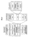
- Fig. 9 shows the details of the conventional communication procedure.
- the basic sequence is the overall processing procedure.
- the location information shows the format of transmission data and composed of point attribute information, data on points 1 through n, and text data.
- the point k information among the sent data shown in Fig. 9 shows details of the point k.
- Detailed point information consists of time data, latitude/longitude information, point-to-point mileage data, and turning data.
- a message type indicating the type of data, basic data or extended data is transmitted as the basic sequence.
- the length of message data is transmitted.
- the body of message data is transmitted.
- the body of message data is composed of a terminal ID consisting of a serial number and telephone number, state information consisting of sensor information, and location information.
- a conventional example of such an on-vehicle terminal is a location information transmitter disclosed in the Japanese Patent Laid-Open No. 18648/1994.
- This apparatus is a location information transmitter that aims at automatically outputting correct location information via simple manipulation and that acquires location information via GPS satellites to output radio waves.
- An on-vehicle terminal measures the current location of the vehicle, and obtains the location information consisting of the latitude, longitude and altitude by using the GPS satellites.
- the on-vehicle terminal assembles the location information, origination start time and recognition code into an origination signal according to the origination signal format.
- the on-vehicle terminal outputs the location information of the originating party with radio wave by modulating the high-frequency carrier with the origination signal.
- US-A-5 808 564 disdoses a personal security system being provided in a vehicle.
- the system collects position information and can be activated by plural emergency push buttons or sensors signaling an accident
- a cellular telephone or a cellular telephone transceiver unit is connected to the personal security system for submitting data specifying the kind of emergency and position information to an emergency center. Further, this system may be activated by a remote unit which indudes a panic button and a push-button RF transmitter.
- emergency center staff may initiate a voice communication mode via a handset provided with the vehicle's cellular telephone system.
- An emergency information system is disclosed in JP-A-11 312285, comprising accident and position detection means. Further, this system comprises a wireless communication device 23 for transmitting emergency data, including cellular telephone unit 32, first transmission device 33 for connecting modem 34 to cellular telephone unit 32, and second transmission device 35 for connecting handset 36 or a hands-free set to cellular telephone unit 32.
- the system may automatically switch from a data transmission mode to a voice mode by operating either first transmission device 33 for data transmission or second transmission device 35 for voice transmission.
- the object of the present invention is to solve the above problems and to provide an on-vehicle communication terminal that assures report to the center as well as safety of the crew.
- the mobile terminal further includes a function of location information detecting means. Owing to this configuration, it is possible to trace the location of the crew who have escaped from the vehicle.
- the on-vehicle communication terminal further includes state sensor means as a function of the mobile terminal. Owing to this configuration, it is possible to monitor the state change of the crew who have escaped from the vehicle.
- the invention according to claim 2 of the present invention provides an on-vehicle communication terminal according to claim 1, wherein the on-vehicle communication terminal further includes means for detecting the relative distance between the on-vehicle terminal and the mobile terminal, and the a main terminal for communications at the on-vehicle communication terminal is switched over. Owing to this configuration, it is possible to constantly follow the mobile terminal by switching over the a main terminal for communications at the on-vehicle communication terminal.
- the invention according to claim 3 of the present invention provides an information service center wherein the information service center comprises means for distinguishing information between the information transmitted from the on-vehicle terminal and the information transmitted from the mobile terminal when the service center receives and restores information transmitted from a plurality of types of on-vehicle communication terminals according to one of claim 1 through claim 5 to location information on each point by using a predetermined communication protocol. Owing to this configuration, it is possible to distinguish between information on the vehicle and information on the crew. Thus it is possible for the center to make safer judgement on the crew who have escaped from the vehicle in the event of an accident or a sudden illness.
- the invention according to claim 4 of the present invention provides an on-vehicle communication terminal including location information detecting means, state sensor means for detecting an abnormal state and outputting the state information, means for recording predetermined location information having time information and latitude/longitude information at each point in the location information obtained by the location information detecting means, an on-vehicle terminal equipped with first radio communication means for transmitting predetermined data having state information, location information and a terminal ID to the information service center on occurrence of a predetermined event, and a mobile terminal equipped with second radio communication means provided with a part of the functions of the on-vehicle terminal detached therefrom, wherein the mobile terminal is provided with data retaining means for temporarily storing data, the data retaining means storing the predetermined data updated as required while the vehicle is traveling.
- An on-vehicle communication terminal includes a configuration in which higher-priority emergency information data to be transmitted to the information service center is stored to the data retaining means and it is possible to take out the emergency information data of the vehicle together with the mobile terminal by storing the emergency information data in the data retaining means in the event of an emergency. Owing to this configuration, it is possible to provide a mobile terminal that secures various data in an accident while reducing the data volume to be taken out of the vehicle in an accident, thus helping determine the cause of the accident, the mobile terminal seldom going faulty with a simple structure.
- An on-vehicle communication terminal has a configuration where the on-vehicle communication terminal, after transmitting the emergency information data to the information service center, makes voice communications with the information service center. Owing to this configuration, it is possible for the center to recognize the distant party via data transmission from the mobile terminal even in case the data in the on-vehicle terminal is corrupted, thus securing report to the center.
- An on-vehicle communication terminal has a configuration where communications from the mobile terminal to the service center are made via communication apparatus different from the on-vehicle terminal associated with the mobile terminal, the communication apparatus existing in the close proximity of the mobile communication terminal. Owing to this configuration, it is possible to reliably report to the center from a nearby substitute communication terminal even in case the associated on-vehicle terminal has failed in communications.
- a numeral 1 designates an on-vehicle terminal, 2 a information service center, 3 a mobile terminal, 10, 20, 30 a CPU, 11 location information detecting means, 12, 21 first radio communication means, 13 an emergency button, 14 a state sensor, 15, 32 a display, 16, 31 second radio communication means, 22 on-vehicle path display function, 23 an operator console display, 24 a map display function, 25 a map database, and 41 data retaining means.
- Fig. 1 is a block diagram of an on-vehicle communication terminal and an information service center according to claim 1.
- the on-vehicle communication terminal is composed of an on-vehicle terminal 1 and a mobile terminal 3.
- the on-vehicle terminal 1 is associated with the mobile terminal 3.
- the on-vehicle terminal 1 includes location information detecting means 11 for obtaining location information by using the GPS and others; first radio communication means 12 for transmitting location information by radio to a center 2, an emergency button 13 for manually starting an emergency report in an emergency, a state sensor 14 for automatically detecting an abnormal state such as an accident or sudden illness and starting an emergency report; second radio communication means 16; a display 15 for displaying the operating state of the on-vehicle terminal 1 and a report to the crew; location information detecting means 11; and a control function unit (hereinafter referred to as the CPU) 10 for controlling the radio communication means.
- the CPU control function unit
- the mobile terminal 3 includes second radio communication means 31; a display 32 for displaying the operating state of the mobile terminal 3 and the report to the crew; and a CPU 30 for controlling radio communication means.
- the first radio communication means 12 of the on-vehicle terminal 1 communicates with first radio communication means 21 in the center 2.
- the second radio communication means 31 of the on-vehicle terminal 1 communicates with the second radio communication means 31 in the mobile terminal 3.
- the information service center 2 includes the first radio communication means 21 for receiving location information transmitted from the on-vehicle terminal 1; an on-vehicle terminal path display function 22 for displaying the path of the on-vehicle terminal 1 on an operator console 23 based on the location information; an operator console display 23 for displaying the travel path of the on-vehicle terminal 1 and state information on a map; a map display function 24 for extracting map data including the travel path of the on-vehicle terminal from a map database 25 and displaying the map data on the operator console 23; and a CPU 20 for controlling the on-vehicle terminal path display function means 22 and radio communication means.
- Fig. 2 is a block diagram of an on-vehicle communication terminal and an information service center according to claim 2.
- the on-vehicle communication terminal is composed of an on-vehicle terminal 1 and a mobile terminal 3.
- the on-vehicle terminal 1 is associated with the mobile terminal 3.
- Fig. 2 is the same as Fig. 1 except that the location information detecting means 11 is placed in the mobile terminal 3 instead of the on-vehicle terminal 1. As a result, it is possible to trace the travel path of the crew when the crew carrying the mobile terminal 3 escape in an emergency.
- Fig. 3 is a block diagram of an on-vehicle communication terminal and an information service center according to claim 3.
- the on-vehicle communication terminal is composed of an on-vehicle terminal 1 and a mobile terminal 3.
- the on-vehicle terminal 1 is associated with the mobile terminal 3.
- Fig. 3 is the same as Fig. 1 except that the state sensor 14 is placed in the mobile terminal 3 instead of the on-vehicle terminal 1. As a result, it is possible to monitor the state change of the crew when the crew carrying the mobile terminal 3 escape in an emergency.
- Fig. 4 shows an example of output timing of various information assumed in the case where communication are made between the on-vehicle terminal 1 and the mobile terminal 3 using the second radio communication means 16 according to an embodiment of the invention.
- Fig. 5 shows an example of data processing method in a mobile terminal according to an embodiment of the invention.
- Fig. 1 Location information is detected by the location information detecting means 11 per predetermined distance, predetermined time or predetermined turning angle, or per combination thereof each time the on-vehicle terminal 1 travels. Then the location information is cyclically stored in a ring buffer (not shown). Information to be stored contains time data, latitude /longitude information on each point, mileage data from the preceding point, and the turning angle from the preceding point.
- the on-vehicle terminal 1 generates a trigger to start emergency report operation on detecting an abnormal state or request by the center 2.
- the on-vehicle terminal 1 adds a terminal ID to location information stored in the ring buffer (not shown) to build send information, and transmits the resulting information to the center 2 via the first radio communication means 12 according to a predetermined communication protocol.
- the center 2 receives location information and a terminal ID from the on-vehicle terminal 1 via the first radio communication means 21.
- the center 2 uses the received terminal ID to check that the owner of the on-vehicle terminal 1 is a member eligible for the services from the center 2, and displays the travel path of the on-vehicle terminal 1 with superposing the digital map displayed on the operator console.
- the on-vehicle terminal 1 after completion of data transmission to the center 2, enters the voice mode.
- the mobile terminal 3 can make voice communications with the operator in the center 2 via the second radio communication means 31 and the second radio communication means 16 in the on-vehicle terminal 1.
- the second radio communication means 16 is typically compact and lightweight and uses a small-power radio wave that allows short-range communications of some tens of meters.
- the Bluetooth system that has recently attracted people's attention is optimum for the invention. It is possible to use other short-range radio communication systems.
- the communication procedure according to claim 1 will be described referring to Fig. 6.
- the communication party at the on-vehicle communication terminal is on-vehicle terminal 1.
- the on-vehicle terminal 1 transmits the message type to represent the basic type or extended type at the beginning of the basic sequence.
- the on-vehicle terminal 1 then transmits the message data length and the message data body.
- the message data body is composed of state information consisting of a serial number, a terminal ID such as a telephone number and sensor information, and location information.
- the communication party at the on-vehicle communication terminal is switched over from the on-vehicle terminal 1 to the mobile terminal 3 when the communication mode changes from data communication mode to voice communication mode. This allows the crew carrying the mobile terminal 3 who have escaped from the vehicle to make voice communication with the operator in the center 2.
- FIG. 4 shows an example of output timing of various information in a mobile terminal assumed in the case where second radio communications are made between the on-vehicle terminal 1 and the mobile terminal 3. While the embodiment according to claim 1 assumes voice communication after finishing data communication, it is possible to multiplex location information and state sensor information from the mobile terminal 3 into a speech signal for transmission in claim 2 through the claim 4.
- the speech signal occupies a space of 64 bits within 1TS.
- the speech signal occupies a space of 64 bits within 1TS.
- This approach is supported by the aforementioned Bluetooth system whose baseband transmission rate is 1 Mbps. This approach is also applicable in other short-range radio communication systems where the baseband transmission rate is sufficient for multiplexing.
- Fig. 5 shows an example of data processing method in a mobile terminal 3 in the multiplex communication.
- signals from location information detecting means 11 such as the GPS, state sensor means 14, a loudspeaker 37 and a microphone 38 undergo location information output processing, sensor information output processing and speech signal output processing respectively and then multiplexing.
- the signals pass through a send/receive buffer register and second radio communication means 31 and are transmitted to the on-vehicle terminal 1 via an antenna 39a.
- the mobile terminal 3 is equipped with the location information detecting means 11 so that only the location information is multiplexed.
- the mobile terminal 3 is equipped with the state sensor 14 so that only the state sensor information is multiplexed.
- While radio wave intensity from the mobile terminal 3 is monitored by using the second radio communication means 16 in the on-vehicle terminal 1 in order to detect the relative distance between the on-vehicle terminal 1 and the mobile terminal 3 and the communication party is typically set to the on-vehicle terminal 1 according to claim 5 as shown in Figs. 1 through 3, it is possible to switch over the communication party to the mobile terminal 3 when the radio wave intensity has dropped below a predetermined value.
- the location information detecting means 11 and the state sensor 14 are illustrated assuming a combination of the on-vehicle terminal 1 and the mobile terminal 3 constitutes a single unit.
- the location information detecting means is separately provided in the on-vehicle terminal and the mobile terminal, since the antenna installation conditions have considerable effects on the characteristics of the location information detecting means.
- the state sensor is preferably provided separately since the detecting conditions of the emergency sensor and accident sensor differ between the vehicle and the crew.
- Fig. 7 is a block diagram of an on-vehicle communication terminal and an information service center according to the embodiment of claim 7 through claim 10.
- the on-vehicle communication terminal is composed of an on-vehicle terminal 1 and a mobile terminal 3.
- the on-vehicle terminal 1 is associated with the mobile terminal 3.
- Fig. 7 is the same as Fig. 1 except that data retaining means 41 is additionally provided in the mobile terminal 3.
- data retaining means 41 is additionally provided in the mobile terminal 3.
- the on-vehicle communication terminal Operation of the on-vehicle communication terminal according to the second embodiment thus configured will be described. First, general operation flow of the entire system will be described referring to Fig. 7.
- location information is detected by the location information detecting means 11 per predetermined range, predetermined time or predetermined turning angle, or per combination thereof each time the on-vehicle terminal 1 travels. Then the location information is cyclically stored in a ring buffer (not shown). Information to be stored contains time data, latitude/longitude information on each point, mileage data from the preceding point, and the turning angle from the preceding point.
- the location information stored in the ring buffer (not shown) in the on-vehicle terminal 1 is simultaneously stored into the data retaining means 41 consisting of memory provided in the mobile terminal 3.
- Location data stored then is preferably same as the data to be stored into the ring buffer and should contain the location data representing the final location.
- State information consisting of sensor information may be added.
- higher-priority emergency information data to be transmitted to the information service center in an emergency is also stored into the data retaining means 41. As a result, it is possible to take out higher-priority emergency information data to be transmitted to the information service center by letting the crew carry the mobile terminal 3 when escaping out of the vehicle in an emergency.
- the emergency information data contains a terminal ID, a vehicle ID (serial number, manufacturer's name), a subscriber ID (member number, originating number of a portable telephone set to which the subscriber registers), location information (location data representing the location in the event of an emergency), time information, and accident information (state sensor information indicating whether the air bag worked and whether the manual button was manipulated).
- the location information may be the same as that stored in the ring buffer in the on-vehicle terminal, as mentioned earlier. It is possible to store the aforementioned whole message data body into the data retaining means 41. Thus it is possible to transmit the message data body from the mobile terminal 3 to the center 2 via the communication procedure shown in Fig. 6 in order to make communications with the center 2.
- the on-vehicle communication terminal supports the following situations that may take place when the crew carrying the mobile terminal 3 have successfully escaped from the vehicle:
- the mobile terminal 3 is equipped with data retaining means 41. It is thus possible to reliably take the information to be transmitted to the information service center out of the vehicle by letting the escaping crew carry the mobile terminal 3.
- the mobile terminal 3 can perform emergency report operation again by the following operation after the crew have escaped.
- the mobile terminal 3 generates a trigger via manipulation by the crew carrying the mobile terminal 3 to perform emergency report operation again.
- the mobile terminal 3 adds a terminal ID to location information stored in the data retaining means 41 to build information to be sent, and tries communications with the on-vehicle terminal 1 associated via the second radio communication means 31 provided in the mobile terminal 3 according to a predetermined communication protocol.
- the mobile terminal 3 undergoes the operation flow and communication procedure shown in Figs. 1 and 6.
- the mobile terminal then completes data transmission to the center 2, enters the voice mode. Now the mobile terminal 3 can make voice communications with the operator in the center 2 via the second radio communication means 31 and the second radio communication means 12 in the on-vehicle terminal 1.
- the repeater provided on the roadside may be a roadside machine used for narrow area communications (called DSRC) covering a narrow area used for roadside-to-vehicle communications such as the ETC (Electronic Toll Collection) system or commercial car management system.
- DSRC narrow area communications
- the DSRC is a type of short-range radio communications and its communication range is several meters to several tens of meters.
- the second radio communication means 31 of the mobile terminal 3 can preferably make narrow-area communications with the roadside machine.
- the roadside machine may be used with a repeater supporting the Bluetooth-based communication in order to relay communications with the center 2.
- the roadside machine can do without a repeater.
- the center 2 In case communications are made with another on-vehicle terminal mounted on another vehicle, it is possible for the center 2 to identify the data transmission from a source other than the associated terminal, by providing originating source information in the header section of the information from the on-vehicle terminal 3.
- the mobile terminal can transmit location information stored in the data retaining means 41 in the mobile terminal 3 as location information to be transmitted as well as transmit location information in another on-vehicle terminal currently in use to the center, since communications are made with the center via another on-vehicle terminal mounted on another vehicle. Accordingly, more accurate location information can be transmitted.
- the mobile terminal retains predetermined data including a terminal ID and location information necessary for establishing communications with the center 2.
- the mobile terminal 3 alone can make communications to the center 2 to secure an emergency report.
- an on-vehicle communication terminal of the present invention various . data in the event of an accident is retained in the mobile terminal 3 even when the on-vehicle terminal 1 is disabled. This helps determine the cause of the accident in the conduct of the accident, as well as secure the safety of the crew. It is possible to provide a mobile terminal that secures various data in an accident while reducing the data volume to be taken out of the vehicle in an accident, thus helping determine the cause of the accident, the mobile terminal seldom going faulty with a simple structure. It is possible for the center to recognize the originating party via data communications from the mobile terminal even in case the data in the mobile terminal has corrupted, thus securing a report to the center.
- an on-vehicle communication terminal for transmitting data including state information, location information and a terminal ID to the information service center, for switching to the voice mode, and for making voice communications with the operator in the information service center, wherein the on-vehicle terminal function is detached using the short-range radio communications and a mobile terminal is provided anew for the crew to carry in escaping from the vehicle in an emergency, in order to secure both safety of the crew and emergency contact.
- the present invention has an excellent effect of securing both contact with the information service center and safety of the crew, by providing second radio communication means and separately configuring a mobile terminal having functions of voice communication, location information detection, state sensor detection, and data retention in order to let the crew escaping from the vehicle carry the mobile terminal in a traffic accident. Further, it is possible to detect travel information and state change information of the crew off the vehicle and report such information to the information service center by using the mobile terminal.
- the mobile terminal By separately providing short-range, low-radio-power second radio communication means, the mobile terminal itself attains a lightweight and compact design which is very convenient for the crew to carry along.
Landscapes
- Physics & Mathematics (AREA)
- General Physics & Mathematics (AREA)
- Engineering & Computer Science (AREA)
- Computer Security & Cryptography (AREA)
- Business, Economics & Management (AREA)
- Emergency Management (AREA)
- Alarm Systems (AREA)
- Mobile Radio Communication Systems (AREA)
- Traffic Control Systems (AREA)
- Telephonic Communication Services (AREA)
Claims (7)
- Ein fahrzeugeigenes Kommunikationsgerät (1, 3) enthaltend
Vorrichtung zur Bestimmung von Positionsinformationen (11);
Zustandssensor-Vorrichtung (14) zum Bestimmen eines anomalen Zustands und Ausgeben von Zustandsinformationen;
Vorrichtung zum Aufzeichnen zuvor bestimmter Positionsinformationen, die Zeitinformationen und Informationen über die geografische Breite/Länge der Positionsinformationen aufweisen, die an jedem Punkt durch die Vorrichtung zur Bestimmung von Positionsinformationen erhalten werden;
eine erste Funkverkehr-Vorrichtung (12) zum Übertragen zuvor bestimmter Daten, welche die Zustandsinformationen, die zuvor bestimmten Positionsinformationen und eine Datenendgerät-ID beinhalten, an eine Informationsservicezentrale (2) bei Eintreten eines vorherbestimmen Ereignisses; und
eine Sprachkommunikations-Vorrichtung (31, 37, 38, 16);
wobei das genannte fahrzeugeigene Kommunikationsgerät umfasst
ein fahrzeugeigenes Datenendgerät (1); und
ein mobiles Datenendgerät (3), welches von dem genannten fahrzeugeigenen Datenendgerät (1) abnehmbar ist, und das über das genannte fahrzeugeigene Datenendgerät (1) zu der Kommunikation mit einer Informationsservicezentrale (2) fähig ist, dadurch gekennzeichnet dass
wenn ein vorherbestimmtes Ereignis eintritt und ein Benutzer das genannte Fahrzeug mit dem genannten mobilen Datenendgerät (3), das vollständig von dem genannten fahrzeugeigenen Datenendgerät (1) abgenommen wurde, verlässt,
das genannte fahrzeugeigene Datenendgerät (1) automatisch der genannten Informationsservicezentrale (2) mithilfe einer ersten Funkverkehr-Vorrichtung (12) den Zustand, die Position und die Identifikationsdaten zum Identifizieren sowohl des genannten fahrzeugeigenen Datenendgeräts (1) als auch des genannten mobilen Datenendgeräts (3) mitteilt, und
nach der Beendigung des Übertragens des Zustands, der Position und der Identifikationsdaten zu der genannten Informationsservicezentrale (2) das genannte mobile Datenendgerät (3) automatisch eine Sprachkommunikation mit der genannten Informationsservicezentrale (2) über das genannte fahrzeugeigene Datenendgerät (1) startet; und
worin die genannte Sprachkommunikation in der Weise hergestellt wird, dass:das genannte mobile Datenendgerät (3) Audiodaten von einer zweiten Funkverkehr-Vorrichtung (31) des genannten mobilen Datenendgeräts (3) zu einer anderen zweiten Funkverkehr-Vorrichtung (16) des genannten fahrzeugeigenen Datenendgeräts (1) überträgt; unddas genannte fahrzeugeigene Datenendgerät (1) die genannten Audiodaten durch die zweite Funkverkehr-Vorrichtung (16) des genannten fahrzeugeigenen Datenendgeräts (1) empfängt, die genannten Audiodaten zu einer ersten Funkverkehr-Vorrichtung (12) des genannten fahrzeugeigenen Datenendgeräts (1) weiterleitet und sodann die genannten Audiodaten von einer ersten Funkverkehr-Vorrichtung (12) des genannten fahrzeugeigenen Datenendgeräts (1) zu einer anderen ersten Funkverkehr-Vorrichtung (21) der genannten Informationsservicezentrale (2) überträgt. - Ein fahrzeugeigenes Kommunikationsgerät nach Anspruch 1, dadurch gekennzeichnet dass
die genannte andere zweite Funkverkehr-Vorrichtung (16) dazu geeignet ist, die Wellenintensität zu überwachen, um den Abstand des mobilen Datenendgeräts (3) von dem Fahrzeug zu bestimmen und die Kommunikation zwischen dem mobilen Datenendgerät (3) und dem fahrzeugeigenen Datenendgerät (1) zu ermöglichen, wenn die Funkwellenintensität unter einen vorherbestimmten Wert gefallen ist. - Eine Informationsservicezentrale umfassend:eine Vorrichtung zum Unterscheiden von Informationen danach, ob die Informationen von dem genannten fahrzeugeigenen Datenendgerät (1) oder die Informationen von dem genannten mobilen Datenendgerät (3) übertragen werden, wenn die genannte Informationsservicezentrale (2) Informationen zu Positionsinformationen von jedem Punkt gemäß einem vorherbestimmten Kommunikationsprotokoll, die von einer Vielzahl von Arten von fahrzeugeigenen Kommunikationssystemen nach Anspruch 1 oder 2 übertragen werden, empfängt und speichert.
- Das fahrzeugeigene Kommunikationsgerät nach einem der Ansprüche 1 bis 3,
worin das genannte mobile Datenendgerät (3) eine Vorrichtung zum Speichern von Daten (41) zum temporären Speichern von Daten enthält, und
worin die Vorrichtung zum Speichern von Daten temporär Daten speichert, die aktualisiert werden, wenn es, während das Fahrzeug sich bewegt, notwendig ist. - Das fahrzeugeigene Kommunikationsgerät nach Anspruch 4,
worin die genannte Vorrichtung zum Speichern von Daten (41) Notfall-Informationsdaten mit höherer Priorität, die an die Informationsservicezentrale (2) übertragen werden sollen, speichert, und die Notfall-Informationsdaten, die in der Vorrichtung zum Speichern von Daten gespeichert sind, zusammen mit dem genannten mobilen Datenendgerät (3) in einem Notfall aus dem Fahrzeug entnommen werden können. - Das fahrzeugeigene Kommunikationsgerät nach Anspruch 5,
worin das genannte fahrzeugeigene Kommunikationssystem mit der Informationsservicezentrale (2) nach dem Übertragen der Notfall-Informationsdaten zu der Informationsservicezentrale (2) von dem genannten mobilen Datenendgerät (3) eine Sprachkommunikation unterhält. - Das fahrzeugeigene Kommunikationsgerät nach Anspruch 6, worin die Kommunikation von dem genannten mobilen Datenendgerät (3) zu der Servicezentrale (2) über ein Kommunikationsgerät unterhalten wird, das von dem fahrzeugeigenen Datenendgerät (1) verschieden ist, und das ein Kommunikationsgerät, das sich in der Nähe des mobilen Datenendgeräts (3) befindet, zum Beispiel eine Übertragungseinrichtung am Straßenrand oder ein anderes fahrzeugeigenes Datenendgerät, das in einem anderen Fahrzeug angebracht ist, oder ein straßenseitiges Gerät (DSRC), sein kann.
Applications Claiming Priority (3)
| Application Number | Priority Date | Filing Date | Title |
|---|---|---|---|
| JP32294199 | 1999-11-12 | ||
| JP32294199 | 1999-11-12 | ||
| PCT/JP2000/007964 WO2001037240A1 (en) | 1999-11-12 | 2000-11-10 | On-board communication terminal and information service center communicating with on-board communication terminal |
Publications (3)
| Publication Number | Publication Date |
|---|---|
| EP1143400A1 EP1143400A1 (de) | 2001-10-10 |
| EP1143400A4 EP1143400A4 (de) | 2002-04-17 |
| EP1143400B1 true EP1143400B1 (de) | 2005-02-23 |
Family
ID=18149356
Family Applications (1)
| Application Number | Title | Priority Date | Filing Date |
|---|---|---|---|
| EP00974935A Expired - Lifetime EP1143400B1 (de) | 1999-11-12 | 2000-11-10 | Bordkommunikationsendgerät und informationsversorgungszentrum für dieses endgerät |
Country Status (5)
| Country | Link |
|---|---|
| US (1) | US7200409B1 (de) |
| EP (1) | EP1143400B1 (de) |
| JP (1) | JP3300705B2 (de) |
| DE (1) | DE60018263T2 (de) |
| WO (1) | WO2001037240A1 (de) |
Cited By (2)
| Publication number | Priority date | Publication date | Assignee | Title |
|---|---|---|---|---|
| CN108886556A (zh) * | 2016-06-07 | 2018-11-23 | 马自达汽车株式会社 | 紧急通报装置 |
| CN110070890A (zh) * | 2018-01-24 | 2019-07-30 | 宝沃汽车(中国)有限公司 | 音频处理方法、系统和汽车 |
Families Citing this family (71)
| Publication number | Priority date | Publication date | Assignee | Title |
|---|---|---|---|---|
| US8965677B2 (en) | 1998-10-22 | 2015-02-24 | Intelligent Technologies International, Inc. | Intra-vehicle information conveyance system and method |
| US8255144B2 (en) * | 1997-10-22 | 2012-08-28 | Intelligent Technologies International, Inc. | Intra-vehicle information conveyance system and method |
| US8060389B2 (en) | 2000-06-07 | 2011-11-15 | Apple Inc. | System and method for anonymous location based services |
| US8073565B2 (en) | 2000-06-07 | 2011-12-06 | Apple Inc. | System and method for alerting a first mobile data processing system nearby a second mobile data processing system |
| US6456234B1 (en) * | 2000-06-07 | 2002-09-24 | William J. Johnson | System and method for proactive content delivery by situation location |
| JP4516707B2 (ja) * | 2001-07-10 | 2010-08-04 | 株式会社エヌ・ティ・ティ・ドコモ | ネットワーク制御装置、移動通信システム及び移動通信ネットワーク制御方法 |
| DE10155550C1 (de) * | 2001-11-12 | 2003-10-02 | Harman Becker Automotive Sys | Verfahren und Notrufeinrichtung zur Auslösung eines Notrufs von einem Fahrzeug |
| US6493629B1 (en) * | 2001-12-03 | 2002-12-10 | Motorola, Inc. | Method of and system for coupling location information |
| WO2004008411A1 (en) * | 2002-07-11 | 2004-01-22 | Nokia Corporation | Method and device for automatically changing a digital content on a mobile device according to sensor data |
| JP4076071B2 (ja) * | 2002-08-19 | 2008-04-16 | アルパイン株式会社 | 移動体間の通信方法及び車両通信装置 |
| JP4236916B2 (ja) * | 2002-11-29 | 2009-03-11 | 綜合警備保障株式会社 | 位置情報監視システム、位置情報監視方法 |
| DE602004016324D1 (de) * | 2003-05-26 | 2008-10-16 | Securecom Technologies Ltd | Tragbare kommunikationsvorrichtung |
| TW200500965A (en) * | 2003-06-17 | 2005-01-01 | Sin Etke Technology Co Ltd | Personal carry-on rescue system |
| DE10338759A1 (de) | 2003-08-23 | 2005-03-17 | Daimlerchrysler Ag | Vorrichtung eines Kraftfahrzeuges zur Bereitstellung unfallbezogener Daten |
| US8130697B1 (en) * | 2004-02-03 | 2012-03-06 | Genx Mobile, Inc. | Autonomous mobile electronic mail system |
| US7353034B2 (en) | 2005-04-04 | 2008-04-01 | X One, Inc. | Location sharing and tracking using mobile phones or other wireless devices |
| DE102007017143A1 (de) * | 2007-04-11 | 2008-10-16 | Arkadij Gershman | Verfahren zur Objektortung und Routeführung |
| US8290513B2 (en) | 2007-06-28 | 2012-10-16 | Apple Inc. | Location-based services |
| US8311526B2 (en) | 2007-06-28 | 2012-11-13 | Apple Inc. | Location-based categorical information services |
| US8175802B2 (en) | 2007-06-28 | 2012-05-08 | Apple Inc. | Adaptive route guidance based on preferences |
| US8332402B2 (en) | 2007-06-28 | 2012-12-11 | Apple Inc. | Location based media items |
| US9066199B2 (en) | 2007-06-28 | 2015-06-23 | Apple Inc. | Location-aware mobile device |
| US8108144B2 (en) | 2007-06-28 | 2012-01-31 | Apple Inc. | Location based tracking |
| US8385946B2 (en) | 2007-06-28 | 2013-02-26 | Apple Inc. | Disfavored route progressions or locations |
| US8774825B2 (en) | 2007-06-28 | 2014-07-08 | Apple Inc. | Integration of map services with user applications in a mobile device |
| US9109904B2 (en) | 2007-06-28 | 2015-08-18 | Apple Inc. | Integration of map services and user applications in a mobile device |
| US8204684B2 (en) | 2007-06-28 | 2012-06-19 | Apple Inc. | Adaptive mobile device navigation |
| US8762056B2 (en) | 2007-06-28 | 2014-06-24 | Apple Inc. | Route reference |
| US8180379B2 (en) * | 2007-06-28 | 2012-05-15 | Apple Inc. | Synchronizing mobile and vehicle devices |
| US8275352B2 (en) | 2007-06-28 | 2012-09-25 | Apple Inc. | Location-based emergency information |
| DE102008008371A1 (de) * | 2007-12-06 | 2009-06-25 | Continental Teves Ag & Co. Ohg | Verfahren und System zum Absetzen eines Notrufs |
| US8355862B2 (en) | 2008-01-06 | 2013-01-15 | Apple Inc. | Graphical user interface for presenting location information |
| EP2266091A4 (de) * | 2008-03-17 | 2012-11-21 | Intelligent Mechatronic Sys | Strassenrand- und notfallhilfssystem |
| US9250092B2 (en) | 2008-05-12 | 2016-02-02 | Apple Inc. | Map service with network-based query for search |
| US8644843B2 (en) | 2008-05-16 | 2014-02-04 | Apple Inc. | Location determination |
| DE102008028975B4 (de) * | 2008-06-18 | 2020-11-26 | Bayerische Motoren Werke Aktiengesellschaft | Kraftfahrzeug |
| US8369867B2 (en) | 2008-06-30 | 2013-02-05 | Apple Inc. | Location sharing |
| US8274405B2 (en) * | 2008-09-03 | 2012-09-25 | GM Global Technology Operations LLC | System and method for device management on a dedicated short-range communication network |
| US8359643B2 (en) | 2008-09-18 | 2013-01-22 | Apple Inc. | Group formation using anonymous broadcast information |
| US8260320B2 (en) | 2008-11-13 | 2012-09-04 | Apple Inc. | Location specific content |
| US8670748B2 (en) | 2009-05-01 | 2014-03-11 | Apple Inc. | Remotely locating and commanding a mobile device |
| US8666367B2 (en) | 2009-05-01 | 2014-03-04 | Apple Inc. | Remotely locating and commanding a mobile device |
| US8660530B2 (en) | 2009-05-01 | 2014-02-25 | Apple Inc. | Remotely receiving and communicating commands to a mobile device for execution by the mobile device |
| US9978272B2 (en) * | 2009-11-25 | 2018-05-22 | Ridetones, Inc | Vehicle to vehicle chatting and communication system |
| WO2011145344A1 (ja) * | 2010-05-18 | 2011-11-24 | 三洋電機株式会社 | 基地局装置 |
| US8718536B2 (en) | 2011-01-18 | 2014-05-06 | Marwan Hannon | Apparatus, system, and method for detecting the presence and controlling the operation of mobile devices within a vehicle |
| US8686864B2 (en) | 2011-01-18 | 2014-04-01 | Marwan Hannon | Apparatus, system, and method for detecting the presence of an intoxicated driver and controlling the operation of a vehicle |
| JP4729137B1 (ja) * | 2011-03-03 | 2011-07-20 | 株式会社データ・テック | 移動体に搭載される運行管理装置、携帯情報端末、運行管理サーバ、コンピュータプログラム |
| US10041798B2 (en) | 2012-12-06 | 2018-08-07 | Qualcomm Incorporated | Determination of position, velocity and/or heading by simultaneous use of on-device and on-vehicle information |
| US20160240081A1 (en) * | 2013-09-24 | 2016-08-18 | Data Mining Innovators B.V. | Geographic Based Location System Arranged For Providing, Via A Web-Based Portal, Management Information Of Geographic Data And Non-Geographic Data Generated By A Plurality Of Wireless Communication Devices, And A Related Method |
| JP6191367B2 (ja) * | 2013-09-30 | 2017-09-06 | トヨタ自動車株式会社 | 安否情報伝達方法および安否情報伝達システム |
| JP6305100B2 (ja) * | 2014-02-21 | 2018-04-04 | 本田技研工業株式会社 | 緊急通報システム |
| DE102014212990A1 (de) | 2014-07-04 | 2016-01-07 | Bayerische Motoren Werke Aktiengesellschaft | Herstellen einer Sprachverbindung zwischen dem Fahrer eines einspurigen Fahrzeugs und einer Notrufzentrale |
| AU2016294604A1 (en) | 2015-07-14 | 2018-03-08 | Driving Management Systems, Inc. | Detecting the location of a phone using RF wireless and ultrasonic signals |
| US9785150B2 (en) | 2015-12-11 | 2017-10-10 | Uber Technologies, Inc. | Formatting sensor data for use in autonomous vehicle communications platform |
| US9596666B1 (en) | 2015-12-11 | 2017-03-14 | Uber Technologies, Inc. | System for processing asynchronous sensor data |
| US9537956B1 (en) * | 2015-12-11 | 2017-01-03 | Uber Technologies, Inc. | System for acquiring time-synchronized sensor data |
| US10101747B2 (en) | 2015-12-11 | 2018-10-16 | Uber Technologies, Inc. | Formatting sensor data for use in autonomous vehicle communications platform |
| US10114103B2 (en) | 2016-03-31 | 2018-10-30 | Uber Technologies, Inc. | System and method for sensor triggering for synchronized operation |
| JP6528975B2 (ja) * | 2016-04-19 | 2019-06-12 | マツダ株式会社 | 緊急通報装置及び緊急通報システム |
| DE102016006382B4 (de) * | 2016-05-24 | 2024-09-05 | Audi Ag | Verfahren zum Betrieb einer Notrufeinrichtung für ein Kraftfahrzeug und zugehöriges Kraftfahrzeug |
| JP6742063B2 (ja) * | 2016-09-28 | 2020-08-19 | 日立建機株式会社 | 移動体の相互監視システム |
| US10482559B2 (en) | 2016-11-11 | 2019-11-19 | Uatc, Llc | Personalizing ride experience based on contextual ride usage data |
| CN109104536A (zh) * | 2017-06-20 | 2018-12-28 | 重庆无线绿洲通信技术有限公司 | 一种车载终端以及告警管理服务器 |
| JP7458265B2 (ja) * | 2020-07-31 | 2024-03-29 | 株式会社Subaru | 自動通報機能を有する車両 |
| DE102020126198A1 (de) | 2020-10-07 | 2022-04-07 | Bayerische Motoren Werke Aktiengesellschaft | Verfahren und System für eine Anrufübergabe von einem Fortbewegungsmittel an ein mobiles Endgerät |
| DE102022116171A1 (de) | 2021-07-21 | 2023-01-26 | Subaru Corporation | Fahrzeug mit notfallberichtsfunktion, und server |
| JP7767849B2 (ja) * | 2021-11-12 | 2025-11-12 | トヨタ自動車株式会社 | 無線通信システム、無線通信方法及びプログラム |
| KR102418566B1 (ko) * | 2021-12-22 | 2022-07-08 | 재단법인 지능형자동차부품진흥원 | 엣지 인프라 기반의 자율 주행 안전 제어 시스템 및 방법 |
| GB2617115B (en) * | 2022-03-30 | 2025-02-05 | Jaguar Land Rover Ltd | Vehicle positioning |
| IL301573A (en) * | 2023-03-22 | 2024-12-01 | Elta Systems Ltd | Satcom terminal and method for conveying inherent command and control data to a receiving node |
Family Cites Families (14)
| Publication number | Priority date | Publication date | Assignee | Title |
|---|---|---|---|---|
| US5808564A (en) * | 1992-02-06 | 1998-09-15 | Simms Security Corp. | Personal security system with remote activation |
| US5223844B1 (en) * | 1992-04-17 | 2000-01-25 | Auto Trac Inc | Vehicle tracking and security system |
| JPH0618648A (ja) | 1992-07-01 | 1994-01-28 | Fujitsu Ltd | 位置情報発信装置 |
| US5311197A (en) * | 1993-02-01 | 1994-05-10 | Trimble Navigation Limited | Event-activated reporting of vehicle location |
| AU7067394A (en) * | 1993-06-21 | 1995-01-17 | Elke Van Buren | System for summoning help for vehicle occupants or other people carrying a mobile telephone |
| US5572204A (en) * | 1995-04-10 | 1996-11-05 | Ford Motor Company | Vehicular emergency message system |
| US5764736A (en) * | 1995-07-20 | 1998-06-09 | National Semiconductor Corporation | Method for switching between a data communication session and a voice communication session |
| US6519463B2 (en) * | 1996-02-28 | 2003-02-11 | Tendler Cellular, Inc. | Location based service request system |
| US5914675A (en) * | 1996-05-23 | 1999-06-22 | Sun Microsystems, Inc. | Emergency locator device transmitting location data by wireless telephone communications |
| DE19755075A1 (de) * | 1997-12-11 | 1999-06-17 | Joerg Guenther Wittwer | Mobiles Alarm- und Notrufsystem (MAS), basierend auf GPS-Technik (Navigation) und (GSM)-Mobilfunkeinheit |
| JPH11220775A (ja) | 1998-01-29 | 1999-08-10 | Osami Tsutsui | 移動通信端末を用いた緊急通信システム |
| JP3288640B2 (ja) * | 1998-02-27 | 2002-06-04 | 松下電器産業株式会社 | データ/音声の同時通信または通信切替え可能な事故緊急通報システム |
| JP2000311283A (ja) | 1999-04-27 | 2000-11-07 | Alpine Electronics Inc | 通報システムにおけるデータ送信装置 |
| US6298306B1 (en) * | 1999-07-28 | 2001-10-02 | Motorola, Inc. | Vehicle locating system utilizing global positioning |
-
2000
- 2000-11-10 EP EP00974935A patent/EP1143400B1/de not_active Expired - Lifetime
- 2000-11-10 DE DE60018263T patent/DE60018263T2/de not_active Expired - Lifetime
- 2000-11-10 WO PCT/JP2000/007964 patent/WO2001037240A1/ja not_active Ceased
- 2000-11-10 US US09/889,086 patent/US7200409B1/en not_active Expired - Fee Related
- 2000-11-10 JP JP2001539256A patent/JP3300705B2/ja not_active Expired - Fee Related
Cited By (4)
| Publication number | Priority date | Publication date | Assignee | Title |
|---|---|---|---|---|
| CN108886556A (zh) * | 2016-06-07 | 2018-11-23 | 马自达汽车株式会社 | 紧急通报装置 |
| CN108886556B (zh) * | 2016-06-07 | 2021-06-22 | 马自达汽车株式会社 | 紧急通报装置 |
| CN110070890A (zh) * | 2018-01-24 | 2019-07-30 | 宝沃汽车(中国)有限公司 | 音频处理方法、系统和汽车 |
| CN110070890B (zh) * | 2018-01-24 | 2021-05-14 | 宝沃汽车(中国)有限公司 | 音频处理方法、系统和汽车 |
Also Published As
| Publication number | Publication date |
|---|---|
| EP1143400A4 (de) | 2002-04-17 |
| EP1143400A1 (de) | 2001-10-10 |
| JP3300705B2 (ja) | 2002-07-08 |
| DE60018263T2 (de) | 2005-08-25 |
| WO2001037240A1 (en) | 2001-05-25 |
| DE60018263D1 (de) | 2005-03-31 |
| US7200409B1 (en) | 2007-04-03 |
Similar Documents
| Publication | Publication Date | Title |
|---|---|---|
| EP1143400B1 (de) | Bordkommunikationsendgerät und informationsversorgungszentrum für dieses endgerät | |
| JPWO2001037240A1 (ja) | 車載通信端末および車載通信端末と通信する情報サービスセンタ | |
| US11665500B2 (en) | System and method for improving telematics location information and reliability of E911 calls | |
| US7580697B2 (en) | Method and emergency call device for triggering an emergency call from a vehicle | |
| US20140024334A1 (en) | Method and System for Emergency Notification | |
| US7289786B2 (en) | Method and apparatus for communicating emergency information using wireless devices | |
| US7822391B1 (en) | Mobile station emergency beacon system | |
| JP3126311U (ja) | 個人携帯型救援要請システム | |
| KR101072946B1 (ko) | 응급 요원들에게 차량 비상상황을 통보하기 위한 경보를생성하는 장치, 및 관련 방법 | |
| US6950020B2 (en) | Surveillance system, method of remotely controlling sensor apparatus, and surveillance remote controller | |
| CN102388633A (zh) | 紧急数据通信的车辆内系统(ivs)控制 | |
| US20050090226A1 (en) | Emergency call system | |
| CN107277791B (zh) | 用于传递关于紧急情况的信息的方法 | |
| JP4107777B2 (ja) | 車両緊急通報システム | |
| JP2001118175A (ja) | 緊急通報システムおよびその車載装置 | |
| CN111161518A (zh) | 一种交通事故报警系统及其自动报警方法 | |
| JP3323158B2 (ja) | 事故通報システムおよび事故通報方法 | |
| JP2001093069A (ja) | 車両間連携による緊急通報システム | |
| JP2001141466A (ja) | 事故通知表示システム及び事故通知装置 | |
| JP2002063672A (ja) | 車両走行軌跡表示システム | |
| JPH08195975A (ja) | セルラー移動局およびそれを用いるセルラー通信システム | |
| KR19990081431A (ko) | 차량사고 자동 전송장치 | |
| JPH1070620A (ja) | 車載情報通信装置 | |
| JPH11285076A (ja) | 移動体用緊急通報装置及び媒体 | |
| US20070270156A9 (en) | Position communication method and apparatus |
Legal Events
| Date | Code | Title | Description |
|---|---|---|---|
| PUAI | Public reference made under article 153(3) epc to a published international application that has entered the european phase |
Free format text: ORIGINAL CODE: 0009012 |
|
| 17P | Request for examination filed |
Effective date: 20010712 |
|
| AK | Designated contracting states |
Kind code of ref document: A1 Designated state(s): AT BE CH CY DE DK ES FI FR GB GR IE IT LI LU MC NL PT SE TR |
|
| AX | Request for extension of the european patent |
Free format text: AL;LT;LV;MK;RO;SI |
|
| A4 | Supplementary search report drawn up and despatched |
Effective date: 20020304 |
|
| AK | Designated contracting states |
Kind code of ref document: A4 Designated state(s): AT BE CH CY DE DK ES FI FR GB GR IE IT LI LU MC NL PT SE TR |
|
| RIC1 | Information provided on ipc code assigned before grant |
Free format text: 7G 01S 5/14 A, 7G 08B 25/10 B, 7H 04B 7/26 B |
|
| 17Q | First examination report despatched |
Effective date: 20021113 |
|
| RBV | Designated contracting states (corrected) |
Designated state(s): DE FR GB |
|
| GRAP | Despatch of communication of intention to grant a patent |
Free format text: ORIGINAL CODE: EPIDOSNIGR1 |
|
| GRAS | Grant fee paid |
Free format text: ORIGINAL CODE: EPIDOSNIGR3 |
|
| GRAA | (expected) grant |
Free format text: ORIGINAL CODE: 0009210 |
|
| AK | Designated contracting states |
Kind code of ref document: B1 Designated state(s): DE FR GB |
|
| REG | Reference to a national code |
Ref country code: GB Ref legal event code: FG4D |
|
| REG | Reference to a national code |
Ref country code: IE Ref legal event code: FG4D |
|
| REF | Corresponds to: |
Ref document number: 60018263 Country of ref document: DE Date of ref document: 20050331 Kind code of ref document: P |
|
| ET | Fr: translation filed | ||
| PLBE | No opposition filed within time limit |
Free format text: ORIGINAL CODE: 0009261 |
|
| STAA | Information on the status of an ep patent application or granted ep patent |
Free format text: STATUS: NO OPPOSITION FILED WITHIN TIME LIMIT |
|
| 26N | No opposition filed |
Effective date: 20051124 |
|
| REG | Reference to a national code |
Ref country code: GB Ref legal event code: 746 Effective date: 20091221 |
|
| PGFP | Annual fee paid to national office [announced via postgrant information from national office to epo] |
Ref country code: DE Payment date: 20091105 Year of fee payment: 10 |
|
| PGFP | Annual fee paid to national office [announced via postgrant information from national office to epo] |
Ref country code: GB Payment date: 20091104 Year of fee payment: 10 Ref country code: FR Payment date: 20091123 Year of fee payment: 10 |
|
| GBPC | Gb: european patent ceased through non-payment of renewal fee |
Effective date: 20101110 |
|
| REG | Reference to a national code |
Ref country code: FR Ref legal event code: ST Effective date: 20110801 |
|
| REG | Reference to a national code |
Ref country code: DE Ref legal event code: R119 Ref document number: 60018263 Country of ref document: DE Effective date: 20110601 Ref country code: DE Ref legal event code: R119 Ref document number: 60018263 Country of ref document: DE Effective date: 20110531 |
|
| PG25 | Lapsed in a contracting state [announced via postgrant information from national office to epo] |
Ref country code: DE Free format text: LAPSE BECAUSE OF NON-PAYMENT OF DUE FEES Effective date: 20110531 |
|
| PG25 | Lapsed in a contracting state [announced via postgrant information from national office to epo] |
Ref country code: FR Free format text: LAPSE BECAUSE OF NON-PAYMENT OF DUE FEES Effective date: 20101130 |
|
| PG25 | Lapsed in a contracting state [announced via postgrant information from national office to epo] |
Ref country code: GB Free format text: LAPSE BECAUSE OF NON-PAYMENT OF DUE FEES Effective date: 20101110 |