EP1143425A2 - Magnetische Übertragungsmethode und -gerät - Google Patents
Magnetische Übertragungsmethode und -gerät Download PDFInfo
- Publication number
- EP1143425A2 EP1143425A2 EP00128742A EP00128742A EP1143425A2 EP 1143425 A2 EP1143425 A2 EP 1143425A2 EP 00128742 A EP00128742 A EP 00128742A EP 00128742 A EP00128742 A EP 00128742A EP 1143425 A2 EP1143425 A2 EP 1143425A2
- Authority
- EP
- European Patent Office
- Prior art keywords
- magnetic
- magnetic field
- slave medium
- transfer
- track direction
- Prior art date
- Legal status (The legal status is an assumption and is not a legal conclusion. Google has not performed a legal analysis and makes no representation as to the accuracy of the status listed.)
- Withdrawn
Links
Images

Classifications
-
- G—PHYSICS
- G11—INFORMATION STORAGE
- G11B—INFORMATION STORAGE BASED ON RELATIVE MOVEMENT BETWEEN RECORD CARRIER AND TRANSDUCER
- G11B5/00—Recording by magnetisation or demagnetisation of a record carrier; Reproducing by magnetic means; Record carriers therefor
- G11B5/86—Re-recording, i.e. transcribing information from one magnetisable record carrier on to one or more similar or dissimilar record carriers
-
- G—PHYSICS
- G11—INFORMATION STORAGE
- G11B—INFORMATION STORAGE BASED ON RELATIVE MOVEMENT BETWEEN RECORD CARRIER AND TRANSDUCER
- G11B5/00—Recording by magnetisation or demagnetisation of a record carrier; Reproducing by magnetic means; Record carriers therefor
- G11B5/86—Re-recording, i.e. transcribing information from one magnetisable record carrier on to one or more similar or dissimilar record carriers
- G11B5/865—Re-recording, i.e. transcribing information from one magnetisable record carrier on to one or more similar or dissimilar record carriers by contact "printing"
-
- G—PHYSICS
- G11—INFORMATION STORAGE
- G11B—INFORMATION STORAGE BASED ON RELATIVE MOVEMENT BETWEEN RECORD CARRIER AND TRANSDUCER
- G11B5/00—Recording by magnetisation or demagnetisation of a record carrier; Reproducing by magnetic means; Record carriers therefor
- G11B5/74—Record carriers characterised by the form, e.g. sheet shaped to wrap around a drum
- G11B5/82—Disk carriers
-
- G—PHYSICS
- G11—INFORMATION STORAGE
- G11B—INFORMATION STORAGE BASED ON RELATIVE MOVEMENT BETWEEN RECORD CARRIER AND TRANSDUCER
- G11B5/00—Recording by magnetisation or demagnetisation of a record carrier; Reproducing by magnetic means; Record carriers therefor
- G11B5/48—Disposition or mounting of heads or head supports relative to record carriers ; arrangements of heads, e.g. for scanning the record carrier to increase the relative speed
- G11B5/58—Disposition or mounting of heads or head supports relative to record carriers ; arrangements of heads, e.g. for scanning the record carrier to increase the relative speed with provision for moving the head for the purpose of maintaining alignment of the head relative to the record carrier during transducing operation, e.g. to compensate for surface irregularities of the latter or for track following
- G11B5/596—Disposition or mounting of heads or head supports relative to record carriers ; arrangements of heads, e.g. for scanning the record carrier to increase the relative speed with provision for moving the head for the purpose of maintaining alignment of the head relative to the record carrier during transducing operation, e.g. to compensate for surface irregularities of the latter or for track following for track following on disks
- G11B5/59633—Servo formatting
Definitions
- the present invention relates to a method for recording a large amount of information on a magnetic recording medium at one time, and in particular, to a method for transferring a recording information to a magnetic recording medium of large capacity and high recording density.
- a large capacity magnetic recording medium such as a hard disk or a removable type magnetic recording medium
- servo signal for tracking or address information signal, reproduction clock signal, etc. are recorded with a certain spacing between them within one turn of the disk. This is the so-called pre-format.
- the magnetic head By reading this pre-formatted signal and by correcting its own position, the magnetic head can run accurately on the track.
- the surface of the projected portions of the master carrier for magnetic transfer is brought closely together to the magnetic recording medium to be pre-formatted, i.e. the slave medium, and the ferromagnetic material which constitutes the projected portions is excited.
- the desired format is formed on the slave medium.
- recording can be carried out statically without changing relative positions of the master carrier for magnetic transfer and the slave medium, and accurate pre-format recording can be performed.
- the time required for the recording is very short. Specifically, in the method for recording from the magnetic head as described above, the time of several minutes to several tens of minutes is normally required, while magnetic transfer can be completed within one second regardless of the recording capacity or recording density in this magnetic transfer method.
- Fig. 1 (A) is a schematical plan view to explain magnetic layer surface of the master carrier for magnetic transfer
- Fig. 1 (B) is a cross-sectional view to explain the process of transfer.
- a pre-format region 2 and a data region 3 where patterns of servo signals and address signal for tracking to be transferred are formed.
- the pre-format information can be transferred to the slave medium as a recording information 7.
- the slave medium can be manufactured with high efficiency.
- the present invention provides a method for magnetic transfer by bringing a master carrier for magnetic transfer with a slave medium and by applying magnetic field for transfer, said master carrier having a magnetic layer on surface of a substrate corresponding to an information signal, and said slave medium comprising a magnetic recording medium where the information is to be transferred, said method comprising the steps of:
- the present invention provides a method for magnetic transfer by bringing a master carrier for magnetic transfer with a slave medium and by applying magnetic field for transfer, said master carrier having a magnetic layer on surface of a substrate corresponding to an information signal, and said slave medium comprising a magnetic recording medium where the information is to be transferred, said method comprising the steps of:
- the present invention provides a method for magnetic transfer as described above, wherein, when said permanent magnets each having magnetic field symmetrical to the axis of the magnetic pole are arranged at least on one of upper or lower surfaces of the slave medium with the axis of the magnetic pole running in parallel to the surface of the slave medium, the magnetic field intensity distribution in track direction of the magnetic field generated is such that there is at least one point where the magnetic field intensity is higher than the coercive force Hcs of the slave medium on a position in track direction.
- the present invention provides a method for magnetic transfer as described above, wherein, when said permanent magnets each having magnetic field symmetrical to the axis of the magnetic pole are arranged at least on one of upper or lower surfaces of the slave medium with the axis of the magnetic pole running in parallel to the surface of the slave medium, the magnetic field intensity distribution in track direction of the magnetic field generated is such that magnetic field intensity higher than the coercive force Hcs of the slave medium is present only in one direction on a position in track direction, and the magnetic field intensity in reverse direction is lower than the coercive force Hcs of the slave medium at any position in any track direction.
- the present invention provides a method for magnetic transfer as described above, wherein, when said permanent magnets each having magnetic field symmetrical to the axis of the magnetic pole are arranged at least on one of upper or lower surfaces of the slave medium with the axis of the magnetic pole running in parallel to the surface of the slave medium, the magnetic field intensity distribution in track direction of the magnetic field generated is such that magnetic field intensity higher than the maximum value of the optimal transfer magnetic field intensity range is not present at any position in any track direction, magnetic field intensity within the optimal transfer magnetic field intensity range is present at least at one point in one track direction, and magnetic field intensity in track direction reverse thereto is lower than the minimum value of the optimal transfer magnetic field intensity range at any position in any track direction.
- the present invention provides a method for magnetic transfer as described above, wherein the optimal transfer magnetic field intensity is 0.6 x Hcs to 1.3 x Hcs with respect to the coercive force Hcs of the slave medium.
- the present invention provides an apparatus for magnetic transfer by bringing a master carrier for magnetic transfer and a slave medium closely together and by applying magnetic field for transfer, said master carrier having a magnetic layer on surface of a substrate corresponding an information signal, and said slave medium comprising a magnetic recording medium where the information is to be transferred, said apparatus comprising initial DC magnetizing means for arranging permanent magnets each having magnetic field symmetrical to the axis of the magnetic pole at least on one of upper or lower surfaces of the slave medium with the axis of the magnetic pole running in parallel to the surface of the slave medium, for rotating the slave medium or the permanent magnet in track direction, and for applying magnetic field in track direction on the surface of the slave medium to perform initial DC magnetization of the slave medium in advance in track direction, combining means for combining the master carrier for magnetic transfer with the slave medium processed by said initial DC magnetization, and transfer magnetic field applying means for applying magnetic field for transfer in track direction reverse to the direction of the initial DC magnetization on the surface of the slave medium.
- the present invention provides an apparatus for magnetic transfer by bringing a master carrier for magnetic transfer and a slave medium closely together and by applying magnetic field for transfer, said master carrier having a magnetic layer on surface of a substrate corresponding an information signal, and said slave medium comprising a magnetic recording medium where the information is to be transferred, said apparatus comprising initial DC magnetizing means for applying magnetic field in track direction on the surface of the slave medium and for performing initial DC magnetization in advance in track direction of the slave medium, combining means for combining the master carrier for magnetic transfer with the slave medium processed by said initial DC magnetization, and transfer magnetic field applying means for arranging permanent magnets each having magnetic field symmetrical to the axis of the magnetic pole at least on one of upper or lower surfaces of the slave medium with the axis of the magnetic pole running in parallel to the surface of the slave medium, for rotating said permanent magnets or the collective unit comprising said master carrier for magnetic transfer combined with said slave medium in track direction, and for applying magnetic field for transfer in track direction reverse to the direction of the initial DC magnetization.
- the present invention provides an apparatus for magnetic transfer as described above, wherein, when said permanent magnets each having magnetic field symmetrical to the axis of the magnetic pole are arranged at least on one of upper or lower surfaces of the slave medium with the axis of the magnetic pole running in parallel to the surface of the slave medium, magnetic field intensity distribution in track direction of the magnetic field generated is such that magnetic field intensity higher than the coercive force Hcs of the slave medium is present at least at one point on a position in track direction.
- the present invention provides an apparatus for magnetic transfer as described above, wherein, when said permanent magnets each having magnetic field symmetrical to the axis of the magnetic pole are arranged at least on one of upper or lower surfaces of the slave medium with the axis of the magnetic pole running in parallel to the surface of the slave medium, magnetic field intensity distribution in track direction of the magnetic field generated is such that magnetic field intensity higher than the coercive force Hcs of the slave medium is present only in one direction at a position in track direction, and magnetic field intensity in reverse direction is lower than the coercive force Hcs of the slave medium at any position in track direction.
- the present invention provides an apparatus for magnetic transfer as described above, wherein, when said permanent magnets each having magnetic field symmetrical to the axis of the magnetic pole are arranged at least on one of upper or lower surfaces of the slave medium with the axis of the magnetic pole running in parallel to the surface of the slave medium, magnetic field intensity distribution in track direction of the magnetic field generated is such that magnetic field intensity higher than the maximum value of the optimal transfer magnetic field intensity range is not present at any position in any track direction, magnetic field intensity within the optimal transfer magnetic field intensity range is present at least at one point in one track direction, and magnetic field intensity in track direction reverse thereto is lower than the minimum value of the optimal transfer magnetic field intensity range at any position in any track direction.
- the present invention provides an apparatus for magnetic transfer as described above, wherein the optimal transfer magnetic field intensity is 0.6 x Hcs to 1.3 x Hcs with respect to the coercive force Hcs of the slave medium.
- the principle of magnetic transfer according to the present system is as follows: As shown in Fig. 1, in a convex portion of a magnetic layer of a master carrier 1 for magnetic transfer, which is substantially in contact with a slave medium 4, an external magnetic field 6 for transfer is turned to a magnetic field 6a which is absorbed to the convex portion, and the recordable magnetic field intensity is not attained on the magnetic layer of the slave medium 4 in contact. However, on the magnetic layer of the slave medium 4 corresponding to a concave portion of the master carrier 1 for magnetic transfer not in contact with the slave medium 4, the recordable magnetic field intensity is attained. As shown by reference numeral 7 in the figure, magnetization occurs in a direction of the external magnetic field 6 for transfer, and a pattern for pre-format of the master carrier 1 for magnetic transfer can be transferred to the slave medium 4 as a recording information 7.
- initial DC magnetization should be performed on the slave medium in advance with sufficiently high magnetic field to magnetize to higher than the coercive force Hcs, or more preferably, to more than 1.2 times of Hcs.
- magnetic field for transfer with specific intensity i.e. a magnetic field within optimal transfer magnetic field intensity range, should be applied.
- the preferable magnetic field for transfer is given as: 0.6 ⁇ Hcs ⁇ Magnetic field for transfer ⁇ 1.3 ⁇ Hcs It should be applied in a direction reverse to the direction of the initial DC magnetization.
- the magnetic field for transfer has coercive force of 0.8 - 1.2 Hcs, or most preferably, 1 - 1.1 Hcs.
- the magnetic recording medium for performing pre-format for servo is a disk-type recording medium, and information is recorded along a track, which is formed concentrically from the center of rotation.
- the magnetic field is applied in the direction of the track on the slave medium surface, i.e. in tangential direction of a circular arc at a position in arbitrary track direction, and initial DC magnetization is performed in track direction of the slave medium.
- the master carrier for magnetic transfer and the slave medium processed by the initial DC magnetization are brought closely together, and the magnetic field for transfer is applied in the direction of track on the slave medium surface.
- the direction of the initial DC magnetization when magnetic field is applied in the direction of track on the slave medium must be reverse to the direction of the magnetic field for transfer applied for magnetic transfer on the slave medium surface.
- a magnetic field of such magnetic field intensity distribution that magnetic field intensity is higher than the coercive force Hcs of the slave medium at least at one point on a position in track direction is generated on a part of the track direction.
- a magnetic field with such magnetic field intensity distribution is generated on a portion in the track direction that it has a portion with magnetic field intensity of higher than the coercive force Hcs of the slave medium only in one direction at a position in the track direction and that magnetic field intensity in reverse direction is lower than the coercive force Hcs of the slave medium at any position of the track direction.
- a magnetic field with such magnetic field intensity distribution is generated on a portion of the track direction that magnetic field intensity higher than the maximum value of the optimal transfer magnetic field intensity range is not present at any position in the track direction and the portion with magnetic field within the optimal transfer magnetic field intensity range is present at least at one point in one track direction and magnetic field intensity reverse to the track direction is lower than the minimum value in the optimal transfer magnetic intensity range at any position of the track direction.
- the master carrier for magnetic transfer and the slave medium subjected to the initial DC magnetization are brought closely together, and this is rotated in the track direction or the magnetic field is rotated in the track direction.
- this can be accomplished.
- the permanent magnet used for the initial DC magnetization and magnetic transfer is preferably in such size as to be equal to or longer than the distance from a track on one end of the slave medium to a track on the other end.
- the magnetic field intensity to be applied using the permanent magnet must be uniform at any position all over the track. Its variation is preferably within ⁇ 5% at any position over the entire track, or more preferably within ⁇ 2.5%.
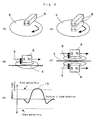
- Fig. 2 represents drawings to explain a method for applying magnetic field using permanent magnets each directed in lateral direction.
- Fig. 2 (A) shows an example where a single permanent magnet 8 having magnetic field symmetrical to the axis of the magnetic pole is arranged on upper surface of a slave medium 4 with the axis of the magnetic pole running in parallel to the surface of the slave medium 4 and the slave medium 4 is rotated.
- a magnetic field 9 is applied as shown in Fig. 2 (B) to the surface of the slave medium 4.
- Fig. 2 (C) is a diagram showing magnetic field intensity to be applied on the slave medium.
- a peak value 10 higher than the coercive force Hcs of the slave medium is present.
- Fig. 2 (D) shows an example where permanent magnets 8 each having magnetic field symmetrical to the axis of the magnetic pole are arranged on upper and lower surfaces of the slave medium 4 respectively with the axis of the magnetic pole running in parallel to the surface of the slave medium 4 and with direction of the axis of the magnetic pole of each of the magnets aligned in the same direction, and the slave medium 4 is rotated. From each of the permanent magnets 8 arranged on upper and lower surfaces of the slave medium 4 respectively, a magnetic field 9 is applied to the surface of the slave medium 4 as shown in Fig. 2 (E).
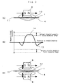
- Fig. 3 represents drawings to explain a method for transferring a pattern from the master carrier for magnetic transfer to the slave medium.
- Fig. 3 (A) is a drawing to explain application of magnetic field to a collective unit comprising the slave medium and the master carrier for magnetic transfer.
- Fig. 3 (B) is a diagram showing intensity of magnetic field given by the application of the magnetic field of Fig. 3 (A).
- a single permanent magnet 8 is arranged, which has magnetic field symmetrical to the axis of the magnetic field and capable to apply a magnetic field higher than the coercive force Hcs of the slave medium in track direction.
- a peak value 13 with lower intensity gives no influence on the transfer of the pattern from the master carrier for magnetic transfer to the slave medium. Only a peak value 14 with higher intensity contributes to the magnetic transfer.
- the peak value 14 with higher intensity can provide a good pattern regardless of the configuration of the pattern.
- Fig. 3 (C) shows a condition where permanent magnets 8 are arranged, each of which has a magnetic field symmetrical to the axis of the magnetic pole disposed on both surfaces of the collective unit 11, each of said permanent magnets being able to apply a magnetic field higher than the coercive force Hcs of the slave medium in track direction, and a magnetic field 12 is applied.
- a magnetic field reverse to the direction of the initial DC magnetization is applied to the entire surface of the collective unit 11, and a peak value with higher intensity of the magnetic field contributes to the magnetic transfer.
- a mechanism for adjusting a distance between the slave medium surface and the permanent magnet as desired By adjusting the distance between the slave medium and the permanent magnet, it is possible to obtain the magnetic field intensity as desired on the surface of the slave medium.
- a planar member with flat and smooth surface which is made of silicon, quartz plate, glass, non-magnetic metal such as aluminum or alloy, ceramics, synthetic resin, etc., and which has enough resistance to processing environment such as temperature in etching and film forming processes may be used.
- photoresist On a substrate with flat and smooth surface, photoresist is coated, and light exposure or development is performed using a photo mask to match the pattern of pre-format. Or, the photoresist is directly marked, and a pattern corresponding to the pre-format information is formed.
- etching of the substrate is performed corresponding to the pattern by etching means such as reactive etching, physical etching using argon plasma, or etching using liquid.
- the depth of the hole to be formed by the etching should be a depth corresponding to thickness of a magnetic layer formed as a transfer information recording portion. It is preferably 20 - 1000 nm. If it is too thick, spreading width of the magnetic field becomes too large, and this is not desirable.
- the holes to be formed have preferably uniform depth so that bottom surface can be formed with a surface plane which runs in parallel to the surface of the substrate.
- the hole has preferably such a shape that its cross-section in the track direction perpendicular to the surface is of rectangular shape.
- the magnetic material is processed by vacuum film forming means such as vacuum deposition method, sputtering method, ion plating method, and a film of magnetic material is formed up to the surface of the substrate in thickness to correspond to the formed hole.
- vacuum film forming means such as vacuum deposition method, sputtering method, ion plating method, and a film of magnetic material is formed up to the surface of the substrate in thickness to correspond to the formed hole.
- Magnetic characteristics of the transfer information recording portion are as follows: coercive force (Hcs) not more than 2500 Oe, or more preferably, 5 - 1500 Oe; saturation magnetic flux density (Bs) not less than 0.3 T (Tesla), or more preferably, not less than 0.5 T.
- photoresist is removed by lift-off method.
- the surface is polished, and burrs are removed if any, and the surface is flattened.
- cobalt, iron or their alloys having high magnetic flux density may be used. More concretely, Co, CoPtCr, CoCr, CoPtCrTa, CoPtCrNbTa, CoCrB, CoNi, Fe, FeCo, FePt, etc. may be used.
- the thickness of the magnetic layer is preferably 20 - 1000 nm, or more preferably, 30 - 500 nm. If it is too thick, resolution of recording is decreased.
- magnetic flux density is high and it is in the same direction as the slave medium, e.g. in intra-surface direction in case of intra-surface recording, and to have magnetic anisotropy in vertical direction in case of vertical recording.
- the magnetic material has a structure of fine magnetic particles or amorphous structure because sharp edge can be produced.
- a non-magnetic underlayer In order to provide magnetic anisotropy on the magnetic material, it is preferable to have a non-magnetic underlayer, and crystal structure and lattice constant should be the same as those of the magnetic layer. More concretely, Cr, CrTi, CoCr, CrTa, CrMo, NiAl, Ru, etc. may be used to form the film by sputtering.
- a protective film such as a diamond-like carbon film may be formed on the magnetic layer, and lubricant may be provided.
- lubricant it is more preferable that diamond-like carbon film of 5 - 30 nm and lubricant are present. The reason why lubricant must be provided is as follows: When deviation is caused during the contact process with the slave medium and this deviation is to be corrected, friction occurs, and if there is no lubricant layer, durability may be decreased.
- the master carrier for magnetic transfer according to the present invention can be used not only in the transfer of magnetic recording information to a disk-type magnetic recording medium such as hard disk, large capacity removable type magnetic recording medium, etc. but also in the transfer of magnetic recording information to a card-type magnetic recording medium or a tape-type magnetic recording medium.
- a disk-like pattern was formed by radial lines extending from the center of the disk to a position of 20 - 40 mm in radial direction with equal spacing of 10 ⁇ in width.
- the spacing of the lines was set to 10 ⁇ m at the innermost position, i.e. 20 mm in radial direction.
- Permanent magnets were arranged on both surfaces of the slave medium respectively as shown in Fig. 2 so that peak magnetic field intensity on the surface of the slave medium was to be 5000 Oe, i.e. two times as much as the coercive force Hcs of the slave medium, and initial DC magnetization of the slave medium was performed.
- the slave medium under initial DC magnetization and the master carrier for magnetic transfer were brought closely together.
- magnetic field was applied in reverse direction to the magnetization of the slave medium, and magnetic transfer was performed.
- these were squeezed with a rubber plate interposed between them, and pressure was applied on an aluminum plate.
- An electromagnetic transfer characteristics measuring system manufactured by Kyodo Electronics; SS-60 was used to evaluate transfer signal of the slave medium.
- An MR head with the following performance data was used: reproducing head gap 0.33 ⁇ m; reproduction track width 2.6 ⁇ m; recording head gap 0.4 ⁇ m; and recording track width 3.5 ⁇ m.
- Reading signal was processed by a spectro-analyzer for frequency analysis, and a difference (C/N) between peak intensity of primary signal (C) and extrapolated medium noise (N) was determined.
- C/N peak intensity of primary signal
- N extrapolated medium noise
- Hcs of slave medium 2500 Oe Peak intensity of magnetic field for transfer (Oe) Ratio to Hcs ⁇ C/N (dB) 750 0.3 * 1,250 0.5 -10.2 1,500 0.6 -4.3 2,000 0.8 -1.7 2,250 0.9 -0.3 2,500 1.0 0.0 2,750 1.1 -0.2 3,000 1.2 -1.4 3,250 1.3 -3.8 3,500 1.4 -9.6 3,750 1.5 -15.8 4,000 1.6 * 5,000 2.0 *
- Hcs of slave medium 2500 Oe Peak intensity of magnetic field for transfer (Oe) Ratio to Hcs ⁇ C/N (dB) 750 0.3 * 1,250 0.5 -10.5 1,500 0.6 -2.2 2,000 0.8 -0.1 2,250 0.9 -0.2 2,500 1.0 -0.1 2,750 1.1 0.0 3,000 1.2 -1.2 3,250 1.3 -1.9 3,500 1.4 -7.5 3,750 1.5 -10.8 4,000 1.6 * 5,000 2.0 *
- Hcs of slave medium 2500 Oe Peak intensity of magnetic field for transfer (Oe) Ratio to Hcs ⁇ C/N (dB) 750 0.3 * 1,250 0.5 * 1,500 0.6 * 2,000 0.8 * 2,250 0.9 * 2,500 1.0 * 2,750 1.1 * 3,000 1.2 * 3,250 1.3 * 3,500 1.4 * 3,750 1.5 * 4,000 1.6 * 5,000 2.0 *
- Hcs of slave medium 2000 Oe Peak intensity of magnetic field for transfer (Oe) Ratio to Hcs ⁇ C/N (dB) 600 0.3 * 1,000 0.5 -10.6 1,200 0.6 -3.2 1,600 0.8 -0.8 1,800 0.9 0.0 2,000 1.0 -0.2 2,200 1.1 -1.1 2,400 1.2 -2.3 2,600 1.3 -4.6 2,800 1.4 -9.6 3,000 1.5 -15.6 3,200 1.6 * 4,000 2.0 *
- Hcs of slave medium 2000 Oe Peak intensity of magnetic field for transfer (Oe) Ratio to Hcs ⁇ C/N (dB) 600 0.3 * 1,000 0.5 -15.2 1,200 0.6 -6.3 1,600 0.8 -5.6 1,800 0.9 -0.1 2,000 1.0 0.0 2,200 1.1 -0.2 2,400 1.2 -1.8 2,600 1.3 -2.5 2,800 1.4 -8.6 3,000 1.5 -16.3 3,200 1.6 * 4,000 2.0 *
- Hcs of slave medium 2000 Oe Peak intensity of magnetic field for transfer (Oe) Ratio to Hcs ⁇ C/N (dB) 600 0.3 * 1,000 0.5 * 1,200 0.6 * 1,600 0.8 * 1,800 0.9 * 2,000 1.0 * 2,200 1.1 * 2,400 1.2 * 2,600 1.3 * 2,800 1.4 * 3,000 1.5 * 3,200 1.6 * 4,000 2.0 *
Landscapes
- Manufacturing Of Magnetic Record Carriers (AREA)
Applications Claiming Priority (2)
| Application Number | Priority Date | Filing Date | Title |
|---|---|---|---|
| JP2000090256A JP2001014669A (ja) | 1999-04-26 | 2000-03-29 | 磁気転写方法および磁気転写装置 |
| JP2000090256 | 2000-03-29 |
Publications (2)
| Publication Number | Publication Date |
|---|---|
| EP1143425A2 true EP1143425A2 (de) | 2001-10-10 |
| EP1143425A3 EP1143425A3 (de) | 2006-09-20 |
Family
ID=18605885
Family Applications (1)
| Application Number | Title | Priority Date | Filing Date |
|---|---|---|---|
| EP00128742A Withdrawn EP1143425A3 (de) | 2000-03-29 | 2000-12-29 | Magnetische Übertragungsmethode und -gerät |
Country Status (4)
| Country | Link |
|---|---|
| EP (1) | EP1143425A3 (de) |
| KR (1) | KR20010093636A (de) |
| MY (1) | MY141465A (de) |
| SG (1) | SG92773A1 (de) |
Family Cites Families (9)
| Publication number | Priority date | Publication date | Assignee | Title |
|---|---|---|---|---|
| US3869711A (en) * | 1973-09-24 | 1975-03-04 | Ibm | Magnetic pattern recording |
| US4071869A (en) * | 1976-06-01 | 1978-01-31 | International Business Machines Corporation | Assembling flexible disk record structures |
| WO1981000165A1 (en) * | 1979-07-02 | 1981-01-22 | Tokyo Shibaura Electric Co | Magnetic transfer recording method |
| JPS57109134A (en) * | 1980-12-26 | 1982-07-07 | Toshiba Corp | Magnetic transferring and recording method |
| JPS60209915A (ja) * | 1984-04-02 | 1985-10-22 | Nec Corp | サ−ボ信号記録方法 |
| AU576947B2 (en) * | 1985-03-08 | 1988-09-08 | Sony Corporation | Combination magnetic transducer head |
| TW342495B (en) * | 1996-07-22 | 1998-10-11 | Matsushita Electric Industrial Co Ltd | Master information carrier, method of producing the same, and method for recording master information signal on magnetic recording medium |
| US5991104A (en) * | 1996-11-27 | 1999-11-23 | Seagate Technology, Inc. | Using servowriter medium for quickly written servo-patterns on magnetic media |
| JP3361740B2 (ja) * | 1998-03-23 | 2003-01-07 | 松下電器産業株式会社 | マスター情報磁気記録装置及び磁気記録媒体の製造方法 |
-
2000
- 2000-12-20 SG SG200007563A patent/SG92773A1/en unknown
- 2000-12-29 MY MYPI20006221A patent/MY141465A/en unknown
- 2000-12-29 EP EP00128742A patent/EP1143425A3/de not_active Withdrawn
-
2001
- 2001-01-10 KR KR1020010001340A patent/KR20010093636A/ko not_active Ceased
Also Published As
| Publication number | Publication date |
|---|---|
| MY141465A (en) | 2010-04-30 |
| EP1143425A3 (de) | 2006-09-20 |
| KR20010093636A (ko) | 2001-10-29 |
| SG92773A1 (en) | 2002-11-19 |
Similar Documents
| Publication | Publication Date | Title |
|---|---|---|
| US7199953B2 (en) | Magnetic transfer master medium, magnetic transfer method, and magnetic transfer master medium forming method | |
| EP1187107A2 (de) | Magnetisches Übertragungsverfahren | |
| US6804069B2 (en) | Magnetic transfer method to prevent dropout of servo signal | |
| KR20030043747A (ko) | 자기전사용 마스터 담체 및 자기전사방법 | |
| JP2001014667A (ja) | 磁気転写方法および磁気転写装置 | |
| US6650490B2 (en) | Method for magnetic transfer | |
| US6602301B1 (en) | Method and apparatus for magnetic transfer | |
| US6731440B1 (en) | Method and apparatus for magnetic transfer | |
| EP1223574A1 (de) | Urträger für magnetische Übertragung | |
| US6570724B1 (en) | Method and apparatus for magnetic transfer | |
| US6577459B1 (en) | Method and apparatus for magnetic transfer | |
| US6643079B1 (en) | Method and apparatus for magnetic transfer | |
| KR20010093638A (ko) | 자기전사방법 및 자기전사장치 | |
| EP1143423B1 (de) | Magnetische Übertragungsmethode und -gerät | |
| US7139140B2 (en) | Method and apparatus of magnetically transferring information signal from master medium to slave medium | |
| US7236317B2 (en) | Magnetic transfer method | |
| EP1143424A2 (de) | Magnetische Übertragungsmethode und -gerät | |
| EP1143425A2 (de) | Magnetische Übertragungsmethode und -gerät | |
| JP2001101657A (ja) | 磁気転写方法および磁気転写装置 | |
| JP2003141715A (ja) | 磁気転写用マスター担体 | |
| EP1168310A2 (de) | Magnetische Übertragungsmethode und -gerät | |
| JP3986951B2 (ja) | 磁気転写用マスター担体および磁気転写方法 | |
| JP2001028126A (ja) | 磁気転写方法および磁気転写装置 | |
| JP2002342923A (ja) | 磁気転写方法 | |
| JP2001014671A (ja) | 磁気転写方法および磁気転写装置 |
Legal Events
| Date | Code | Title | Description |
|---|---|---|---|
| PUAI | Public reference made under article 153(3) epc to a published international application that has entered the european phase |
Free format text: ORIGINAL CODE: 0009012 |
|
| AK | Designated contracting states |
Kind code of ref document: A2 Designated state(s): AT BE CH CY DE DK ES FI FR GB GR IE IT LI LU MC NL PT SE TR |
|
| AX | Request for extension of the european patent |
Free format text: AL;LT;LV;MK;RO;SI |
|
| PUAL | Search report despatched |
Free format text: ORIGINAL CODE: 0009013 |
|
| AK | Designated contracting states |
Kind code of ref document: A3 Designated state(s): AT BE CH CY DE DK ES FI FR GB GR IE IT LI LU MC NL PT SE TR |
|
| AX | Request for extension of the european patent |
Extension state: AL LT LV MK RO SI |
|
| RAP1 | Party data changed (applicant data changed or rights of an application transferred) |
Owner name: FUJIFILM CORPORATION |
|
| AKX | Designation fees paid | ||
| STAA | Information on the status of an ep patent application or granted ep patent |
Free format text: STATUS: THE APPLICATION IS DEEMED TO BE WITHDRAWN |
|
| 18D | Application deemed to be withdrawn |
Effective date: 20070321 |
|
| REG | Reference to a national code |
Ref country code: DE Ref legal event code: 8566 |