EP1143570A2 - Dispositif pour le montage flottant d'un connecteur à un panneau - Google Patents
Dispositif pour le montage flottant d'un connecteur à un panneau Download PDFInfo
- Publication number
- EP1143570A2 EP1143570A2 EP01108014A EP01108014A EP1143570A2 EP 1143570 A2 EP1143570 A2 EP 1143570A2 EP 01108014 A EP01108014 A EP 01108014A EP 01108014 A EP01108014 A EP 01108014A EP 1143570 A2 EP1143570 A2 EP 1143570A2
- Authority
- EP
- European Patent Office
- Prior art keywords
- latch
- connector assembly
- connector
- connecting device
- adapter
- Prior art date
- Legal status (The legal status is an assumption and is not a legal conclusion. Google has not performed a legal analysis and makes no representation as to the accuracy of the status listed.)
- Granted
Links
- 230000000295 complement effect Effects 0.000 claims description 16
- 230000013011 mating Effects 0.000 claims description 11
- 239000000758 substrate Substances 0.000 claims description 3
- 239000000835 fiber Substances 0.000 description 13
- 239000013307 optical fiber Substances 0.000 description 5
- 230000000712 assembly Effects 0.000 description 3
- 238000000429 assembly Methods 0.000 description 3
- 239000000463 material Substances 0.000 description 3
- 230000005540 biological transmission Effects 0.000 description 2
- 230000014759 maintenance of location Effects 0.000 description 2
- 230000004308 accommodation Effects 0.000 description 1
- 239000000919 ceramic Substances 0.000 description 1
- 230000009977 dual effect Effects 0.000 description 1
- 238000003780 insertion Methods 0.000 description 1
- 230000037431 insertion Effects 0.000 description 1
- 238000004519 manufacturing process Methods 0.000 description 1
- 239000002991 molded plastic Substances 0.000 description 1
- 239000004033 plastic Substances 0.000 description 1
Images



Classifications
-
- G—PHYSICS
- G02—OPTICS
- G02B—OPTICAL ELEMENTS, SYSTEMS OR APPARATUS
- G02B6/00—Light guides; Structural details of arrangements comprising light guides and other optical elements, e.g. couplings
- G02B6/24—Coupling light guides
- G02B6/36—Mechanical coupling means
-
- G—PHYSICS
- G02—OPTICS
- G02B—OPTICAL ELEMENTS, SYSTEMS OR APPARATUS
- G02B6/00—Light guides; Structural details of arrangements comprising light guides and other optical elements, e.g. couplings
- G02B6/24—Coupling light guides
- G02B6/36—Mechanical coupling means
- G02B6/38—Mechanical coupling means having fibre to fibre mating means
- G02B6/3807—Dismountable connectors, i.e. comprising plugs
- G02B6/389—Dismountable connectors, i.e. comprising plugs characterised by the method of fastening connecting plugs and sockets, e.g. screw- or nut-lock, snap-in, bayonet type
-
- G—PHYSICS
- G02—OPTICS
- G02B—OPTICAL ELEMENTS, SYSTEMS OR APPARATUS
- G02B6/00—Light guides; Structural details of arrangements comprising light guides and other optical elements, e.g. couplings
- G02B6/24—Coupling light guides
- G02B6/36—Mechanical coupling means
- G02B6/38—Mechanical coupling means having fibre to fibre mating means
- G02B6/3807—Dismountable connectors, i.e. comprising plugs
- G02B6/389—Dismountable connectors, i.e. comprising plugs characterised by the method of fastening connecting plugs and sockets, e.g. screw- or nut-lock, snap-in, bayonet type
- G02B6/3893—Push-pull type, e.g. snap-in, push-on
-
- G—PHYSICS
- G02—OPTICS
- G02B—OPTICAL ELEMENTS, SYSTEMS OR APPARATUS
- G02B6/00—Light guides; Structural details of arrangements comprising light guides and other optical elements, e.g. couplings
- G02B6/24—Coupling light guides
- G02B6/36—Mechanical coupling means
- G02B6/38—Mechanical coupling means having fibre to fibre mating means
- G02B6/3807—Dismountable connectors, i.e. comprising plugs
- G02B6/3897—Connectors fixed to housings, casing, frames or circuit boards
-
- G—PHYSICS
- G02—OPTICS
- G02B—OPTICAL ELEMENTS, SYSTEMS OR APPARATUS
- G02B6/00—Light guides; Structural details of arrangements comprising light guides and other optical elements, e.g. couplings
- G02B6/24—Coupling light guides
- G02B6/36—Mechanical coupling means
- G02B6/38—Mechanical coupling means having fibre to fibre mating means
- G02B6/3807—Dismountable connectors, i.e. comprising plugs
- G02B6/381—Dismountable connectors, i.e. comprising plugs of the ferrule type, e.g. fibre ends embedded in ferrules, connecting a pair of fibres
- G02B6/3818—Dismountable connectors, i.e. comprising plugs of the ferrule type, e.g. fibre ends embedded in ferrules, connecting a pair of fibres of a low-reflection-loss type
- G02B6/3821—Dismountable connectors, i.e. comprising plugs of the ferrule type, e.g. fibre ends embedded in ferrules, connecting a pair of fibres of a low-reflection-loss type with axial spring biasing or loading means
-
- G—PHYSICS
- G02—OPTICS
- G02B—OPTICAL ELEMENTS, SYSTEMS OR APPARATUS
- G02B6/00—Light guides; Structural details of arrangements comprising light guides and other optical elements, e.g. couplings
- G02B6/24—Coupling light guides
- G02B6/36—Mechanical coupling means
- G02B6/38—Mechanical coupling means having fibre to fibre mating means
- G02B6/3807—Dismountable connectors, i.e. comprising plugs
- G02B6/3833—Details of mounting fibres in ferrules; Assembly methods; Manufacture
- G02B6/3847—Details of mounting fibres in ferrules; Assembly methods; Manufacture with means preventing fibre end damage, e.g. recessed fibre surfaces
- G02B6/3849—Details of mounting fibres in ferrules; Assembly methods; Manufacture with means preventing fibre end damage, e.g. recessed fibre surfaces using mechanical protective elements, e.g. caps, hoods, sealing membranes
Definitions
- This invention generally relates to the art of connector assemblies and, particularly, a connector assembly for mounting through an aperture in a panel and having floating movement relative to the panel.
- a typical fiber optic connector includes a ferrule which mounts and centers an optical fiber or fibers within the connector.
- the ferrule may be fabricated of such material as ceramic.
- a ferrule holder or other housing component of the connector embraces the ferrule and may be fabricated of such material as molded plastic.
- a spring may be disposed within the housing or ferrule holder such that the ferrule is yieldably biased forwardly for engaging another fiber-mounting ferrule of a mating connecting device.
- a pair of fiber optic connectors or a connector and another optical fiber transmission device often are mated in an adapter which centers the fibers to provide low insertion losses.
- the adapter couples the connectors together so that their encapsulated fibers connect end-to-end.
- the adapter may be an in-line component, or the adapter can be designed for mounting in an aperture in a panel, backplane, circuit board or the like.
- the adapter may be mounted on a printed circuit board such as a motherboard, and one of the connectors received by the adapter may be mounted to a daughterboard.
- the chassis or panel and its mounted connector may be assembled in relation to another frame component or a printed circuit board, backplane or the like. By providing some degree of floating movement for the connector, accommodation is made for manufacturing tolerances when the entire system is assembled.
- the present invention is directed to a new and improved latch-release system wherein an adapter and a panel-mounted connector is fixed against any floating movement relative to the panel to allow easy mating of a second connector, and the panel-mounted connector is released upon mating to allow limited floating movement of the connector assembly relative to the panel.
- the concepts of the invention are not limited to this particular adapter/connector arrangement.
- An object, therefore, of the invention is to provide a new and improved connector assembly for mounting through an aperture in a panel, the aperture defining an axis, and the assembly providing for floating movement when the connector arrangement is fully mated.
- the connector assembly includes a first connecting device mountable in the aperture in the panel.
- a second connecting device is insertable axially into the first connecting device.
- One of the connecting devices includes two portions relatively movable in an axial direction, with one portion being mateable with the other of the connecting devices.
- Complementary interengaging first latch means are provided between the two portions of the one connecting device to prevent the relative axial movement therebetween.
- Complementary interengaging second latch means are provided between the other of the connecting devices and the one portion of the one connecting device when the other connecting device is mated therewith.
- Release means are provided on the other of the connecting devices for releasing the first latch means between the two portions of the one connecting device to allow the mated other connecting device to float relative to the panel.
- the complementary interengaging first latch means include at least one flexible latch arm on the one relatively movable portion of the one connecting device engageable with a latch member on the other portion.
- a pair of the flexible latch arms and respective latch member are provided on opposite sides of the connector assembly.
- a pair of the latch members are spaced axially of the other portion of the one connecting device for each flexible latch arm and between which the latch arm floats when the connecting devices are mated.
- the complementary interengaging second latch means comprise at least one flexible latch arm on the other of the connecting devices engageable with a latch member on the one relatively movable portion of the one connecting device.
- the release means and the second latch means comprise a single component. Therefore, the flexible latch arm on the other connecting device includes a portion thereof defining the release means for engaging and releasing the first latch means.
- the flexible latch arm includes a chamfered distal end for engaging and releasing the first latch means generally transversely of the axis.
- the flexible latch arm includes a latch hook spaced axially of the chamfered distal end for engaging the latch member on the one relatively movable portion of the one connecting device.
- the first connecting device is shown herein in the form of a two-part adapter mountable in the aperture in the panel.
- the second connecting device is fixed to a substrate such as a printed circuit board.
- the invention is not limited to this precise connector assembly.
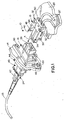
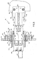
- connector assembly 10 for mounting through an aperture 12 (Fig. 3) in a panel 14.
- the panel may be a printed circuit board and, in the connector scheme shown herein, would be considered the "mother” board.
- connector assembly 10 includes a first connecting device, generally designated 16, and a second connecting device, generally designated 18.
- the first connecting device is mountable in aperture 12 in panel 14 on an axis 20 (Fig. 3) defined by the aperture.
- the second connecting device is mounted on a second printed circuit board 22 and is insertable axially into the first connecting device in the direction of arrow "A".
- Printed circuit board 22 would be considered the "daughter" board in the connector scheme herein.
- First connecting device 16 is shown herein in the form of a two-part adapter
- second connecting device 18 is shown herein in the form of a connector, particularly a fiber optic connector.
- Adapter 16 receives a pair of fiber optic connector modules, generally designated 24, inserted into the rear of the adapter for mating with connector 18 inserted into a front receptacle 26 (Fig. 1) of the adapter.
- Connector modules 24 are terminated to fiber optic cables 25 and connector 18 is terminated to fiber optic cables 27.
- fiber optic connector 18 could be an electrical connector terminated to discrete electrical wires
- connector modules 24 also could be electrical connectors terminated to electrical cables.
- adapter 16 is a two-part adapter including an outer adapter part and a relatively movable inner adapter part.
- Connector modules 14 are inserted into the inner adapter part.
- the inner adapter part equally could be a connector, itself, inside a one-piece adapter for mating with connector 18.
- fiber optic connector 18 includes a housing 30 fixed to daughter board 22 by means of a pair of fasteners, such as a pair of bolts 32.
- the housing has a forwardly projecting mating portion 34 which is insertable into receptacle 26 of adapter 16 in the direction of arrows "A".
- Fiber optic cables 27 have inner fiber cores (not visible in the drawings) which are terminated in a pair of ferrules 36 (Fig. 3) which project forwardly beyond mating portion 34.
- Housing 32 may be fabricated of plastic material, and a pair of flexible latch arms 38 project forwardly of the housing spaced laterally outwardly of mating portion 34.
- Each latch arm terminates in a chamfered distal end 40 with a latch hook 42 spaced immediately behind the chamfered distal end.
- latch arms 38 perform a dual function of latching with the inner, floating adapter part as well as releasing the first latch means between the adapter parts which prevent such floating.
- Adapter 16 includes an outer adapter part, generally designated 44, and a relatively movable inner adapter part, generally designated 46.
- the entire adapter is mounted within a mounting bracket 48 which, in turn, is mounted within aperture 12 in panel 14 as best seen in Fig. 3.
- Bracket 48 is fixed rigidly to the panel by means of a pair of fasteners, such as bolts 50.
- Adapter 16 is mounted within an aperture 52 in bracket 48 as best seen in Fig. 3.
- Outer adapter part 44 has an outwardly projecting flange 54 which abuts against a front face 56 of the adapter.
- a generally U-shaped retention clip 58 is inserted laterally into a pair of grooves 60 (Fig. 2) on the outside of outer adapter part 44.
- the retention clip bears against the backside of bracket 48 and combines with flange 54 of the outer adapter part to hold the two-part adapter 16 within aperture 52 in mounting bracket 48.
- a pair of spring-loaded doors or shutters 62 close the rear of inner adapter part 46 unless one or both of connector modules 24 are inserted into the rear of the adapter.
- One of the doors is shown open (i.e., without the respective connector module) in Figures 3-7 simply to facilitate the illustration.
- inner adapter part 46 includes a pair of flexible latch arms 64 on opposite sides thereof.
- the latch arms have latch hooks 66 for engaging behind a pair of latch members or bosses 68 on the inside of outer adapter part 44.
- the outer distal ends of the latch arms are chamfered, as at 70. Therefore, when adapter 16 is in its original unmated condition as shown in Figure 3, relative axial movement between the two adapter parts is prevented by the interengagement of latch hooks 66 on latch arms 64 with latch members 68.
- a second latch member 72 is spaced rearwardly of each latch member 68 to define the limit of floating movement provided by the connector assembly, as will be described.
- latch arms 64 on inner adapter part 46 and latch members 68 on outer adapter part 44 define the complementary interengaging "first" latch means which prevents relative axial movement between the adapter parts.
- latch hooks 42 on latch arms 38 of connector 18 form part a complementary interengaging "second" latch means which include a pair of latch shoulders 74 on inner adapter part 46. This interengagement will be described below.
- chamfered distal ends 40 of latch arms 38 of connector 18 provide a release means for releasing the first latch means of the two-part adapter.
- Mother board 14 typically is a larger fixed structural component, with adapter 16 mounted thereon (i.e., within mounting bracket 48).
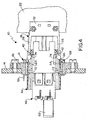
- Connector 18 and daughter board 22 are moved into mating engagement with the adapter in the direction of arrow "A" (Fig. 3) until latch hooks 42 on flexible latch arms 38 of connector 18 come into engagement with latch shoulders 74 of inner adapter part 46 as seen in Figure 4.
- distal ends 40 of latch arms 38 being chamfered, the distal ends will engage the front end of the inner adapter part to bias the latch arms outwardly until latch hooks 42 snap back inwardly into engagement with latch shoulders 74 as seen in Figure 4.
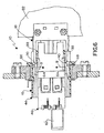
- latch arms 38 of connector 18 are effective to release the "first" latch means between the two adapter parts while the "second” latch means between connector 18 and the inner adapter part remain in engagement as seen in Figure 6.
- FIG. 7 shows that latch arms 64 of inner adapter part 46 have now snapped back outwardly in the direction of arrow "C", whereby latch hooks 66 of the latch arms now are disposed between axially spaced latch members 68 and 72 on the inside of the outer adapter part.
- the mated combination of connector 18 (and daughter board 22) and inner adapter part 46 (along with connector modules 24) now can float relative to outer adapter part 44 and panel 14 within the limits of latch hooks 66 moving in the direction of double-headed arrows "D" between latch members 68 and 72.
Landscapes
- Physics & Mathematics (AREA)
- General Physics & Mathematics (AREA)
- Optics & Photonics (AREA)
- Details Of Connecting Devices For Male And Female Coupling (AREA)
- Mechanical Coupling Of Light Guides (AREA)
Applications Claiming Priority (2)
| Application Number | Priority Date | Filing Date | Title |
|---|---|---|---|
| US09/541,207 US6315590B1 (en) | 2000-04-03 | 2000-04-03 | Floating panel mounted connector assembly |
| US541207 | 2000-04-03 |
Publications (3)
| Publication Number | Publication Date |
|---|---|
| EP1143570A2 true EP1143570A2 (fr) | 2001-10-10 |
| EP1143570A3 EP1143570A3 (fr) | 2004-05-19 |
| EP1143570B1 EP1143570B1 (fr) | 2006-06-21 |
Family
ID=24158624
Family Applications (1)
| Application Number | Title | Priority Date | Filing Date |
|---|---|---|---|
| EP01108014A Expired - Lifetime EP1143570B1 (fr) | 2000-04-03 | 2001-03-29 | Dispositif pour le montage flottant d'un connecteur à un panneau |
Country Status (7)
| Country | Link |
|---|---|
| US (1) | US6315590B1 (fr) |
| EP (1) | EP1143570B1 (fr) |
| JP (1) | JP3498216B2 (fr) |
| KR (1) | KR100400149B1 (fr) |
| CN (1) | CN1316664B (fr) |
| DE (1) | DE60120823T2 (fr) |
| TW (1) | TW579094U (fr) |
Cited By (1)
| Publication number | Priority date | Publication date | Assignee | Title |
|---|---|---|---|---|
| WO2008139218A1 (fr) * | 2007-05-15 | 2008-11-20 | Tyco Electronics Raychem Nv | Réducteur de tension pour câbles de fibre optique et cordons de raccordement |
Families Citing this family (32)
| Publication number | Priority date | Publication date | Assignee | Title |
|---|---|---|---|---|
| US6582133B2 (en) * | 2001-05-30 | 2003-06-24 | Tropic Networks Inc. | Module and method for interconnecting optoelectronic cards |
| US6702477B1 (en) | 2002-09-23 | 2004-03-09 | Fci Americas Technology, Inc. | Adapter with cap for fiber optic connector |
| JP3878902B2 (ja) * | 2002-10-21 | 2007-02-07 | 日本圧着端子製造株式会社 | 電気コネクタ |
| US20040121646A1 (en) * | 2002-12-18 | 2004-06-24 | Joseph Iamartino | Modified, field installable, field adjustable flexible angled boot for multi-conductor cables and process for installing the same |
| USD491532S1 (en) | 2003-07-30 | 2004-06-15 | Hon Hai Precision Ind. Co., Ltd. | Cable connector assembly |
| US7264401B2 (en) * | 2004-05-28 | 2007-09-04 | Corning Cable Systems Llc | Panel-mountable optical fiber splice |
| US7331717B2 (en) * | 2004-07-01 | 2008-02-19 | Amphenol Corporation | Flexible optical interconnection system |
| US7470139B2 (en) * | 2004-11-26 | 2008-12-30 | Fujitsu Component Limited | Transceiver module |
| TW200627728A (en) * | 2005-01-17 | 2006-08-01 | Sunonwealth Electr Mach Ind Co | Connector assembly structure of a terminal (1) |
| JP2007265785A (ja) * | 2006-03-28 | 2007-10-11 | Tyco Electronics Amp Kk | 電気コネクタ |
| JP4639315B2 (ja) * | 2006-09-06 | 2011-02-23 | 日本電信電話株式会社 | 光コネクタ |
| US8200126B2 (en) | 2007-11-30 | 2012-06-12 | Lexmark International, Inc. | Toner cartridges for an image forming device |
| US7972164B2 (en) * | 2009-03-24 | 2011-07-05 | Tyco Electronics Corporation | Connector assembly with a latch |
| CN102496807A (zh) * | 2011-12-09 | 2012-06-13 | 贵州航天电器股份有限公司 | 一种微型浮动安装防转机构 |
| CN104143728B (zh) * | 2013-05-09 | 2017-05-24 | 富士康(昆山)电脑接插件有限公司 | 电子设备组合 |
| US20170212313A1 (en) * | 2014-07-21 | 2017-07-27 | Te Connectivity Nederland B.V. | Fiber optic connector and fiber optic cable assembly with fiber optic cable anchored to boot of fiber optic connector |
| US9874702B2 (en) * | 2014-10-29 | 2018-01-23 | Hewlett Packard Enterprise Development Lp | Optical connector assembly apparatus |
| DE102015214377A1 (de) * | 2015-07-29 | 2017-02-02 | Brose Fahrzeugteile Gmbh & Co. Kommanditgesellschaft, Bamberg | Vorrichtung zur Befestigung und elektrischen Kontaktierung einer Fahrzeug-Fensterscheibe |
| US9482820B1 (en) | 2015-12-29 | 2016-11-01 | International Business Machines Corporation | Connecting mid-board optical modules |
| MX392117B (es) * | 2016-07-15 | 2025-03-21 | Hirschmann Automotive Gmbh | Contacto de clavija resistente a altas temperaturas para detector de detonaciones de motor de combustion interna. |
| TWI667505B (zh) * | 2016-07-27 | 2019-08-01 | 光環科技股份有限公司 | 光耦合結構及光通訊裝置 |
| TWI608261B (zh) * | 2016-11-29 | 2017-12-11 | 普泰光電股份有限公司 | 具有遮蔽件之光纖適配器 |
| TWI608262B (zh) * | 2016-11-30 | 2017-12-11 | 林雨晴 | 光纖連接器 |
| CN106842434B (zh) * | 2017-03-20 | 2018-11-13 | 中航光电科技股份有限公司 | 光纤连接器组件及光纤连接器、光纤连接器壳体组件 |
| CN107797194A (zh) * | 2017-10-17 | 2018-03-13 | 安徽电信器材贸易工业有限责任公司 | 一种固定光缆接头的装置 |
| FI3677938T3 (fi) * | 2017-12-28 | 2023-10-09 | Fujikura Ltd | Optinen liitin ja menetelmä optisen liittimen kytkemiseksi |
| CN111630423B (zh) * | 2018-01-23 | 2022-03-04 | 住友电气工业株式会社 | 光连接构造 |
| JP2019212404A (ja) * | 2018-06-01 | 2019-12-12 | 住友電装株式会社 | コネクタ |
| TWM598415U (zh) * | 2020-01-16 | 2020-07-11 | 建毅科技股份有限公司 | 光纖適配器 |
| DE202021004326U1 (de) * | 2020-07-22 | 2023-09-05 | Brose Fahrzeugteile Se & Co. Kommanditgesellschaft, Bamberg | Fensterheber eines Kraftfahrzeugs mit einer Schienengleiterbaugruppe |
| KR102804895B1 (ko) * | 2020-11-16 | 2025-05-09 | 현대자동차주식회사 | 차량의 도어글래스용 전력 공급 장치 |
| TWM629291U (zh) | 2021-07-07 | 2022-07-11 | 大陸商富加宜電子(南通)有限公司 | 一種混合式連接器 |
Family Cites Families (17)
| Publication number | Priority date | Publication date | Assignee | Title |
|---|---|---|---|---|
| US5259052A (en) * | 1984-06-08 | 1993-11-02 | Amp Incorporated | High precision optical fiber connectors |
| JPS61213811A (ja) * | 1985-03-19 | 1986-09-22 | Sumitomo Electric Ind Ltd | 光コネクタ |
| US4718857A (en) * | 1987-04-10 | 1988-01-12 | Burndy Corporation | Electrical connectors and clips and methods of use |
| JP2573753B2 (ja) * | 1991-04-01 | 1997-01-22 | 矢崎総業株式会社 | コネクタ |
| US5382177A (en) * | 1991-11-21 | 1995-01-17 | The Whitaker Corporation | Connector housing with improved latch members |
| US5325454A (en) * | 1992-11-13 | 1994-06-28 | International Business Machines, Corporation | Fiber optic connector housing |
| EP0713111A1 (fr) * | 1994-11-15 | 1996-05-22 | The Whitaker Corporation | Connecteur étanché à fibres optiques multiposition |
| JP3200546B2 (ja) * | 1995-09-04 | 2001-08-20 | 矢崎総業株式会社 | 可動コネクタ |
| US5619604A (en) * | 1996-02-26 | 1997-04-08 | Alcoa Fujikura Limited | Multi-fiber optical connector |
| EP0805366A1 (fr) * | 1996-05-02 | 1997-11-05 | Harting KGaA | Connecteur |
| US5692080A (en) * | 1996-10-03 | 1997-11-25 | Adc Telecommunications, Inc. | Double ferrule SC connector and adapter |
| JP3535952B2 (ja) | 1997-05-08 | 2004-06-07 | 古河電気工業株式会社 | バックパネルコネクタ |
| US6159030A (en) * | 1997-06-16 | 2000-12-12 | Lear Automotive Dearborn, Inc. | Self-aligning connecting system |
| US6041155A (en) * | 1997-12-10 | 2000-03-21 | Lucent Technologies Inc. | Universal dust cover |
| US6079881A (en) * | 1998-04-08 | 2000-06-27 | Molex Incorporated | Fiber optic connector receptacle assembly |
| US6105088A (en) * | 1998-07-10 | 2000-08-15 | Northrop Grumman Corporation | Backplane assembly for electronic circuit modules providing electronic reconfigurable connectivity of digital signals and manual reconfigurable connectivity power, optical and RF signals |
| US6464403B1 (en) | 1999-02-12 | 2002-10-15 | Huber & Suhner Ag | Optical connector |
-
2000
- 2000-04-03 US US09/541,207 patent/US6315590B1/en not_active Expired - Lifetime
-
2001
- 2001-03-27 JP JP2001134642A patent/JP3498216B2/ja not_active Expired - Fee Related
- 2001-03-29 DE DE60120823T patent/DE60120823T2/de not_active Expired - Fee Related
- 2001-03-29 EP EP01108014A patent/EP1143570B1/fr not_active Expired - Lifetime
- 2001-04-02 KR KR10-2001-0017273A patent/KR100400149B1/ko not_active Expired - Fee Related
- 2001-04-02 TW TW090205079U patent/TW579094U/zh not_active IP Right Cessation
- 2001-04-02 CN CN011124601A patent/CN1316664B/zh not_active Expired - Fee Related
Cited By (3)
| Publication number | Priority date | Publication date | Assignee | Title |
|---|---|---|---|---|
| WO2008139218A1 (fr) * | 2007-05-15 | 2008-11-20 | Tyco Electronics Raychem Nv | Réducteur de tension pour câbles de fibre optique et cordons de raccordement |
| US8417082B2 (en) | 2007-05-15 | 2013-04-09 | Tyco Electronics Raychem Bvba | Strain relief for optical fibre cables and patch cords |
| AU2008249756B2 (en) * | 2007-05-15 | 2013-11-21 | Tyco Electronics Raychem Bvba | Strain relief for optical fibre cables and patch cords |
Also Published As
| Publication number | Publication date |
|---|---|
| KR100400149B1 (ko) | 2003-10-01 |
| KR20010095219A (ko) | 2001-11-03 |
| JP3498216B2 (ja) | 2004-02-16 |
| CN1316664A (zh) | 2001-10-10 |
| EP1143570B1 (fr) | 2006-06-21 |
| JP2002082254A (ja) | 2002-03-22 |
| TW579094U (en) | 2004-03-01 |
| CN1316664B (zh) | 2010-06-16 |
| DE60120823D1 (de) | 2006-08-03 |
| EP1143570A3 (fr) | 2004-05-19 |
| DE60120823T2 (de) | 2006-10-12 |
| US6315590B1 (en) | 2001-11-13 |
Similar Documents
| Publication | Publication Date | Title |
|---|---|---|
| US6315590B1 (en) | Floating panel mounted connector assembly | |
| US6364536B1 (en) | Floating connector assembly | |
| US6240229B1 (en) | Connector assembly | |
| US6331079B1 (en) | Mounting system for a connector assembly to a substrate | |
| US6715931B1 (en) | Self-contained fiber optic connector module | |
| US6361218B1 (en) | Fiber optic connector module | |
| EP0997753B1 (fr) | Assemblage à connecteur fibre optique | |
| US6371657B1 (en) | Alignment system for mating connectors | |
| US6406192B1 (en) | Connector assembly floating mount | |
| US20050163429A1 (en) | Fiber optic connector module having rear extender | |
| EP1556721B1 (fr) | Module connecteur à fibre optique | |
| US6505976B1 (en) | Alignment pin assembly for fiber optic connectors | |
| EP1045486B1 (fr) | Assemblage d'un connecteur monté sur panneau |
Legal Events
| Date | Code | Title | Description |
|---|---|---|---|
| PUAI | Public reference made under article 153(3) epc to a published international application that has entered the european phase |
Free format text: ORIGINAL CODE: 0009012 |
|
| AK | Designated contracting states |
Kind code of ref document: A2 Designated state(s): AT BE CH CY DE DK ES FI FR GB GR IE IT LI LU MC NL PT SE TR |
|
| AX | Request for extension of the european patent |
Free format text: AL;LT;LV;MK;RO;SI |
|
| PUAL | Search report despatched |
Free format text: ORIGINAL CODE: 0009013 |
|
| AK | Designated contracting states |
Kind code of ref document: A3 Designated state(s): AT BE CH CY DE DK ES FI FR GB GR IE IT LI LU MC NL PT SE TR |
|
| AX | Request for extension of the european patent |
Extension state: AL LT LV MK RO SI |
|
| RIC1 | Information provided on ipc code assigned before grant |
Ipc: 7G 02B 6/38 A |
|
| 17P | Request for examination filed |
Effective date: 20041110 |
|
| AKX | Designation fees paid |
Designated state(s): DE FR GB IT |
|
| 17Q | First examination report despatched |
Effective date: 20050202 |
|
| GRAP | Despatch of communication of intention to grant a patent |
Free format text: ORIGINAL CODE: EPIDOSNIGR1 |
|
| GRAS | Grant fee paid |
Free format text: ORIGINAL CODE: EPIDOSNIGR3 |
|
| GRAA | (expected) grant |
Free format text: ORIGINAL CODE: 0009210 |
|
| AK | Designated contracting states |
Kind code of ref document: B1 Designated state(s): DE FR GB IT |
|
| PG25 | Lapsed in a contracting state [announced via postgrant information from national office to epo] |
Ref country code: IT Free format text: LAPSE BECAUSE OF FAILURE TO SUBMIT A TRANSLATION OF THE DESCRIPTION OR TO PAY THE FEE WITHIN THE PRESCRIBED TIME-LIMIT;WARNING: LAPSES OF ITALIAN PATENTS WITH EFFECTIVE DATE BEFORE 2007 MAY HAVE OCCURRED AT ANY TIME BEFORE 2007. THE CORRECT EFFECTIVE DATE MAY BE DIFFERENT FROM THE ONE RECORDED. Effective date: 20060621 |
|
| REG | Reference to a national code |
Ref country code: GB Ref legal event code: FG4D |
|
| REF | Corresponds to: |
Ref document number: 60120823 Country of ref document: DE Date of ref document: 20060803 Kind code of ref document: P |
|
| ET | Fr: translation filed | ||
| PLBE | No opposition filed within time limit |
Free format text: ORIGINAL CODE: 0009261 |
|
| STAA | Information on the status of an ep patent application or granted ep patent |
Free format text: STATUS: NO OPPOSITION FILED WITHIN TIME LIMIT |
|
| 26N | No opposition filed |
Effective date: 20070322 |
|
| PGFP | Annual fee paid to national office [announced via postgrant information from national office to epo] |
Ref country code: GB Payment date: 20080327 Year of fee payment: 8 Ref country code: IT Payment date: 20080326 Year of fee payment: 8 |
|
| PGFP | Annual fee paid to national office [announced via postgrant information from national office to epo] |
Ref country code: DE Payment date: 20080430 Year of fee payment: 8 Ref country code: FR Payment date: 20080317 Year of fee payment: 8 |
|
| GBPC | Gb: european patent ceased through non-payment of renewal fee |
Effective date: 20090329 |
|
| REG | Reference to a national code |
Ref country code: FR Ref legal event code: ST Effective date: 20091130 |
|
| PG25 | Lapsed in a contracting state [announced via postgrant information from national office to epo] |
Ref country code: DE Free format text: LAPSE BECAUSE OF NON-PAYMENT OF DUE FEES Effective date: 20091001 |
|
| PG25 | Lapsed in a contracting state [announced via postgrant information from national office to epo] |
Ref country code: FR Free format text: LAPSE BECAUSE OF NON-PAYMENT OF DUE FEES Effective date: 20091123 Ref country code: GB Free format text: LAPSE BECAUSE OF NON-PAYMENT OF DUE FEES Effective date: 20090329 |
|
| PG25 | Lapsed in a contracting state [announced via postgrant information from national office to epo] |
Ref country code: IT Free format text: LAPSE BECAUSE OF NON-PAYMENT OF DUE FEES Effective date: 20090329 |