EP1143748A2 - Signallisierungsdurchgangssystem - Google Patents
Signallisierungsdurchgangssystem Download PDFInfo
- Publication number
- EP1143748A2 EP1143748A2 EP01250120A EP01250120A EP1143748A2 EP 1143748 A2 EP1143748 A2 EP 1143748A2 EP 01250120 A EP01250120 A EP 01250120A EP 01250120 A EP01250120 A EP 01250120A EP 1143748 A2 EP1143748 A2 EP 1143748A2
- Authority
- EP
- European Patent Office
- Prior art keywords
- gateway
- switching network
- address
- signaling information
- packet switching
- Prior art date
- Legal status (The legal status is an assumption and is not a legal conclusion. Google has not performed a legal analysis and makes no representation as to the accuracy of the status listed.)
- Withdrawn
Links
- 230000011664 signaling Effects 0.000 title claims abstract description 101
- 230000005540 biological transmission Effects 0.000 claims abstract description 25
- 238000000034 method Methods 0.000 claims abstract description 20
- 238000013507 mapping Methods 0.000 claims description 7
- 108091006146 Channels Proteins 0.000 claims 6
- 238000006243 chemical reaction Methods 0.000 description 2
- 230000006978 adaptation Effects 0.000 description 1
- 238000010276 construction Methods 0.000 description 1
- 238000004806 packaging method and process Methods 0.000 description 1
- 230000002093 peripheral effect Effects 0.000 description 1
Images



Classifications
-
- H—ELECTRICITY
- H04—ELECTRIC COMMUNICATION TECHNIQUE
- H04Q—SELECTING
- H04Q3/00—Selecting arrangements
- H04Q3/0016—Arrangements providing connection between exchanges
- H04Q3/0025—Provisions for signalling
Definitions
- the invention relates to a method and a gateway for transparent transmission of out-of-band signaling information a circuit switching network via a packet switching network.
- the invention relates to that Transparent transmission of SS7 signaling information over an IP network.
- the SS7 signaling system is for the exchange and transmission of signaling information between exchanges / switches responsible, which in particular the assembly and disassembly of 64 kbit / s User channel connections and the control of ISDN services and additional service features.
- the SS7 signaling system is characterized in that the signaling information separated from the 64 kbit / s user channels (Base channels) on a separate signaling channel are transmitted (out-of-band signaling).
- the SS7 signaling information has a message transfer part (MTP) and separate user parts in particular for telephony (TUP) and for controlling ISDN service features (ISUP).
- MTP message transfer part
- TUP telephony
- ISUP ISDN service features
- a level 2 of the message transfer part MTP ensures against transmission errors secure transmission of the signaling channel, a Level 3 for those required for routing Functions of the signaling network.
- Level 3 contains control information in particular the address of the sending switching center (origination Point Code OPC) and the address of the receiving exchange (Destination Point Code DPC). Because signaling information to numerous useful channel connections belonging to a signaling channel must belong each signaling message to a specific one User channel are clearly identified. this happens via a CIC (Circuit Identification Code) message part.
- the CIC or user channel identifier is also a component level 3 of the message transfer part MTP.
- IP internet protocol
- a packet switching network For the transmission of information via packet switching networks the internet protocol (IP) is known.
- IP internet protocol
- a packet switching network are data for transfer into data packets packed.
- Each packet contains a header (header), in which u.a. the sender address and the recipient address are specified.
- the data packet also contains in a data part a subset of the data that is sent should be.
- IP data packets are usually sent over the Protocols transfer TCP or UDP, each over the IP layer.
- Packet switched networks are connectionless, i.e. each Package comes individually and not related to others transfer. They are therefore cheaper than circuit-switched ones Networks where connections with the full Bandwidth of a channel between two points continuously to provide. With increasing measure therefore packet switching networks are also used for transmission of information traditionally used exclusively have been transmitted in circuit switching networks. It In this context, the well-known VoIP (Voice over IP) applications, especially Internet telephony referred.
- VoIP Voice over IP
- the data to be transferred will be saved Entry into the packet switching network by means of suitable Server, hereinafter referred to as gateways, compressed and arranged in packages. This is done, for example according to ITU-T recommendation H.323. After leaving the Packet switching network, the data packets are depacketized to their destination via standard POTS / ISDN lines transfer.
- the present invention is based on the object Method and gateway for transmitting out-of-band signaling information to provide the it enable the signaling information in a simple manner to transmit transparently over a packet switching network.
- the possibility is to be created SS7 signaling information transparently over one Transfer IP packet switching network.
- the method according to the invention is then distinguished by transparent transmission of signaling information over a packet switching network characterized in that in one first gateway between the circuit and packet switching network the address of the receiving switch (Destination Point Code DPC) the address of a gateway using an assignment function is assigned to which the signaling data in Packet switching network are sent.
- This second gateway is preferably in geographical proximity, i.e. in particular in the same subnet or local exchange as the switch to which the signaling information is transmitted should be.
- the signaling information of the telecommunications network are packaged in the gateway and in the data parts of the Transfer packets to the assigned gateway. To do this the one previously assigned to the address of the switch received Address of the gateway as the destination address in the data to be transmitted Packages written. After transmission of the signaling information these are depackaged to the second gateway and put it back together.
- the address of the received switch (DPC) and the signaling information then in a manner known per se about the Transfer switching network to the received switch.
- the solution according to the invention enables the signaling information from the point of view of the circuit switching network to transmit transparently over a packet switching network. This enables the internationally standardized to be maintained SS7 signaling also in a packet switched Transport network.
- the solution according to the invention draws in addition to a high degree of transparency and compatibility also characterized in that it is a simple and therefore provides quick solution insofar as on additional protocols for the transmission of the signaling information waived over the packet switching network becomes.
- a mapping between the address of the receiving switch and the address of the gateway in the packet switching network The packages are sent to, preferably after the criterion whether the assigned gateway is geographical Proximity to the receiving switch. Under geographical Closeness is understood in particular that the Gateway in the same subnet or local exchange as the receiving switch is located. This ensures that the signaling information is only about a small distance over the circuit switching network must be transferred.
- the mapping between the address of the receiving switch and the address of a gateway in the packet switching network takes place via an assignment table. This can, for example be included directly in the first gateway or alternatively from a management system to one or more managed and updated on separate servers which the first gateway then uses. It is important that there is a clear assignment between the two addresses considered. Based on these Assignment takes place a transmission of signaling information to a specific gateway of the packet switching network and from there to the target switch (receiving Switch).
- the signaling information for several useful channel connections on the transmission link via the packet switching network multiplexed i.e. signaling information in each case to several user channel connections in one data packet written.
- the prerequisite for this is, of course, that the signaling information is the same destination address (DPC). This is the case with two gateways connect about two larger cities via an IP backbone, however often be the case.
- the gateway according to the invention which is a transparent transmission out-of-band signaling information about a Packet switching network provides a first Interface to the circuit switching network and a second interface to the packet switching network on, each in a packaging or depacketization and an adaptation of the respective data transmission standards he follows.
- allocation means provided that the address of a receiving switch (DPC) assign the address of a gateway in the packet switching network, to which the signaling information is sent. The address of the determined by the assignment Gateway as the destination address of the in the packet switching network sent packages.
- DPC receiving switch
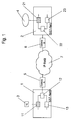
- Fig. 1 shows a telecommunications structure with two circuit switched Telecommunications networks 1, 2 on which Signaling information according to the ITU-T signaling system No. 7 will be transferred.
- the telecommunication networks 1, 2 are also referred to below as SS7 networks.
- the SS7 network 1, 2 has a large number of switches (Exchanges) 11, 12, 13, 21, 22, 23 on, between which transmit the SS7 signaling information become.
- To the switches / exchanges of the SS7 network are terminal equipment 3 or directly or via PBXs / routers local networks 4 connected.
- the two SS7 networks 1, 2 and two different networks or subnets can also be the same network that only is bridged over an IP route.
- the SS7 networks 1, 2 are each connected via a gateway 5, 6 a packet switching network 7 connected.
- a packet switching network 7 is preferably an IP backbone of a proprietary network or the internet.
- the data as connectionless IP packets transfer.
- Each gateway 5, 6 provides an interface between the SS7 network 1, 2 and the IP network 7. It is part of the SS7 network (TDM network) via one or more 2 Mbit / s lines (E1 groups) connected on which thirty-one 64 kbit / s Useful channels and a signaling channel are multiplexed.
- the data of the individual 64 kbit / s user channels in packets segmented and via the IP transport network to the gateway 6 transfer. This is well known in the art.
- the present invention relates to the transmission of associated signaling information about the IP network 7.
- IP network 7 For this purpose, consider the example of SS7 signaling information from switch 11 as the sending Switch via SS7 network 1, gateway 5, IP network 7, the gateway 6, the SS7 network 2 to the switch 21 as the receiving one Switch will be sent.
- switch 11 For this purpose, consider the example of SS7 signaling information from switch 11 as the sending Switch via SS7 network 1, gateway 5, IP network 7, the gateway 6, the SS7 network 2 to the switch 21 as the receiving one Switch will be sent.
- the gateway 5 shows the structure of a gateway 5 according to the invention.
- the gateway 5 has a first interface to the SS7 network 1 51, in which data sent to the SS7 network is packaged and any necessary protocol conversion is carried out.
- the gateway 5 is controlled by a control device 53 which from a standard microprocessor or more specialized Hardware (such as ASIC- (Application Specific Integrated -Circuit) or PLD- (Programmable Logic Device) blocks) with peripheral components and suitable control software consists.
- the control device 53 is with a Module 54 coupled, which is a mapping table to be explained having.
- Signaling information is provided by switch 11 first transmitted to the gateway 5 via the SS7 network 1 (Step 601).
- the signaling information contains in particular MTP message parts of levels 2 and 3 and the ISUP user parts for the control of ISDN service features. Alternatively, only message parts are level 3 and ISUP and / or other user parts such as TCAP (Transaction Capability Application Part) or MAP (Mobile Application Part) included.
- Level 3 contains tax information both the address of the sending switch 11 and the Address of the receiving switch 21.
- the signaling information from the control device 53 and the destination point Code DPC determined (step 602).
- the control device 53 must now determine to which address in the packet switching network the signaling information is sent should. To do this, it accesses one stored in module 54 Mapping table back, in the addresses of certain switches Assigned addresses of certain gateways in the IP network are. The assignment is preferably made such that the Signaling information is sent to a gateway, which is in the same subnet or local exchange network as the switch 21 to which the information is transmitted should.
- the corresponding assignment table can alternatively to the Filed in module 54 also from a central management system managed and updated where the Control device 53 requests a current assignment.
- the assignment table 54 in the gateway 5 is preferred arranged directly to exclude delay times. It is of course provided that the assignment data be updated regularly.
- the control device 53 assigns the destination point code DPC of the switch 21 based on the assignment table in the module 54 a specific IP address that is clearly a gateway identified in the IP network to which the signaling information be sent. In the embodiment of the 1, this is just gateway 6 (step 603).
- the signaling information to be transmitted to the switch 21 are now packaged in such a way that the signaling information written in the data parts of the IP packets (step 604).
- the signaling data will directly, i.e. without additional coding MTP level 2 written in the data part of the IP packet.
- the address of the determined is used as the destination address of the IP packet Gateway 6 set.
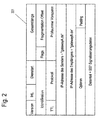
- Fig. 2 is the header of a usual Represents IP packet.
- Fig. 2 is the header of a usual Represents IP packet.
- Fig. 2 is the header of a usual Represents IP packet.
- the IP address of the recipient set according to the invention is in the Example of Fig. 2 "gatewayB.de".
- the other fields are described in a manner known per se.
- the IP packets are now sent from the gateway 5 via the IP network 7 transmitted to the gateway 6 (step 605).
- the transfer preferably takes place according to the UDP protocol.
- Fig. 3 shows a corresponding data packet that the IP header 301, the UDP header 302 and a data part 303 with the signaling information, especially the destination address DPC, the Originating address OPC, the useful channel identifier CIC and the other message parts of the message transfer part MTP levels 2 and 3 and the ISUP user part.
- the data packets are recorded in the gateway 6 and in themselves depacket in a known manner (step 606).
- the gateway 6 is constructed like the gateway 5.
- the controller of the gateway 6 reads the Destination Point Code DPC from the data part. This is preferably at least at the beginning of the data part an IP packet arranged.
- Step 607 After composing the signaling information these are then transmitted to the switch 21 via the SS7 network 2 (Step 607).
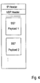
- FIG. 4 Another alternative exemplary embodiment is shown in FIG. 4 shown.
- the SS7 signaling information for several user channels in the Gateway 5 multiplexed, i.e. the signaling information several useful channel connections in the respective IP packets written.
- the signaling information on the same Switch 21 should be sent.
- the advantage of multiplexing of the signaling information is that the IP packets filled with bits faster and thus can be sent faster to the gateway 6, so that the transmission delay times are reduced become.
- the signaling information with the user data the associated or other useful channel connections multiplexed. This also enables those to be transmitted Fill up data packets faster. Then it's in a protocol to specify exactly what data signaling information and which data represent useful data.
- the mapping between the useful channel identifier CIC and the port number of the Gateways 6 is carried out in an analogous manner to the assignment of Addresses of the receiving switch 21 and the receiving gateway 6 in an assignment table, which is also in the gateway 6 is stored and accessed by the control device 53.
- the assigned port number is in the corresponding Field of the UDP header used for the transmission written.
- the advantage of the assignment between the user channel identifier CIC and The port number of the gateway received is that the Assignment of the signaling information to the user channel connections recorded faster and in further mediation of the useful channel connections is taken into account more easily can be. This makes it easier to identify the useful channel Way in the gateway 6 immediately the UDP header of the transmitted Packages are removed.
- the invention is not limited in its execution the aforementioned embodiments.
- the packages instead of following the internet protocol other packet-switched protocols such as ATM, Frame Relay or IPX. It is essential for the invention alone that for the transparent transmission of signaling information over a packet switching network of Destination address of a receiving switch a specific address is assigned to a gateway and the signaling information transmitted in packet form to this gateway become.
Landscapes
- Engineering & Computer Science (AREA)
- Computer Networks & Wireless Communication (AREA)
- Data Exchanges In Wide-Area Networks (AREA)
Abstract
Description
- Fig. 1 -
- schematisch den Aufbau eines Telekommunikationsnetzes zur Durchführung des erfindungsgemäßen Verfahrens;
- Fig. 2 -
- den Aufbau eines erfindungsgemäß ausgebildeten IP-Headers;
- Fig. 3 -
- den Aufbau eines UDP/IP Datenpaketes;
- Fig. 4 -
- einen alternativen Aufbau eines UDP/IP Datenpaketes;
- Fig. 5 -
- den Aufbau eines erfindungsgemäßen Gateways und
- Fig. 6 -
- den zeitlichen Ablauf eines Verfahrens zum transparenten Übertragen von SS7-Signalisierungsinformationen über ein Paketvermittlungsnetz.
Claims (18)
- Verfahren zum transparenten Übertragen von Außenband-Signalisierungsinformationen eines Leitungsvermittlungsnetzes über ein Paketvermittlungsnetz, bei dem die Signalisierungsinformationen von einem sendenden Switch (11) zu einem ersten Gateway (5), der Leitungs- und Paketvermittlungsnetz koppelt, vom ersten Gateway über das Paketvermittlungsnetz (7) zu einem zweiten Gateway (6) und vom zweiten Gateway (6) zu einem empfangenden Switch (21) übertragen werden, wobeia) die Signalisierungsinformationen jeweils die Adresse (OPC) des sendenden Switch (11) und die Adresse (DPC) des empfangenden Switch (21) im Leitungsvermittlungsnetz enthalten,b) im ersten Gateway (5) die Adresse (DPC) des empfangenden Switch (21) erfaßt und dieser anhand einer Zuordnungstabelle die Adresse eines Gateway (6) zugeordnet wird, der als zweiter Gateway dient,c) die Signalisierungsinformationen im ersten Gateway (5) paketiert und als Pakete bestehend aus Header (301, 302) und Datenteil (303) über das Paketvermittlungsnetz an den zweiten Gateway (6) übertragen werden, wobeid) die Header (301) der Pakete als Zieladresse die zugeordnete Adresse des zweiten Gateway (6) und die Datenteile (303) der Datenpakete die zu übertragenden Signalisierungsinformationen aufweisen,e) im zweiten Gateway (6) die Signalisierungsinformationen depaketiert und über das Leitungsvermittlungsnetz an den empfangenden Switch (21) übertragen werden.
- Verfahren nach Anspruch 1, bei dem die Adresse des zweiten Gateway der Adresse des empfangenden Switch (DPC) nach dem Kriterium zugeordnet wird, ob der zweite Gateway sich in geographischer Nähe zum empfangenden Switch, insbesondere in dem gleichen Teilnetz oder Ortsvermittlungsnetz wie der empfangende Switch befindet.
- Verfahren nach Anspruch 1, bei dem die Zuordnungstabelle, anhand derer die Adresse des empfangenden Switch (DPC) der Adresse eines Gateway im Paketvermittlungsnetz zugeordnet wird, im ersten Gateway vorhanden ist oder von einem Server eines Managementsystems verwaltet wird.
- Verfahren nach Anspruch 1, bei dem die Signalisierungsinformationen im ersten Gateway direkt und ohne weitere Kodierung in die Datenteile der zu übertragenden Pakete geschrieben werden.
- Verfahren nach mindestens einem der Ansprüche 1 bis 4, bei dem das Leitungsvermittlungsnetz ein Telekommunikationsnetz mit Zentralkanalsignalisierung gemäß dem ITU-T-Signalisierungssystem Nr. 7 ist und die zu übertragenden Signalisierungsinformationen solche des ITU-T-Signalisierungssystem Nr. 7, insbesondere Anwenderinformationen sind.
- Verfahren nach mindestens einem der Ansprüche 1 bis 5, bei dem die Pakete im Paketvermittlungsnetz entsprechend dem Internet-Protokoll (IP) oder anderen paketvermittelten Protokollen wie ATM, Frame Relay oder IPX gebildet sind.
- Verfahren nach den Ansprüchen 4, 5 und 6, bei dem neben Anwenderinformationen auch MTP-Nachrichten insbesondere der Ebenen 2 und 3 in die Datenteile der Pakete geschrieben werden.
- Verfahren nach den Ansprüchen 5 und 6, bei dem die Adresse des empfangenden Switch (DPC) an den Anfang des Datenteils mindestens eines Pakets geschrieben und im empfangenden Gateway aus dem Datenteil ausgelesen wird.
- Verfahren nach mindestens einem der Ansprüche 5 bis 8, bei dem die IP-Pakete im Paketvermittlungsnetz gemäß den Protokollen UDP oder TCP übertragen werden und Signalisierungsinformation (CIC) betreffend die Zuordnung der Signalisierung zu einem bestimmten Nutzkanal einer bestimmten Portnummer des TCP/UDP Headers zugeordnet werden.
- Verfahren nach mindestens einem der Ansprüche 5 bis 9, bei dem die Pakete neben zu übertragenden Signalisierungsinformationen zusätzlich Nutzdaten der zugehörigen Nutzkanalverbindungen enthalten.
- Verfahren nach mindestens einem der Ansprüche 5 bis 10, bei dem die Signalisierungsinformationen zu mehreren Nutzkanalverbindungen auf der Übertragungsstrecke über das Paketvermittlungsnetz gemultiplext werden.
- Gateway zwischen einem Leitungsvermittlungsnetz und einem Paketvermittlungsnetz, der Außenband-Signalisierungsinformationen des Leitungsvermittlungsnetzes zwischen den beiden Netzen transparent überträgt, mita) einer ersten Schnittstelle (51) gegenüber dem Leitungsvermittlungsnetz (1),b) einer zweiten Schnittstelle (52) gegenüber dem Paketvermittlungsnetz (7),c) Zuordnungsmitteln (53, 54), die der Adresse eines empfangenden Switch (21) die Adresse eines Gateway (6) zuordnen, an den die Signalisierungsinformationen über das Paketvermittlungsnetz (7) gesandt werden,d) Mitteln (53) zum Setzen der Adresse des durch die Zuordnungsmittel ermittelten Gateway als Zieladresse der an den Gateway (6) gesendeten Pakete.
- Gateway nach Anspruch 12, bei dem die Zuordnungsmittel (53, 54) auf eine Zuordnungstabelle zurückgreifen, in der die Adressen von Switches des Leitungsvermittlungsnetzes den Adressen von Gateways des Paketvermittlungsnetzes zugeordnet sind.
- Gateway nach Anspruch 13, bei dem die Zuordnungstabelle eine Zuordnung nach dem Kriterium vornimmt, ob der zugeordnete Gateway (6) sich in geographischer Nähe zum empfangenden Switch (21), insbesondere in dem gleichen Teilnetz oder Ortsvermittlungsnetz wie der empfangende Switch befindet.
- Gateway nach mindestens einem der Ansprüche 12 bis 14, der zusätzlich Mittel aufweist, die die Adresse des empfangenden Switch (21) an den Anfang des Datenteils (303) mindestens eines Pakets schreiben.
- Gateway nach mindestens einem der Ansprüche 12 bis 15, der zusätzlich Mittel aufweist, die die Adresse (DPC) des empfangenden Switch (21) in ein unbenutzes oder nicht unbedingt benötigtes Feld des Headers (301) mindestens eines Pakets schreiben.
- Gateway nach mindestens einem der Ansprüche 12 bis 16, der zusätzlich Mittel aufweist, die Signalisierungsinformationen (CIC) betreffend die Zuordnung der Signalisierung zu einem bestimmten Nutzkanal einer bestimmten Portnummer eines TCP/UDP Headers zuordnen und die Portnummer entsprechend setzen.
- Gateway nach mindestens einem der Ansprüche 12 bis 17, der zusätzlich einen Multiplexer aufweist, der die Signalisierungsinformationen mehrerer Nutzkanalverbindungen in die über das Paketvermittlungnetz an eine bestimmte Adresse zu übertragenden Pakete schreibt.
Applications Claiming Priority (2)
| Application Number | Priority Date | Filing Date | Title |
|---|---|---|---|
| DE2000117631 DE10017631A1 (de) | 2000-04-05 | 2000-04-05 | Verfahren und Gateway zum transparenten Übertragen von Außenband-Signalisierungsinformationen über ein Paketvermittlungsnetz |
| DE10017631 | 2000-04-05 |
Publications (2)
| Publication Number | Publication Date |
|---|---|
| EP1143748A2 true EP1143748A2 (de) | 2001-10-10 |
| EP1143748A3 EP1143748A3 (de) | 2004-03-24 |
Family
ID=7638129
Family Applications (1)
| Application Number | Title | Priority Date | Filing Date |
|---|---|---|---|
| EP01250120A Withdrawn EP1143748A3 (de) | 2000-04-05 | 2001-04-05 | Signallisierungsdurchgangssystem |
Country Status (2)
| Country | Link |
|---|---|
| EP (1) | EP1143748A3 (de) |
| DE (1) | DE10017631A1 (de) |
Cited By (2)
| Publication number | Priority date | Publication date | Assignee | Title |
|---|---|---|---|---|
| CN116112316A (zh) * | 2023-01-06 | 2023-05-12 | 深圳感臻智能股份有限公司 | 一种设备通信方法及装置 |
| US12549508B2 (en) | 2023-02-10 | 2026-02-10 | T-Mobile Usa, Inc. | Increase capacity of a wireless telecommunication network |
Families Citing this family (1)
| Publication number | Priority date | Publication date | Assignee | Title |
|---|---|---|---|---|
| DE10200165A1 (de) | 2002-01-04 | 2003-07-10 | Klaus Rock | Verfahren zur Reduzierung der Latenzzeit bei der interaktiven Datenkommunikation über ein Satellitennetzwerk |
Family Cites Families (3)
| Publication number | Priority date | Publication date | Assignee | Title |
|---|---|---|---|---|
| CA2193015C (en) * | 1996-01-04 | 2001-04-03 | Dominic Ricciardi | Network architecture for routing of adjunct based services |
| US5974052A (en) * | 1996-05-10 | 1999-10-26 | U.S.T.N. Services | Frame relay access device and method for transporting SS7 information between signaling points |
| US5923659A (en) * | 1996-09-20 | 1999-07-13 | Bell Atlantic Network Services, Inc. | Telecommunications network |
-
2000
- 2000-04-05 DE DE2000117631 patent/DE10017631A1/de not_active Ceased
-
2001
- 2001-04-05 EP EP01250120A patent/EP1143748A3/de not_active Withdrawn
Cited By (2)
| Publication number | Priority date | Publication date | Assignee | Title |
|---|---|---|---|---|
| CN116112316A (zh) * | 2023-01-06 | 2023-05-12 | 深圳感臻智能股份有限公司 | 一种设备通信方法及装置 |
| US12549508B2 (en) | 2023-02-10 | 2026-02-10 | T-Mobile Usa, Inc. | Increase capacity of a wireless telecommunication network |
Also Published As
| Publication number | Publication date |
|---|---|
| DE10017631A1 (de) | 2001-10-18 |
| EP1143748A3 (de) | 2004-03-24 |
Similar Documents
| Publication | Publication Date | Title |
|---|---|---|
| EP0929884B1 (de) | Verfahren zur übertragung von daten in einem telekommunikationsnetz und switch zur durchführung des verfahrens | |
| DE10158822B4 (de) | Verfahren zum Bereitstellen von Leistungsmerkmalen für Alternativ-Verbindungen von Primär-Verbindungen | |
| DE60037368T2 (de) | Verfahren und Architektur zur Unterstüzung von mehreren Diensten in einem Etikettvermittlungsnetzwerk | |
| DE60208035T2 (de) | Signalübergapepunkt, verfahren und system mit internetprotokollfähigkeit in einem telekommunikationsnetzwerk | |
| DE69905807T2 (de) | Optimale Lenkung von Anrufen über das öffentliche Telefonnetz und über Internet | |
| DE69636242T2 (de) | Verfahren und vorrichtung zur mehrfachzellenübertragung | |
| EP1397009A1 (de) | Verfahren und Vorrichtung zur Nachrichtenlenkung in SS7-Netzen | |
| DE60030273T2 (de) | Verfahren und systeme zur lenkung von zeichengabenachrichten in einem kommunikationsnetz unter verwendung von sprechkreisadress (cic)-information | |
| DE60029105T2 (de) | Ip - basiertes fernsprechsystem | |
| EP1143748A2 (de) | Signallisierungsdurchgangssystem | |
| DE60314255T2 (de) | Signalisierung einer trägerverbindung in einer verteilten architektur | |
| DE69823171T2 (de) | Knoten zur unterstützung von verbindungen zur übertragung von nachrichten länger als der aktuellen mtp schicht 2 entsprechend | |
| DE10144356B4 (de) | Verfahren zur Leitweglenkung von Datenpaketen | |
| EP0580012A1 (de) | Verfahren zum Übertragen von Signalisierungssignalen und Nachrichtensignalen zwischen ISDN-Endgeräten unterschiedlicher ISDN-Netze unter Einbeziehung eines ATM-Netzes | |
| DE102004049465B4 (de) | Gleichmäßige Verteilung von SS7-Verkehr auf mehrere Verbindungen | |
| EP1701557B1 (de) | Verfahren zum Vermitteln von SS7-Nachrichten, Netzwerkanordnung sowie Netzwerkelement | |
| DE60022359T2 (de) | Verfahren und Mediensteuerung zum Senden von Signalisierungsnachrichten über ein Kommunikationssystem bestehend aus zwei unterschiedlichen Transportnetzen | |
| WO2000011883A1 (de) | Signalisierungssystem eines signalisierungspunktes | |
| DE102005041617B3 (de) | Verfahren zur verbesserten Nutzung eines Schnittstellensystems mit Adresskomponenten | |
| EP1521497A2 (de) | Universal-Vermittlungsstelle, Verfahren zum Durchführen einer Vermittlungsaufgabe, Eingangseinheit, Ausgangseinheit und Anschlusseinheit | |
| EP1521496A1 (de) | Universal-Vermittlungsstelle, Verfahren zum Durchführen einer Vermittlungsaufgabe, Eingangseinheit, Ausgangseinheit und Anschlusseinheit | |
| EP1119950A2 (de) | Verfahren zum verbindungsaufbau für ein kommunikationsnetz | |
| CH693196A5 (de) | Verfahren für die Anbindung des Signalisiernetzes eines leitungsvermittelnden Netzes an ein paketvermittelndes, insbesondere auf dem Internet-Protokoll basierendes Netz. | |
| DE19930116A1 (de) | Vermittlungsverfahren | |
| WO2000042781A1 (de) | Verfahren zur realisierung von mehrfach-punktcodes in einer vermittlungsstelle |
Legal Events
| Date | Code | Title | Description |
|---|---|---|---|
| PUAI | Public reference made under article 153(3) epc to a published international application that has entered the european phase |
Free format text: ORIGINAL CODE: 0009012 |
|
| AK | Designated contracting states |
Kind code of ref document: A2 Designated state(s): AT BE CH CY DE DK ES FI FR GB GR IE IT LI LU MC NL PT SE TR |
|
| AX | Request for extension of the european patent |
Free format text: AL;LT;LV;MK;RO;SI |
|
| PUAL | Search report despatched |
Free format text: ORIGINAL CODE: 0009013 |
|
| AK | Designated contracting states |
Kind code of ref document: A3 Designated state(s): AT BE CH CY DE DK ES FI FR GB GR IE IT LI LU MC NL PT SE TR |
|
| AX | Request for extension of the european patent |
Extension state: AL LT LV MK RO SI |
|
| RIC1 | Information provided on ipc code assigned before grant |
Ipc: 7H 04L 12/66 B Ipc: 7H 04L 29/06 B Ipc: 7H 04Q 3/00 A |
|
| AKX | Designation fees paid | ||
| REG | Reference to a national code |
Ref country code: DE Ref legal event code: 8566 |
|
| STAA | Information on the status of an ep patent application or granted ep patent |
Free format text: STATUS: THE APPLICATION IS DEEMED TO BE WITHDRAWN |
|
| 18D | Application deemed to be withdrawn |
Effective date: 20040925 |