EP1144111B1 - Verfahren zur herstellung eines trägerkatalysators - Google Patents
Verfahren zur herstellung eines trägerkatalysators Download PDFInfo
- Publication number
- EP1144111B1 EP1144111B1 EP99957801A EP99957801A EP1144111B1 EP 1144111 B1 EP1144111 B1 EP 1144111B1 EP 99957801 A EP99957801 A EP 99957801A EP 99957801 A EP99957801 A EP 99957801A EP 1144111 B1 EP1144111 B1 EP 1144111B1
- Authority
- EP
- European Patent Office
- Prior art keywords
- compound
- process according
- support
- ptru
- leachable
- Prior art date
- Legal status (The legal status is an assumption and is not a legal conclusion. Google has not performed a legal analysis and makes no representation as to the accuracy of the status listed.)
- Expired - Lifetime
Links
Images


Classifications
-
- B—PERFORMING OPERATIONS; TRANSPORTING
- B22—CASTING; POWDER METALLURGY
- B22F—WORKING METALLIC POWDER; MANUFACTURE OF ARTICLES FROM METALLIC POWDER; MAKING METALLIC POWDER; APPARATUS OR DEVICES SPECIALLY ADAPTED FOR METALLIC POWDER
- B22F9/00—Making metallic powder or suspensions thereof
- B22F9/16—Making metallic powder or suspensions thereof using chemical processes
-
- B—PERFORMING OPERATIONS; TRANSPORTING
- B22—CASTING; POWDER METALLURGY
- B22F—WORKING METALLIC POWDER; MANUFACTURE OF ARTICLES FROM METALLIC POWDER; MAKING METALLIC POWDER; APPARATUS OR DEVICES SPECIALLY ADAPTED FOR METALLIC POWDER
- B22F9/00—Making metallic powder or suspensions thereof
- B22F9/02—Making metallic powder or suspensions thereof using physical processes
- B22F9/04—Making metallic powder or suspensions thereof using physical processes starting from solid material, e.g. by crushing, grinding or milling
- B22F2009/041—Making metallic powder or suspensions thereof using physical processes starting from solid material, e.g. by crushing, grinding or milling by mechanical alloying, e.g. blending, milling
-
- B—PERFORMING OPERATIONS; TRANSPORTING
- B22—CASTING; POWDER METALLURGY
- B22F—WORKING METALLIC POWDER; MANUFACTURE OF ARTICLES FROM METALLIC POWDER; MAKING METALLIC POWDER; APPARATUS OR DEVICES SPECIALLY ADAPTED FOR METALLIC POWDER
- B22F2998/00—Supplementary information concerning processes or compositions relating to powder metallurgy
- B22F2998/10—Processes characterised by the sequence of their steps
-
- B—PERFORMING OPERATIONS; TRANSPORTING
- B22—CASTING; POWDER METALLURGY
- B22F—WORKING METALLIC POWDER; MANUFACTURE OF ARTICLES FROM METALLIC POWDER; MAKING METALLIC POWDER; APPARATUS OR DEVICES SPECIALLY ADAPTED FOR METALLIC POWDER
- B22F2999/00—Aspects linked to processes or compositions used in powder metallurgy
-
- Y—GENERAL TAGGING OF NEW TECHNOLOGICAL DEVELOPMENTS; GENERAL TAGGING OF CROSS-SECTIONAL TECHNOLOGIES SPANNING OVER SEVERAL SECTIONS OF THE IPC; TECHNICAL SUBJECTS COVERED BY FORMER USPC CROSS-REFERENCE ART COLLECTIONS [XRACs] AND DIGESTS
- Y02—TECHNOLOGIES OR APPLICATIONS FOR MITIGATION OR ADAPTATION AGAINST CLIMATE CHANGE
- Y02E—REDUCTION OF GREENHOUSE GAS [GHG] EMISSIONS, RELATED TO ENERGY GENERATION, TRANSMISSION OR DISTRIBUTION
- Y02E60/00—Enabling technologies; Technologies with a potential or indirect contribution to GHG emissions mitigation
- Y02E60/30—Hydrogen technology
- Y02E60/50—Fuel cells
Definitions
- the subject of the present invention is a process for the manufacture of catalysts supported by nanocrystalline structure and large specific surface, which process makes use of an intense mechanical grinding technique coupled with a leaching.
- a subject of the invention is also the supported catalysts thus prepared.
- the invention finally relates to the use of supported catalysts according to the invention as electrocatalysts in fuel cells or in electrolysers.
- Raney catalysts have been known for a very long time.
- U.S. Patent No. 1,628,190 issued May 10, 1927 in the name of Murray RANEY described a process for producing a finely divided powder of Ni by melting together a mixture of Ni, Al and Si. Al and Si are then dissolved by treating the alloy with a caustic solution, which leaves only the porous or very finely divided Ni.
- the formula of the alloy manufactured by mechanical grinding is Al-Me-X where Me is a metal chosen from the group consisting of Ni, Co, Fe, Cu, Pd and Ag; and X is different from Me and includes at least a metal chosen from the group consisting of Ag, Co, Pt, Ti, V, Cr, Fe, Cu, Zn, Ge, W, Re, Os, Ir, Au, Zr, Nb, Mo, Ru, Rh, Pd, Cd, In, Sn and Sb.
- All of these manufacturing processes use all-metal systems, which causes some problems with regard to mechanical grinding. Indeed, metals have a clear tendency to cold weld during grinding, due the creation of fresh metal surfaces during the operation. It then becomes difficult on the one hand, to operate the crusher without having gluing problems and on the other share, minimize the aggregation of the crystallites between them with the obvious goal of facilitating their separation and increase the specific surface of the final product. So it is advantageous to use as starting material at least one non-metallic compound.
- This compound can be, for example, a metal oxide. It can be part of the component catalytic or leachable part.
- the present invention provides a solution to the problem mentioned above.
- Such use of a non-leachable chemical compound or element allows to further separate particles and nanocrystals and therefore increase the active surface of the catalyst.
- the method according to the invention makes it possible to reduce the amount of the species having the function of catalyst, which often is expensive.
- This process provides a supported catalyst in the form of a nanocomposite, a solid solution, an intermetallic or a combination of these as the case may be, with a nanocrystalline structure and a large surface. specific usually greater than 2 m 2 / g.
- the invention as claimed has as a second object such a supported catalyst.
- the catalysts thus produced can be used as electrocatalysts in electrolysers or used in the manufacture of electrodes for an electrolyte fuel cell acid. More specifically, these materials can be applied in batteries to solid polymer electrolyte fuel. These batteries are very good candidates as a stand-alone source of electrical energy for stationary applications and mobile.
- the invention as claimed therefore has as a third object the use of this supported catalyst with a nanocrystalline structure and a specific surface greater than 2 m 2 / g as an electrocatalyst in a fuel cell.
- the invention makes it possible to manufacture complex catalysts whose performances are comparable if not better than those offered by catalysts already commercially available.
- the invention allows in particular the manufacture of very complex supported catalysts, what conventional synthesis processes hardly allow to do. Among other things, it allows CO-tolerant electrocatalysts or electrocatalysts for oxidation cells direct methanol.
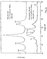
- FIG. 1a is an X-ray diffraction diagram illustrating the peaks of Pt and Ru of a Pt and Ru catalyst prepared as described in Comparative Example 1 and those of a catalyst of the same type supported on carbon black and prepared as described in example 3.
- FIG. 1b is an X-ray diffraction diagram illustrating the peaks of Pt and Ru of a catalyst based on Pt and Ru supported on carbon black and prepared as described in Comparative Example 2 and those of a catalyst of the same type supported on black of carbon and prepared as described in Example 3.
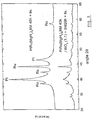
- FIG. 2 is an X-ray diffraction diagram illustrating the peaks of Pt and Ru of a catalyst based on Pt and Ru prepared as described in Comparative Example 1 and those of a catalyst of the same type supported on WO 3 and prepared as described in Example 5.
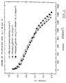
- FIG. 3 illustrates the polarization curves under pure H 2 of PtRu (MgH 2 ) 8 BM40h / WO 3 (1: 1at) + BM20h + lix prepared as described in Example 5, of PtRu (MgH 2 ) 8 BM40h + lix as prepared in Example 1, and of PtRuBlack (Johnson-Matthey®).
- FIG. 4 illustrates the polarization curves obtained under H 2 +100 ppm CO for the same catalysts as in FIG. 3.
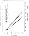
- FIG. 5 illustrates the polarization curves obtained under pure H 2 for the 20% PtRu (MgO) 8 BM40h / XC-72R + lix as prepared in Example 3, the PtRu (MgO) 8 BM40h + lix as prepared in Example 1, 20% PtRuBM40h / XC-72R as prepared in Example 2, and 20% PtRu / XC-72 (E-Tek®).
- FIG. 6 illustrates polarization curves obtained under H 2 +100 ppm CO for the same catalysts as in Example 5.
- FIG. 7 illustrates the polarization curves obtained under pure H 2 for the 20% PtRu (MgO) 8 BM40h + XC-72R + lix prepared as described in Example 4, the PtRu (MgO) 8 BM40h + lix prepared as as described in Comparative Example 1, and 20% PtRu / XC-72 (E-Tek®).
- FIG. 8 illustrates the polarization curves obtained under H 2 +100 ppm CO for the same catalysts as in Example 7.
- FIG. 9 is a photograph obtained by scanning electron microscopy of the surface of a sample of the prior art, PtRu (MgO) 8 BM40h + lix, at a magnification of 30,000 times, in secondary electron mode.
- Figure 10 is a photograph similar to that of Figure 9 but in of backscattered electrons.
- Figure 11 is a photograph of the surface of the same sample, PtRu (MgO) 8 BM40h + lix, at a magnification of 100,000 times, in secondary electron mode.
- Figure 12 is a photograph of the surface of a 20% PtRu (MgO) 8 BM40h / XC-72R + lix sample at 30,000x magnification, in secondary electron mode.
- Figure 13 is a photograph similar to that of Figure 12 but in of backscattered electrons.
- Figure 14 is a photograph of the surface of the same sample, 20% PtRu (MgO) 8 BM40h / XC-72R + lix, at a magnification of 100,000 times in secondary electron mode.
- Figure 15 is a photograph similar to that of Figure 14 but in of backscattered electrons.
- the invention relates to a process for the manufacture of supported catalysts of nanocrystalline structure and of specific surface preferably greater than 2 m 2 / g, comprising a first step of intense mechanical grinding coupled with a second step of leaching.
- the catalytic species or species used contain at least one element chosen from the group consisting of Pd, Pt, Ir, Os, Au, Rh, Ag, Ru, Ni.
- the non-leachable chemical compound or elements capable of serving as a support are chosen from those having a large area specific and good electronic conduction.
- such compounds or chemical elements there may be mentioned carbon black, graphite, doped zeolites, pyrolyzed polyacrylonitriles, carbides and conductive oxides.
- the non-leachable chemical compound or elements capable of serving as a support are chosen from those having a large area specific and good ionic conduction.
- such compounds or elements include ionomeric conductive polymers and ceramics conductive of ions.
- These compounds or non-leachable elements serve as dispersants and as supports for catalytic species. However, they can also serve as supplements during the catalysis reaction and, for example, improve the CO tolerance of electrocatalysis materials (eg WO 3 brought into contact with Pt).
- the chemical compounds or elements serving as support are used in quantities such as to have a molar concentration greater than 50% in the supported catalyst manufactured.
- the compound or compounds or leachable chemical elements in the second step include at least one non-metallic element chosen from the group consisting of H, C, N, O, F, Cl, P and S; and the leaching of this or these elements is performed by thermal decomposition or by reaction with another phase.
- the chemical compound (s) or leachable in the second step are chosen from the group consisting, on the one hand, of Mg, Li, Na, K, Ca, Ti, Zr and Zn and, on the other hand, the non-metallic elements H, C, N, O, F, Cl, P and S; and the leaching of this or these elements is carried out by thermal decomposition or by reaction with another phase.
- the leachable chemical compounds or elements have a molar concentration greater than or equal to 2% and less than or equal to 95% relative to in total of all chemical compounds or elements used.
- the nanocrystalline material is prepared in powder form by a mixture of all the compounds or elements chemicals used as starting materials, followed by a single intense mechanical grinding.
- all of the compounds are mixed or chemical elements used as starting materials except the compound (s) or chemical elements used as supports to obtain a first mixture and we proceed to a first intense mechanical grinding of this first mixture.
- all of the compounds are mixed or chemical elements used as starting materials except the compound (s) or chemical elements serving as carriers and the chemical compound or elements leachable to obtain a first mixture.
- the first step therefore comprises one, two or three successive grindings.
- the second process step which consists in leaching the powder obtained to dissolve partially or totally the leachable chemical compound (s) or element (s).
- the compound (s) or elements chemicals used as a support are added only during the second stage of leaching, this addition being made to the leaching solution, and the solution leaching is subjected to mechanical, magnetic and / or ultrasonic agitation.
- the leachable or non-leachable chemical compounds or elements which are used as starting materials can be ground beforehand before being used.
- the supported catalyst obtained can be a nanocomposite, a solid solution, an intermetallic or a combination of these.
- This catalyst can be made of several elements (eg a nanocomposite comprising MoO 3 + WO 3 + PtRu + RuO 2 + Pd).
- the total amount of powder to be ground was around 7-8g and the number of beads added was chosen to obtain a weight of approximately 40g, and this for a ratio beads / powder of 5 by weight.
- the grinding lasted 40 hours, i.e. until none no change is observed in the crystal structure.
- the leaching step then been undertaken with the ground powder. This was placed in 300 mL of HCl solution 1M with magnetic stirring for 8 hours or more. The resulting solution then been filtered in a filter paper and funnel by gravitation, rinse with distilled water, then dry in an oven in air for about 8 hours until the water evaporates.
- Comparative example 2 synthesis of PtRu supported on carbon black, without leaching
- a PtRu alloy was produced by a first intense mechanical grinding. This alloy was then subjected to a second grinding in presence of carbon black. The concentration of PtRu relative to carbon was 20% by weight.
- the resulting powder will hereinafter be denoted 20% PtRu BM40h / XC-72R.
- Example 3 synthesis of PtRu supported on carbon black with leaching
- PtRu (MgO) 8 BM40h was prepared by operating as described in Comparative Example 1 except that the product obtained was not immediately leached.
- PtRu (MgO) 8 BM40h obtained and carbon black (XC-72R) were placed, in a ratio totaling 20% by weight of PtRu on carbon.
- the resulting product after grinding will be denoted PtRu (MgO) 8 BM-40h / XC-72R.
- the total amount of powder to be ground was around 1.4g and the number of beads added was chosen to total a weight of approximately 15g, and this for a ratio beads / powders of 10 by weight.
- the grinding was 20 hours. Once ground, the powder was placed in 300 ml of 1M HCl solution with magnetic stirring for 8 hours. The resulting solution was then filtered through filter paper and funneled gravitation, rinse with distilled water, then dry in an oven in air for about 8 hours until the water evaporates.
- Example 4 synthesis of PtRu dispersed on carbon black with leaching
- PtRu (MgO) 8 BM40h was prepared by operating as described in Comparative Example 1, except that at the leaching stage, carbon black is added to the 1M HCl solution. PtRu (MgO) 8 BM40h was added to the solution in a ratio totaling approximately 20% by weight of PtRu on carbon. The product obtained according to this synthesis will hereinafter be denoted PtRu (MgO) 8 BM40h + XC-72R.
- Example 5 synthesis of PtRu dispersed on WO 3 with leaching
- PtRu (MgH 2 ) 8 BM40h was prepared by operating as described in Example 1 except that the product obtained was not immediately leached. In a crucible in WC, with 2, 3 or 4 balls in WC, under argon, the PtRu (MgH 2 ) 8 BM40h and the WO 3 were placed in an atomic ratio of 1: 1. The result after grinding was denoted PtRu (MgH 2 ) 8 BM40h / WO 3 .
- the total amount of powder to be ground was around 7g and the number of beads added was chosen to total a weight of approximately 40g, and this for a ratio beads / powders of almost 6 by weight.
- the grinding was 20 hours. Once ground, the powder was placed in 300 mL of 1M HCl solution with magnetic stirring for more than 8 hours. The resulting solution was then filtered through filter paper and funnel by gravitation, rinse with distilled water, then dry in an oven under air for 8 about hours until the water evaporates.
- the specific surface of the ground Pt is low: 0.25 m 2 / g. If we grind Pt and Ru (1: 1 at) together for 40 hours under Ar, the crystallite size is 10.5 nm and the specific surface almost doubles compared to the ground Pt: (0.45 m 2 / g) but still remains very low. From these experiences, we can deduce the following point.
- the size of the crystallites should not be considered as proportional to the specific surface. Although a size of crystallites of the order of a few nanometers is an essential condition for obtaining particles of similar size, there is a phenomenon of cold welding which takes place between the crystallites during mechanical grinding, this which increases the size of the particles.
- PtRuBM40h crystallites goes from 10.5 nm to 8.8 nm if we follow the procedure of the prior art, example 1. It is also interesting to observe that the size of the crystallites of PtRuBM40h goes from 10.5 nm to 7.9 nm if it is dispersed by mechanical grinding for 20 hours with carbon black, PtRuBM40h / XC-72 (20% by weight PtRu / C) + BM20h (prior art, example 2).
- the process of the present invention makes it possible to reduce the size of the crystallites more than all of the previous methods of the prior art, whether this is the process described in Example 1, where the size of the crystallite increases from 10.5 nm at 8.8 nm with PtRu (MgO) 8 BM40h + lix., or that described in Example 2, where the crystallite size goes from 10.5 nm to 7.9 nm with PtRuBM40h / XC-72 (20% by weight PtRu / C) + BM20h. There is therefore a synergistic effect when the two methods are used.
- the specific surface of the dispersed catalyst PtRu (MgO) 8 BM40h / XC-72 (20% by weight PtRu / C) + BM20h-lix. according to the invention is 92.77 m 2 / g while that of the commercial catalyst PtRu / XC-72 20wt% (E-Tek®) is 148.70 m 2 / g.
- This 50% difference is probably due to a decrease in the surface area of the carbon black (XC-72R) during mechanical grinding, possibly due to the closing of certain pores in the carbon black.
- Figs 1a, 1b and 2 clearly show the widening of the Pt peaks when the dispersion treatment with the non-leachable agent is applied.
- the signal from PtRu (MgO) 8 BM40h / XC-72 (20% by weight PtRu / C) + BM20h + lix. according to the invention is smaller, it is noted that the width at mid-height of the peaks of Pt is greater than that of PtRu (MgO) 8 BM40h + lix, which indicates a smaller crystallite size. The same phenomenon is observed in fig.
- Tests were carried out on the supported catalysts according to the invention., More specifically, fuel cell tests were carried out in a 5 cm 2 cell, from the company GlobeTech. A membrane-electrode assembly (AME) was prepared in this cell prepared as follows.
- the cathode came from the company E-Tek® and was made of a fabric impregnated with carbon black and very fine particles of Teflon®. On one of the surfaces was deposited a commercial electrocatalyst composed of fine particles of Pt adsorbed on carbon black. The trademark of this catalyst is "catalyzed Elat®" and it has a Pt load of 0.35-0.40 mg / cm 2 . A layer of Nafion® in soluble form was deposited on the surface of the cathode and dried to give a weight of 0.6 mg Nafion / cm 2 .
- the anode was prepared by making an ink containing the catalyst. This ink was deposited on the surface of another carbon fabric impregnated with Teflon® without catalyst, "uncatalyzed Elat®", to give a load of 4 mg / cm 2 of catalyst.
- an ink was prepared by ultrasonic shaking in a closed bottle for 40 to 50 minutes, 40 mg of catalyst, 150 ⁇ L of Nafion ® in solution (Aldrich, 5% by weight), 100 ⁇ L of deionized water, 300 ⁇ L of electronic grade methanol and 60 ⁇ L of glycerin. 305 ⁇ L of this solution was pipetted and deposited on the surface of the carbon tissue. This electrode was then dried under vacuum for 2 hours at approximately 100 ° C.
- the charge was 0.4 mg / cm 2 .
- the ink was prepared by ultrasonic shaking in a closed bottle for 40 to 50 minutes, 17.5 mg of catalyst, 370 ⁇ L of Nafion ® in solution, 200 ⁇ L of electronic grade methanol and 60 ⁇ L of glycerin. 315 ⁇ L of this solution is pipetted and deposited on the surface of the carbon fabric. This electrode was then dried under vacuum for 2 hours at approximately 100 ° C.
- the membrane was then pressed between the anode and the cathode using a press hot at 140 ° C, for 40 seconds at a pressure of 2500 pounds.
- the tests were carried out with pure hydrogen and pure oxygen. After the tests under pure hydrogen, a hydrogen gas containing 100 ppm CO was used to check the CO tolerance. This gas was passed through the open circuit cell for 30 minutes before the first measurements.
- Fig. 3 shows the polarization curves under pure H 2 of PtRu (MgH 2 ) 8 BM40h / WO 3 (1: 1 at) + BM20h + lix. (example 5) compared to PtRu (MgH 2 ) 8 BM40h + lix. (prior art - example 1) and at PtRuBlack (Johnson-Matthey). The latter is slightly higher in activity than the other two. However, since the catalyst charge is the same for all the anodes tested, there is 22% less PtRu by weight in the PtRu (MgH 2 ) 8 BM40h / WO 3 (1: 1 at) + MB20h + lix. according to the invention as for the other catalysts. The invention therefore succeeds in reducing the quantity of noble metal while retaining approximately the same catalytic activity.
- Fig. 4 shows the polarization curves obtained under H 2 +100 ppm CO for the same catalysts. All are affected by the presence of CO, but they demonstrate almost all the same performance.
- PtRu there is less PtRu by weight in PtRu (MgH 2 ) 8 BM40h / WO 3 (1: 1 at) + BM20h + lix. according to the invention than in the other catalysts.
- Fig. 5 shows the polarization curves obtained under pure H 2 for 20% PtRu (MgO) 8 BM40h / XC-72R + lix. compared to PtRu (MgO) 8 BM40h + lix., at 20% PtRuBM40h / XC-72R (prior art, example 2) and at 20% PtRu / XC-72 (E-Tek®). There are relatively comparable catalytic activities for all the catalysts, especially at the potential greater than 0.5V.
- the 20% PtRu (MgO) 8 BM40h / XC-72R + lix. uses less PtRu than PtRu (MgO) 8 BM40h + lix. for similar performance.
- Fig. 6 shows the polarization curves obtained under H 2 +100 ppm CO for the same catalysts.
- the commercial catalyst 20% PtRu / XC-72 (E-Tek®) is slightly less affected than the other two, although the latter are not far away.
- the argument for saving PtRu in the 20% PtRu (MgO) 8 BM40h / XC-72R + lix. according to the invention compared to PtRu (MgO) 8 BM40h + lix, (prior art - example 1) remains valid.
- the 20% PtRuBM40h / XC-72R catalyst (prior art - example 2) shows performances clearly lower than those offered by the others. This demonstrates, at equal concentration of PtRu, the advantage of the new manufacturing process compared to that of the prior art - example 2.
- Fig. 7 shows the polarization curves obtained under pure H 2 for 20% PtRu (MgO) 8 BM40h + XC-72R + lix. according to the invention compared to PtRu (MgO) 8 BM40h + lix. and 20% PtRu / XC-72 (E-Tek®).
- the catalytic activities being relatively comparable for these catalysts, it is deduced therefrom that the process according to the invention where the non-leachable compounds are added at the leaching stage give products comparable to the others (FIG. 5 vs FIG. 7).
- Fig. 8 shows the polarization curves obtained under H 2 +100 ppm CO for the same catalysts. This time, at 0.5 V, the 20% PtRu (MgO) 8 BM40h + XC-72R + lix. according to the invention shows less satisfactory results than in FIG. 6. Nevertheless, the performances all the same demonstrate that the preparation process remains valid.
- the products prepared in the examples were analyzed with a microscope Hitachi® S-4700 scanning electronics.
- Fig. 9 shows the surface of a sample of the prior art, PtRu (MgO) 8 BM40h + lix. (example 1), at a magnification of 30,000 times, in secondary electron mode. The surface is very porous and the size of these pores is much less than 1 ⁇ m.
- Fig. 10 is the same, but taken in backscattered electron mode. The uniformity of intensity indicates a homogeneous chemical composition.
- Fig. 11 shows the surface of the same sample, PtRu (MgO) 8 BM40h + lix., At a magnification of 100,000 times, in secondary electron mode. There is a large amount of pores of about 10 nm and less. So this structure is like a sponge with nanometric pores.
- Fig. 12 shows the surface of the 20% PtRu (MgO) 8 BM40h / XC-72R + lix sample. according to the invention (example 3) at a magnification of 30,000 times, in secondary electron mode.
- the presence of carbon black (XC-72R) drastically changes the morphology. Indeed, unlike fig. 9, where only the Pt-Ru nanocomposite is present, practically only the rounded forms of carbon black are seen.
- fig. 13 backscattered electron mode
- Fig. 14 shows a 100,000-fold magnification of the surface of the same sample, 20% PtRu (MgO) 8 BM40h / XC-72R + lix., In secondary electron mode. The rounded forms of carbon black are still observed there. In backscattered electron mode (fig. 15), particles of Pt and Ru of the order of 10 nm and less dispersed on carbon black are easily observed. Thus, it can be seen that these particles are of the size of the crystallites, that is to say of the order of approximately 5 nm, as measured in XRD. This means that the manufacturing process according to the invention manages to separate the crystallites practically one by one.
Landscapes
- Chemical & Material Sciences (AREA)
- Chemical Kinetics & Catalysis (AREA)
- General Chemical & Material Sciences (AREA)
- Catalysts (AREA)
- Inert Electrodes (AREA)
Claims (18)
- Verfahren zur Herstellung eines Katalysators, geträgert von einer nanokristallinen Struktur und mit großer spezifischer Oberfläche, worin:dadurch gekennzeichnet, dass die oder das mindestens eine nicht auslaugbare, chemische Verbindung oder Element, das zum Trägern der katalytischen Spezies dient, dem Material im ersten. Schritt oder der Auslauglösung im zweiten Schritt zugesetzt wird.man in einem ersten Schritt ein nanokristallines Material herstellt, bestehend aus einem Verbundstoff oder einer metastabilen Legierung mindestens zweier Verbindungen oder chemisch verschiedener Elemente, enthaltend mindestens eine katalytische Spezies, wobei das so hergestellte Material eine nanokristalline Struktur mit Kristallen einer Größe kleiner als 100 nm aufweist; undman in einem zweiten Schritt das besagte nanokristalline Material einer Auslaugung durch eine Lösung zur Auslaugung unterwirft, um mindestens eine der besagten Verbindungen oder Elemente des Materials, anders als die katalytische(n) Spezies, teilweise oder vollständig zu eliminieren;
- Verfahren nach Anspruch 1, dadurch gekennzeichnet, dass das oder die chemische(n) Verbindung(en) oder Element(e), die zum Trägern dienen, eine große spezifische Oberfläche und eine gute elektrische Leitfähigkeit aufweisen.
- Verfahren nach Anspruch 1, dadurch gekennzeichnet, dass das oder die chemische(n) Verbindung(en) oder Element(e), die zum Trägern dienen, ausgewählt sind aus der Gruppe, bestehend aus Ruß, Graphit, dotiertemZeolith, pyrolysierten Polyacrylnitrilen, den Carbiden und Oxiden.
- Verfahren nach Anspruch 1, dadurch gekennzeichnet, dass das oder die chemische(n) Verbindung(en) oder Element(e), die als Träger dienen, eine große spezifische Oberfläche und eine gute ionische Leitfähigkeit aufweisen.
- Verfahren nach Anspruch 1, dadurch gekennzeichnet, dass das oder die chemische(n) Verbindung(en) oder Element(e), die als Träger dienen, ausgewählt sind aus der Gruppe, bestehend aus polymeren Ionenleitern und keramischen Ionenleitern.
- Verfahren nach Anspruch 1, dadurch gekennzeichnet, dass das oder die chemische(n) Verbindung(en) oder Element(e), die als Träger dienen, in Form von Pulver, Gitter, Blättchen, eines Films oder von Plaques vorliegen.
- Verfahren nach einem der Ansprüche 1 bis 6, dadurch gekennzeichnet, dass die eine oder die katalytischen Spezies, die verwendet werden, mindestens ein Element enthalten, ausgewählt aus der Gruppe, bestehend aus Pd, Pt, Ir, Os, Au, Rh, Ag, Ru und Ni.
- Verfahren nach einem der Ansprüche 1 bis 7, dadurch gekennzeichnet, dass:das oder die chemischen Verbindungen oder Elemente, die in dem zweiten Schritt ausgelaugt werden, mindestens ein nicht-metallisches Element umfassen, ausgewählt aus der Gruppe, bestehend aus H, C, N, O, F, Cl, P und S; unddie Auslaugung des oder der Elemente durch thermische Zersetzung oder Reaktion mit einer anderen Phase bewirkt wird.
- Verfahren nach einem der Ansprüche 1 bis 7, dadurch gekennzeichnet, dass:das oder die chemische(n) Verbindung(en) oder Element(e), die in dem zweiten Schritt ausgelaugt werden, ausgewählt sind aus der Gruppe, bestehend zum einen aus Mg, Li, Na, K, Ca, Ti, Zr und Zn und zum anderen aus den nicht-metallischen Elementen H, C, N, O, F, Cl, P und S; unddie Auslaugung des oder der Elemente durch thermische Zersetzung oder Reaktion mit einer anderen Phase bewirkt wird.
- Verfahren nach einem der Ansprüche 1 bis 9, dadurch gekennzeichnet, dass das oder die auslaugbare(n) chemische(n) Verbindung(en) oder Element(e) in einer Molkonzentration oberhalb oder gleich 2 % und unterhalb oder gleich 95 % vorhanden sind, bezogen auf das Gesamte aller verwendeten chemischen Verbindungen oder Elemente.
- Verfahren nach einem der Ansprüche 1 bis 10, dadurch gekennzeichnet, dass in dem ersten Schritt das nanokristalline Material in Form eines Pulvers hergestellt wird durch Mischen aller chemischen Verbindungen oder Elemente, die als Ausgangsprodukte verwendet werden, gefolgt von einer einzigen intensiven mechanischen Zerkleinerung.
- Verfahren nach einem der Ansprüche 1 bis 10, dadurch gekennzeichnet, dass man in dem ersten Schritt:alle chemischen Verbindungen oder Elemente, die als Ausgangsprodukte verwendet werden, bis auf das oder die chemische(n) Verbindung(en) oder Element(e) mischt, die als Träger dienen, um eine erste Mischung zu erhalten, und man mit einer ersten intensiven mechanischen Zerkleinerung dieser ersten Mischung fortfährt; undman das oder die chemische(n) Verbindung(en) oder Element(e) zugibt, die als Träger dienen, um eine zweite Mischung zu erhalten, und man mit einer zweiten mechanischen intensiven Zerkleinerung dieser zweiten Mischung fortfährt.
- Verfahren nach einem der Ansprüche 1 bis 10, dadurch gekennzeichnet, dass man in dem ersten Schritt:alle als Ausgangsprodukte verwendeten chemischen Verbindungen oder Elemente mischt bis auf das oder die chemischen Verbindungen oder Elemente, die als Träger dienen, sowie das oder die chemischen auslaugbaren Verbindungen oder Elemente zum Erhalt einer ersten Mischung, und man mit einer ersten mechanischen intensiven Zerkleinerung dieser ersten Mischung fortfährt; undman zur ersten zerkleinerten Mischung das oder die chemischen auslaugbaren Verbindungen oder Elemente hinzu gibt zum Erhalt einer zweiten Mischung und mit einer zweiten mechanischen intensiven Zerkleinerung der zweiten Mischung fortfährt; undman zu der zweiten zerkleinerten Mischung das oder die chemischen Verbindungen oder Elemente hinzu gibt, die als Träger dienen, zum Erhalt einer dritten Mischung und mit einer dritten mechanischen intensiven Zerkleinerung dieser dritten Mischung fortfährt.
- Verfahren nach einem der Ansprüche 1 bis 10, dadurch gekennzeichnet, dass:das oder die chemische(n) Verbindung(en) oder Element(e), die als Träger dienen, nur während des zweiten Schritts der Auslaugung zugegeben werden, wobei diese Zugabe durch die Auslauglösung bewirkt wird; unddie Auslauglösung einem mechanischen, magnetischen und/oder Ultraschallrühren unterworfen wird.
- Verfahren nach einem der Ansprüche 1 bis 14, dadurch gekennzeichnet, dass das oder die chemische(n) Verbindung(en) oder Element(e), die als Träger dienen, in einer solchen Menge verwendet werden, dass sie in einer molaren Konzentration oberhalb von 50 % in dem einmal hergestellten geträgerten Katalysator vorhanden sind.
- Katalysator, geträgert auf nanokristalliner Struktur, dadurch gekennzeichnet, dass:er eine spezifische Oberfläche oberhalb von 2 m2/g aufweist; under über ein Verfahren gemäß einem der Ansprüche 1 bis 15 hergestellt werden kann.
- Verwendung eines geträgerten Katalysators, wie er in Anspruch 16 definiert ist, als Elektrokatalysator in einem Verbrennungsreaktor.
- Verwendung eines geträgerten Katalysators, wie er in Anspruch 16 definiert ist, als Elektrokatalysator in einem Elektrolysegerät.
Applications Claiming Priority (3)
| Application Number | Priority Date | Filing Date | Title |
|---|---|---|---|
| US218138 | 1998-12-22 | ||
| US09/218,138 US6239065B1 (en) | 1998-12-22 | 1998-12-22 | Process for the preparation of a supported catalyst |
| PCT/CA1999/001165 WO2000037173A1 (fr) | 1998-12-22 | 1999-12-03 | Procede de fabrication d'un catalyseur supporte |
Publications (2)
| Publication Number | Publication Date |
|---|---|
| EP1144111A1 EP1144111A1 (de) | 2001-10-17 |
| EP1144111B1 true EP1144111B1 (de) | 2002-08-28 |
Family
ID=22813902
Family Applications (1)
| Application Number | Title | Priority Date | Filing Date |
|---|---|---|---|
| EP99957801A Expired - Lifetime EP1144111B1 (de) | 1998-12-22 | 1999-12-03 | Verfahren zur herstellung eines trägerkatalysators |
Country Status (8)
| Country | Link |
|---|---|
| US (1) | US6239065B1 (de) |
| EP (1) | EP1144111B1 (de) |
| JP (1) | JP3732410B2 (de) |
| AT (1) | ATE222804T1 (de) |
| AU (1) | AU1541800A (de) |
| CA (1) | CA2341610C (de) |
| DE (1) | DE69902694T2 (de) |
| WO (1) | WO2000037173A1 (de) |
Families Citing this family (14)
| Publication number | Priority date | Publication date | Assignee | Title |
|---|---|---|---|---|
| JP4446029B2 (ja) * | 2000-03-31 | 2010-04-07 | 独立行政法人物質・材料研究機構 | メタノール水蒸気改質用触媒の製造方法 |
| US20020155342A1 (en) * | 2001-04-06 | 2002-10-24 | Ballard Power Systems Inc. | High utilization supported catalyst compositions with improved resistance to poisoning and corrosion |
| EP1254711A1 (de) * | 2001-05-05 | 2002-11-06 | OMG AG & Co. KG | Edelmetallhaltiger Trägerkatalysator und Verfahren zu seiner Herstellung |
| KR100512451B1 (ko) * | 2002-02-28 | 2005-09-05 | (주)에프이에이 코퍼레이션 | 자성체 나노입자에 지지된 재사용가능한 유기금속촉매 및 그 제조방법 |
| WO2003079470A1 (en) * | 2002-03-20 | 2003-09-25 | Matsushita Electric Industrial Co., Ltd. | Fuel cell |
| CN100397688C (zh) * | 2002-07-29 | 2008-06-25 | 科内尔研究基金会有限公司 | 作为催化剂和催化系统使用的金属互化物 |
| US6695986B1 (en) | 2002-09-25 | 2004-02-24 | The United States Of America As Represented By The Secretary Of The Navy | Electrocatalytic enhancement with catalyst-modified carbon-silica composite aerogels |
| WO2004043591A1 (en) | 2002-11-07 | 2004-05-27 | Tufts University | Catalyst having metal in reduced quantity and reduced cluster size |
| JP4207120B2 (ja) * | 2003-04-08 | 2009-01-14 | ソニー株式会社 | 触媒電極並びに電気化学デバイス |
| KR100766931B1 (ko) | 2005-08-31 | 2007-10-17 | 삼성에스디아이 주식회사 | 연료 전지의 캐소드 전극용 촉매, 이를 포함하는 연료전지용 막-전극 어셈블리 및 이를 포함하는 연료 전지시스템 |
| EP1772916A3 (de) * | 2005-08-31 | 2009-01-28 | Samsung SDI Co., Ltd. | Kathodenkatalysator für Brennstoffzelle und Membran-Elektroden-Anordnung |
| US20090215615A1 (en) * | 2006-07-11 | 2009-08-27 | 3M Innovative Properties Company | Method of forming supported nanoparticle catalysts |
| WO2010142350A1 (en) * | 2009-06-12 | 2010-12-16 | Aggregate Energy, Llc. | Catalyst comprising a metal and a supplemental component and process for hydrogenating oxygen containing organic products |
| US20110020735A1 (en) * | 2009-07-23 | 2011-01-27 | Ford Global Technologies, Llc | Fuel Cell Catalysts with Enhanced Catalytic Surface Area and Method of Making the Same |
Family Cites Families (8)
| Publication number | Priority date | Publication date | Assignee | Title |
|---|---|---|---|---|
| US1638190A (en) | 1925-06-12 | 1927-08-09 | Zeiss Carl Fa | Device for the mechanical multiplication of two factors |
| DE1671710A1 (de) * | 1967-05-30 | 1971-09-23 | Bosch Gmbh Robert | Verfahren zur Herstellung von Elektroden mit Raney-Katalysatoren fuer Brennstoffzellen |
| US4186110A (en) * | 1978-07-03 | 1980-01-29 | United Technologies Corporation | Noble metal-refractory metal alloys as catalysts and method for making |
| JPS56124447A (en) * | 1980-03-05 | 1981-09-30 | Hitachi Ltd | Manufacture of catalyst |
| TW340806B (en) | 1995-03-28 | 1998-09-21 | Mitsui Toatsu Chemicals | Modified Raney catalyst and process for preparation thereof |
| JP3874380B2 (ja) * | 1996-08-26 | 2007-01-31 | エヌ・イーケムキャット株式会社 | 空格子点型格子欠陥を有するカーボン担持白金スケルトン合金電極触媒 |
| GB9622284D0 (en) * | 1996-10-25 | 1996-12-18 | Johnson Matthey Plc | Improved catalyst |
| US5872074A (en) | 1997-01-24 | 1999-02-16 | Hydro-Quebec | Leached nanocrystalline materials process for manufacture of the same, and use thereof in the energetic field |
-
1998
- 1998-12-22 US US09/218,138 patent/US6239065B1/en not_active Expired - Fee Related
-
1999
- 1999-12-03 CA CA002341610A patent/CA2341610C/fr not_active Expired - Fee Related
- 1999-12-03 WO PCT/CA1999/001165 patent/WO2000037173A1/fr not_active Ceased
- 1999-12-03 AT AT99957801T patent/ATE222804T1/de not_active IP Right Cessation
- 1999-12-03 EP EP99957801A patent/EP1144111B1/de not_active Expired - Lifetime
- 1999-12-03 JP JP2000589277A patent/JP3732410B2/ja not_active Expired - Fee Related
- 1999-12-03 AU AU15418/00A patent/AU1541800A/en not_active Abandoned
- 1999-12-03 DE DE69902694T patent/DE69902694T2/de not_active Expired - Lifetime
Also Published As
| Publication number | Publication date |
|---|---|
| JP2002532247A (ja) | 2002-10-02 |
| EP1144111A1 (de) | 2001-10-17 |
| ATE222804T1 (de) | 2002-09-15 |
| WO2000037173A1 (fr) | 2000-06-29 |
| AU1541800A (en) | 2000-07-12 |
| DE69902694T2 (de) | 2003-05-28 |
| US6239065B1 (en) | 2001-05-29 |
| JP3732410B2 (ja) | 2006-01-05 |
| CA2341610C (fr) | 2004-04-06 |
| DE69902694D1 (de) | 2002-10-02 |
| CA2341610A1 (fr) | 2000-06-29 |
Similar Documents
| Publication | Publication Date | Title |
|---|---|---|
| Zhu et al. | Highly stable Pt-Co nanodendrite in nanoframe with Pt skin structured catalyst for oxygen reduction electrocatalysis | |
| EP1144111B1 (de) | Verfahren zur herstellung eines trägerkatalysators | |
| Wang et al. | Novel flower-like PdAu (Cu) anchoring on a 3D rGO-CNT sandwich-stacked framework for highly efficient methanol and ethanol electro-oxidation | |
| US10950870B2 (en) | Method for producing alloy catalyst for fuel cells using silica coating | |
| JP4490510B2 (ja) | 浸出微結晶材料、その製造方法、及びエネルギー分野におけるその使用方法 | |
| Sandhiran et al. | CuO–NiO binary transition metal oxide nanoparticle anchored on rGO nanosheets as high-performance electrocatalyst for the oxygen reduction reaction | |
| Li et al. | PdCoNi alloy nanoparticles decorated, nitrogen-doped carbon nanotubes for highly active and durable oxygen reduction electrocatalysis | |
| US20190276943A1 (en) | Carbon supported single atom carbon dioxide reduction electro catalysts | |
| US10186711B2 (en) | Photocatalytic methods for preparation of electrocatalyst materials | |
| CA2256827A1 (en) | Anode catalyst for fuel cells with polymer electrolyte membranes | |
| Liu et al. | Oxygen reduction catalyzed by nanocomposites based on graphene quantum dots-supported copper nanoparticles | |
| US20120094199A1 (en) | Catalyst for electrochemical applications | |
| Huang et al. | A facile approach for preparation of highly dispersed platinum-copper/carbon nanocatalyst toward formic acid electro-oxidation | |
| KR101649384B1 (ko) | 촉매의 연속 제조 방법 | |
| Cao et al. | Composition-tunable PtCu porous nanowires as highly active and durable catalyst for oxygen reduction reaction | |
| Ren et al. | Electro-catalytic performance of Pd decorated Cu nanowires catalyst for the methanol oxidation | |
| US20060251953A1 (en) | Photocatalytic methods for preparation of electrocatalyst materials | |
| Stamatelos et al. | Ternary Zn-Ce-Ag catalysts for selective and stable electrochemical CO2 reduction at large-scale | |
| Martins et al. | PdNi alloy nanoparticles assembled on cobalt ferrite-carbon black composite as a fuel cell catalyst | |
| Ju et al. | Ultrafine IrMnO x Nanocluster Decorated Amorphous PdS nanowires as efficient electrocatalysts for high C1 selectivity in the alkaline ethanol oxidation reaction | |
| Shamraiz et al. | Low cost efficient Sr (OH) 2 promoted Pd/rGO electrocatalyst for direct alcohol fuel cell | |
| JP2012245461A (ja) | 触媒微粒子の製造方法、及びカーボン担持触媒微粒子の製造方法 | |
| Sofian et al. | Efficient formic acid oxidation over gallium oxide incorporated Pd containing electrocatalyst | |
| EP3605681A1 (de) | Katalysatorträger-kohlenstoffmaterial für eine festpolymer-brennstoffzelle und herstellungsverfahren dafür | |
| Poochai et al. | Dealloyed ternary Cu@ Pt-Ru core-shell electrocatalysts supported on carbon paper for methanol electrooxidation catalytic activity |
Legal Events
| Date | Code | Title | Description |
|---|---|---|---|
| PUAI | Public reference made under article 153(3) epc to a published international application that has entered the european phase |
Free format text: ORIGINAL CODE: 0009012 |
|
| 17P | Request for examination filed |
Effective date: 20010608 |
|
| AK | Designated contracting states |
Kind code of ref document: A1 Designated state(s): AT BE CH CY DE DK ES FI FR GB GR IE IT LI LU MC NL PT SE |
|
| AX | Request for extension of the european patent |
Free format text: AL;LT;LV;MK;RO;SI |
|
| GRAG | Despatch of communication of intention to grant |
Free format text: ORIGINAL CODE: EPIDOS AGRA |
|
| 17Q | First examination report despatched |
Effective date: 20011203 |
|
| GRAG | Despatch of communication of intention to grant |
Free format text: ORIGINAL CODE: EPIDOS AGRA |
|
| GRAH | Despatch of communication of intention to grant a patent |
Free format text: ORIGINAL CODE: EPIDOS IGRA |
|
| GRAH | Despatch of communication of intention to grant a patent |
Free format text: ORIGINAL CODE: EPIDOS IGRA |
|
| GRAA | (expected) grant |
Free format text: ORIGINAL CODE: 0009210 |
|
| AK | Designated contracting states |
Kind code of ref document: B1 Designated state(s): AT BE CH CY DE DK ES FI FR GB GR IE IT LI LU MC NL PT SE |
|
| PG25 | Lapsed in a contracting state [announced via postgrant information from national office to epo] |
Ref country code: IE Free format text: LAPSE BECAUSE OF FAILURE TO SUBMIT A TRANSLATION OF THE DESCRIPTION OR TO PAY THE FEE WITHIN THE PRESCRIBED TIME-LIMIT Effective date: 20020828 Ref country code: GR Free format text: LAPSE BECAUSE OF FAILURE TO SUBMIT A TRANSLATION OF THE DESCRIPTION OR TO PAY THE FEE WITHIN THE PRESCRIBED TIME-LIMIT Effective date: 20020828 Ref country code: FI Free format text: LAPSE BECAUSE OF FAILURE TO SUBMIT A TRANSLATION OF THE DESCRIPTION OR TO PAY THE FEE WITHIN THE PRESCRIBED TIME-LIMIT Effective date: 20020828 Ref country code: AT Free format text: LAPSE BECAUSE OF FAILURE TO SUBMIT A TRANSLATION OF THE DESCRIPTION OR TO PAY THE FEE WITHIN THE PRESCRIBED TIME-LIMIT Effective date: 20020828 |
|
| REF | Corresponds to: |
Ref document number: 222804 Country of ref document: AT Date of ref document: 20020915 Kind code of ref document: T |
|
| REG | Reference to a national code |
Ref country code: GB Ref legal event code: FG4D Free format text: NOT ENGLISH |
|
| REG | Reference to a national code |
Ref country code: CH Ref legal event code: EP |
|
| REF | Corresponds to: |
Ref document number: 69902694 Country of ref document: DE Date of ref document: 20021002 |
|
| REG | Reference to a national code |
Ref country code: IE Ref legal event code: FG4D Free format text: FRENCH |
|
| PG25 | Lapsed in a contracting state [announced via postgrant information from national office to epo] |
Ref country code: DK Free format text: LAPSE BECAUSE OF FAILURE TO SUBMIT A TRANSLATION OF THE DESCRIPTION OR TO PAY THE FEE WITHIN THE PRESCRIBED TIME-LIMIT Effective date: 20021128 |
|
| PG25 | Lapsed in a contracting state [announced via postgrant information from national office to epo] |
Ref country code: LU Free format text: LAPSE BECAUSE OF NON-PAYMENT OF DUE FEES Effective date: 20021203 |
|
| PG25 | Lapsed in a contracting state [announced via postgrant information from national office to epo] |
Ref country code: PT Free format text: LAPSE BECAUSE OF FAILURE TO SUBMIT A TRANSLATION OF THE DESCRIPTION OR TO PAY THE FEE WITHIN THE PRESCRIBED TIME-LIMIT Effective date: 20021211 |
|
| GBT | Gb: translation of ep patent filed (gb section 77(6)(a)/1977) |
Effective date: 20021123 |
|
| PG25 | Lapsed in a contracting state [announced via postgrant information from national office to epo] |
Ref country code: CY Free format text: LAPSE BECAUSE OF FAILURE TO SUBMIT A TRANSLATION OF THE DESCRIPTION OR TO PAY THE FEE WITHIN THE PRESCRIBED TIME-LIMIT Effective date: 20021231 |
|
| PG25 | Lapsed in a contracting state [announced via postgrant information from national office to epo] |
Ref country code: ES Free format text: LAPSE BECAUSE OF FAILURE TO SUBMIT A TRANSLATION OF THE DESCRIPTION OR TO PAY THE FEE WITHIN THE PRESCRIBED TIME-LIMIT Effective date: 20030228 |
|
| PG25 | Lapsed in a contracting state [announced via postgrant information from national office to epo] |
Ref country code: MC Free format text: LAPSE BECAUSE OF NON-PAYMENT OF DUE FEES Effective date: 20030701 |
|
| PLBE | No opposition filed within time limit |
Free format text: ORIGINAL CODE: 0009261 |
|
| STAA | Information on the status of an ep patent application or granted ep patent |
Free format text: STATUS: NO OPPOSITION FILED WITHIN TIME LIMIT |
|
| REG | Reference to a national code |
Ref country code: IE Ref legal event code: FD4D Ref document number: 1144111E Country of ref document: IE |
|
| 26N | No opposition filed |
Effective date: 20030530 |
|
| PG25 | Lapsed in a contracting state [announced via postgrant information from national office to epo] |
Ref country code: LI Free format text: LAPSE BECAUSE OF NON-PAYMENT OF DUE FEES Effective date: 20031231 Ref country code: CH Free format text: LAPSE BECAUSE OF NON-PAYMENT OF DUE FEES Effective date: 20031231 |
|
| REG | Reference to a national code |
Ref country code: CH Ref legal event code: PL |
|
| PGFP | Annual fee paid to national office [announced via postgrant information from national office to epo] |
Ref country code: NL Payment date: 20101124 Year of fee payment: 12 |
|
| PGFP | Annual fee paid to national office [announced via postgrant information from national office to epo] |
Ref country code: BE Payment date: 20101126 Year of fee payment: 12 Ref country code: IT Payment date: 20101127 Year of fee payment: 12 Ref country code: SE Payment date: 20101126 Year of fee payment: 12 Ref country code: GB Payment date: 20101201 Year of fee payment: 12 |
|
| PGFP | Annual fee paid to national office [announced via postgrant information from national office to epo] |
Ref country code: FR Payment date: 20110120 Year of fee payment: 12 Ref country code: DE Payment date: 20101208 Year of fee payment: 12 |
|
| BERE | Be: lapsed |
Owner name: *HYDRO-QUEBEC Effective date: 20111231 |
|
| REG | Reference to a national code |
Ref country code: NL Ref legal event code: V1 Effective date: 20120701 |
|
| REG | Reference to a national code |
Ref country code: SE Ref legal event code: EUG |
|
| GBPC | Gb: european patent ceased through non-payment of renewal fee |
Effective date: 20111203 |
|
| REG | Reference to a national code |
Ref country code: FR Ref legal event code: ST Effective date: 20120831 |
|
| REG | Reference to a national code |
Ref country code: DE Ref legal event code: R119 Ref document number: 69902694 Country of ref document: DE Effective date: 20120703 |
|
| PG25 | Lapsed in a contracting state [announced via postgrant information from national office to epo] |
Ref country code: DE Free format text: LAPSE BECAUSE OF NON-PAYMENT OF DUE FEES Effective date: 20120703 Ref country code: BE Free format text: LAPSE BECAUSE OF NON-PAYMENT OF DUE FEES Effective date: 20111231 Ref country code: SE Free format text: LAPSE BECAUSE OF NON-PAYMENT OF DUE FEES Effective date: 20111204 Ref country code: GB Free format text: LAPSE BECAUSE OF NON-PAYMENT OF DUE FEES Effective date: 20111203 |
|
| PG25 | Lapsed in a contracting state [announced via postgrant information from national office to epo] |
Ref country code: IT Free format text: LAPSE BECAUSE OF NON-PAYMENT OF DUE FEES Effective date: 20111203 |
|
| PG25 | Lapsed in a contracting state [announced via postgrant information from national office to epo] |
Ref country code: NL Free format text: LAPSE BECAUSE OF NON-PAYMENT OF DUE FEES Effective date: 20120701 |
|
| PG25 | Lapsed in a contracting state [announced via postgrant information from national office to epo] |
Ref country code: FR Free format text: LAPSE BECAUSE OF NON-PAYMENT OF DUE FEES Effective date: 20120102 |