EP1144875B1 - Lösbare verbindung zweier elemente - Google Patents
Lösbare verbindung zweier elemente Download PDFInfo
- Publication number
- EP1144875B1 EP1144875B1 EP99960789A EP99960789A EP1144875B1 EP 1144875 B1 EP1144875 B1 EP 1144875B1 EP 99960789 A EP99960789 A EP 99960789A EP 99960789 A EP99960789 A EP 99960789A EP 1144875 B1 EP1144875 B1 EP 1144875B1
- Authority
- EP
- European Patent Office
- Prior art keywords
- bolt
- tensioning body
- connection according
- clamping body
- axis
- Prior art date
- Legal status (The legal status is an assumption and is not a legal conclusion. Google has not performed a legal analysis and makes no representation as to the accuracy of the status listed.)
- Expired - Lifetime
Links
- 150000001875 compounds Chemical class 0.000 description 2
- 230000000694 effects Effects 0.000 description 2
- 238000003780 insertion Methods 0.000 description 2
- 230000037431 insertion Effects 0.000 description 2
- 238000004519 manufacturing process Methods 0.000 description 2
- 230000004308 accommodation Effects 0.000 description 1
- 230000001771 impaired effect Effects 0.000 description 1
- 239000000463 material Substances 0.000 description 1
- 239000002023 wood Substances 0.000 description 1
Images

Classifications
-
- F—MECHANICAL ENGINEERING; LIGHTING; HEATING; WEAPONS; BLASTING
- F16—ENGINEERING ELEMENTS AND UNITS; GENERAL MEASURES FOR PRODUCING AND MAINTAINING EFFECTIVE FUNCTIONING OF MACHINES OR INSTALLATIONS; THERMAL INSULATION IN GENERAL
- F16B—DEVICES FOR FASTENING OR SECURING CONSTRUCTIONAL ELEMENTS OR MACHINE PARTS TOGETHER, e.g. NAILS, BOLTS, CIRCLIPS, CLAMPS, CLIPS OR WEDGES; JOINTS OR JOINTING
- F16B12/00—Jointing of furniture or the like, e.g. hidden from exterior
- F16B12/10—Jointing of furniture or the like, e.g. hidden from exterior using pegs, bolts, tenons, clamps, clips, or the like
- F16B12/12—Jointing of furniture or the like, e.g. hidden from exterior using pegs, bolts, tenons, clamps, clips, or the like for non-metal furniture parts, e.g. made of wood, of plastics
- F16B12/20—Jointing of furniture or the like, e.g. hidden from exterior using pegs, bolts, tenons, clamps, clips, or the like for non-metal furniture parts, e.g. made of wood, of plastics using clamps, clips, wedges, sliding bolts, or the like
- F16B12/2009—Jointing of furniture or the like, e.g. hidden from exterior using pegs, bolts, tenons, clamps, clips, or the like for non-metal furniture parts, e.g. made of wood, of plastics using clamps, clips, wedges, sliding bolts, or the like actuated by rotary motion
-
- Y—GENERAL TAGGING OF NEW TECHNOLOGICAL DEVELOPMENTS; GENERAL TAGGING OF CROSS-SECTIONAL TECHNOLOGIES SPANNING OVER SEVERAL SECTIONS OF THE IPC; TECHNICAL SUBJECTS COVERED BY FORMER USPC CROSS-REFERENCE ART COLLECTIONS [XRACs] AND DIGESTS
- Y10—TECHNICAL SUBJECTS COVERED BY FORMER USPC
- Y10S—TECHNICAL SUBJECTS COVERED BY FORMER USPC CROSS-REFERENCE ART COLLECTIONS [XRACs] AND DIGESTS
- Y10S403/00—Joints and connections
- Y10S403/08—Radially acting cam or eccentric
-
- Y—GENERAL TAGGING OF NEW TECHNOLOGICAL DEVELOPMENTS; GENERAL TAGGING OF CROSS-SECTIONAL TECHNOLOGIES SPANNING OVER SEVERAL SECTIONS OF THE IPC; TECHNICAL SUBJECTS COVERED BY FORMER USPC CROSS-REFERENCE ART COLLECTIONS [XRACs] AND DIGESTS
- Y10—TECHNICAL SUBJECTS COVERED BY FORMER USPC
- Y10S—TECHNICAL SUBJECTS COVERED BY FORMER USPC CROSS-REFERENCE ART COLLECTIONS [XRACs] AND DIGESTS
- Y10S403/00—Joints and connections
- Y10S403/12—Furniture type having a rotatable fastener or fastening element that tightens connection
-
- Y—GENERAL TAGGING OF NEW TECHNOLOGICAL DEVELOPMENTS; GENERAL TAGGING OF CROSS-SECTIONAL TECHNOLOGIES SPANNING OVER SEVERAL SECTIONS OF THE IPC; TECHNICAL SUBJECTS COVERED BY FORMER USPC CROSS-REFERENCE ART COLLECTIONS [XRACs] AND DIGESTS
- Y10—TECHNICAL SUBJECTS COVERED BY FORMER USPC
- Y10T—TECHNICAL SUBJECTS COVERED BY FORMER US CLASSIFICATION
- Y10T403/00—Joints and connections
- Y10T403/57—Distinct end coupler
- Y10T403/5706—Diverse serial connections
- Y10T403/5713—Axially cleft coupler
-
- Y—GENERAL TAGGING OF NEW TECHNOLOGICAL DEVELOPMENTS; GENERAL TAGGING OF CROSS-SECTIONAL TECHNOLOGIES SPANNING OVER SEVERAL SECTIONS OF THE IPC; TECHNICAL SUBJECTS COVERED BY FORMER USPC CROSS-REFERENCE ART COLLECTIONS [XRACs] AND DIGESTS
- Y10—TECHNICAL SUBJECTS COVERED BY FORMER USPC
- Y10T—TECHNICAL SUBJECTS COVERED BY FORMER US CLASSIFICATION
- Y10T403/00—Joints and connections
- Y10T403/66—Interfitted members with external bridging piece
-
- Y—GENERAL TAGGING OF NEW TECHNOLOGICAL DEVELOPMENTS; GENERAL TAGGING OF CROSS-SECTIONAL TECHNOLOGIES SPANNING OVER SEVERAL SECTIONS OF THE IPC; TECHNICAL SUBJECTS COVERED BY FORMER USPC CROSS-REFERENCE ART COLLECTIONS [XRACs] AND DIGESTS
- Y10—TECHNICAL SUBJECTS COVERED BY FORMER USPC
- Y10T—TECHNICAL SUBJECTS COVERED BY FORMER US CLASSIFICATION
- Y10T403/00—Joints and connections
- Y10T403/70—Interfitted members
- Y10T403/7005—Lugged member, rotary engagement
-
- Y—GENERAL TAGGING OF NEW TECHNOLOGICAL DEVELOPMENTS; GENERAL TAGGING OF CROSS-SECTIONAL TECHNOLOGIES SPANNING OVER SEVERAL SECTIONS OF THE IPC; TECHNICAL SUBJECTS COVERED BY FORMER USPC CROSS-REFERENCE ART COLLECTIONS [XRACs] AND DIGESTS
- Y10—TECHNICAL SUBJECTS COVERED BY FORMER USPC
- Y10T—TECHNICAL SUBJECTS COVERED BY FORMER US CLASSIFICATION
- Y10T403/00—Joints and connections
- Y10T403/70—Interfitted members
- Y10T403/7009—Rotary binding cam or wedge
Definitions
- the invention relates to a releasable connection consisting of two elements and at least a bolt arranged between the at least at one end over one attached to one of the elements Clamping body is set, the Clamping body by a substantially perpendicular to the Bolt-running axis opposite the element is rotatable and the clamping body in any rotary position opposite the bolt and / or the element is determined by adhesion and the determination the bolt on the clamping body by one of the Axis of the clamping body spaced approximately to this parallel axis is rotatable.
- connection for joining elements are in very different Versions are known and are often in Furniture primarily for making corner connections used.
- the bolt connects the elements with each other and is on one side by a Clamping body fixed, mostly in a cavity of the piece of furniture is housed.
- the clamping body usually has the shape of a disc, which is in one Ring is rotatable, and to which the bolt in radial Direction runs.
- To make the connection the bolt is inserted through a slot in the ring and the disc opposite the ring and that Bolts around a perpendicular to the disc plane Axis rotated, whereby an integrally formed on the disc Push the wedge through an eye of the bolt and turning them further in the radial direction the disc pulls inwards.
- the radially outer The edge of the wedge runs approximately in the form of a Circular arc, the center of which is on the axis of rotation lies as a radial limitation of the disc on the ring along during the radial distance of the at the eyelet inner wedge edge from the axis of rotation the disc continues to decrease, so that the eyelet in radial direction is pulled inwards.
- a rotatable cylindrical sleeve in which one Eccentric recess is provided which the The head of the bolt.
- the invention has the object a detachable connection between elements to create, with a bolt both Switzerlandals also transmit compressive forces between the elements can become.
- connection between the bolt and the clamping body is made by a releasably attached to the bolt holding head which is rotatable relative to the clamping body.
- the fastening between the bolt and the tensioning body takes place via a holding head which is detachably connected to the bolt and which rotates with the bolt relative to the tensioning body. Since in this case the bolt does not have to carry out any measures necessary for establishing a rotatable connection, it can be designed in such a way that it can also be guided through narrow channels.
- the effect is that of an eccentric via which the Bolt in its longitudinal direction depending on pulled or pushed in the direction of rotation of the clamping body becomes.
- the maximum possible distance, over that the bolt can be tensioned corresponds to twice Eccentricity.
- connections in furniture can also in the invention Connection of the bolts on the End facing away from the clamping body attached to the other element his.
- the other end of the bolt also in the manner described Way attached to another clamping body his.
- it can both elements through the attached clamping body a clamping force can be transmitted directly, which may be partially managed by the Bolzens would be included.
- connection of the clamping body according to the invention secured against turning back by friction be that between the clamping body and the element or between the clamping body and the bolt occurs.
- the friction force should be as possible both through the bolt and through the element Grasp the clamping body so that the fixation is more stable against burdens.
- the bolt has a third, element located between the two elements pierces- This allows a cross connection or create a mullion lock connection.
- the first and second element can, for example, the Make post or vertical cross bolt, while the third element is the one in between Bolt or horizontal cross bolt.
- the third element is the one in between Bolt or horizontal cross bolt.
- the third element the post or vertical cross bolt forms.
- the Clamping body on an element by placing in be attached to a cavity. So on the bolt both tensile and compressive forces are transmitted can, the clamping body in the longitudinal direction of the Bolt fixed on both sides by the cavity his.
- the holding head can be permanently attached to the clamping body his. But preferably it is with the clamping body releasably connected. With an upcoming repair is an exchange of only the holding head or the clamping body individually possible, and by Replacement of the clamping body are with one and the same Holding head connections of different eccentricity reachable.
- the bolt is in the holding head fixed an axially extending slot, the Flanks on both sides of the bolt in an azimuthal Engage the groove. It is conceivable that engage both flanks in the same groove that the Bolt rotates through an angle of more than 180 °, or that the bolt is two azimuthal, radial has approximately opposite grooves.
- the clamping body is the bolt in its Fixed in the longitudinal direction and when the clamping body rotates occurs around its axis because the slot is parallel is aligned to both axes of rotation, no force component in the longitudinal direction of the slot, through which the bolt move along the slot and from the. Ealtekopf could solve.
- the Establishing the connection between the bolt and the holding head is by inserting the bolt in an opening of the slot is easily possible Manageability of the bolt is by no means due to the groove impaired.
- the groove of the bolt is ideal as a circumferential one Form ring groove.
- the connection can be made in this Case regardless of the orientation of the clamping body and holding head relative to the longitudinal direction of the Bolts are manufactured.
- a stable connection with a large contact area between the bolt end or holding head and the clamping body is accessible through an off-axis cavity accommodated in the clamping body, in to accommodate the holding head or the bolt end in such a way is that it is in the longitudinal direction of the bolt is fixed and both tensile and compressive forces can be transferred to the bolt.
- the clamping body does not go through the Bolting forces wedged should the bolt on the clamping body in relation to its longitudinal direction be attached as centrally as possible.
- the clamping body for self-alignment an azimuthal slot the bolt reaches through.
- a clamping body with this Feature can be of greater axial extent, which makes wedging even more difficult.
- the clamping body also has a essentially axially extending slot, the Width to allow insertion of the bolt must be larger than the diameter of the bolt.
- This feature seems particularly useful in combination with an essentially in axial direction of the clamping body Slot of the holding head from which the bolt is received is.
- the Holding head rotated in the clamping body so that the two axially extending slots in radial Direction in a row.
- the bolt can now both in the holding head and in the clamping body are inserted. After twisting of the clamping body relative to the holding head is the bolt through the azimuthal slot of the clamping body against movement in the longitudinal direction of the in the holding head attached slot fixed.
- the form of a Cylinders Both for the cavity of the element in which the Clamping body is rotatably mounted, as well as for the Cavity of the clamping body in which the holding head is rotatably mounted, the form of a Cylinders. But also the outer contour of the Clamping body or holding head is preferably in this form, so with a relatively large contact area between the cavity of the element and the Clamping body or between a cavity of the clamping body and the holding head the effect of the eccentric is achievable. Ideally, everyone is in this Connection mentioned contours cylindrical.
- a cavity of the element or of the clamping body open on one axial side design so that it can be used to insert the clamping body or accessible for establishing the connection and any repair work that may be required later are easier to carry out.
- the external appearance is closed Cavities more appealing. Besides, will achieved by closing a cavity that the clamping body or the holding head is not undesirable can solve. It is also conceivable Advantages of a closed with those of an open Connect cavity by placing the cavity on open on one side and closed on the other side.
- Figure 1 shows the compound of the invention in perspective exploded view. It is educated by a bolt (3) in a clamping body (1) is attached via a holding head (2).
- the clamping body (1) contains one compared to it Axis of rotation offset cylindrical cavity (4) Inclusion of the holding head (2), and thus the bolt (3), furthermore an azimuthal slot (5), through which the bolt (3) from the cavity (4) after is guided on the outside, and an axial slot (6) to insert the bolt (3) in the manufacture of the Connection.
- the holding head (2) has the shape of a Hollow cylinder, the diameter of which is slightly smaller is housed in the clamping body (1) Cavity (4) and has an axial Slot (7) for receiving the bolt (3) on the in turn in the vicinity of the clamping body (1) facing End with one regarding the bolt (3) azimuthal groove (8), here as a circumferential Ring groove formed, is provided for the manufacture the connection of the axial slot (7) of the Holding head (2) is added.
- azimuthal groove (8) of the bolt (3) as a circumferential Ringnut is the connection to everything Angle of rotation of the bolt (3) can be produced about its axis.
- the bolt (3) also points a circumferential ring groove and can there another element or via a Detachable connection similar to the type described be attached.
- the bolt (3) There are two options in the clamping body (1): One is to first hold the holding head (2) in the cavity (4) of the clamping body (1) in such a way introduce that the axes of the holding head (2) and Cavity (4) collapse, and then holding head (2) and clamping body (1) against each other around the axis of the cavity (4) or holding head (2) to twist that the axial slot (7) of the Holding head (2) in an approximately radial direction behind the axial slot (6) of the clamping body (1) is aligned.
- the bolt (3) becomes axial Direction of the clamping body (1) or holding head (2) inserted into the two axial slots (6 and 7), so that its groove (8) from the axial slot (7) of the holding head (2) is added.
- the bolt (3) pierces the holding head (2) the azimuthal slot (5) of the clamping body (1).
- the other option is the bolt (3) via the groove (8) first into the slot (7) of the holding head (2) and then together with the holding head (2) over the axial Insert slot (6) into the clamping body.
- Rotation of the clamping body (1) receives about its axis you get the same result.
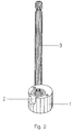
- FIG. 2 shows clamping body (1), holding head (2) and Bolt (3) assembled in perspective. In one axial direction it is Holding head now fixed because the cavity (4) of the Clamping body (1) is closed there in the other axial direction through the bolt (3), which in turn due to the azimuthal slot (5) of the Clamping body (1) fixed in its axial direction is.
- the clamping body (1) is in turn approximately cylindrical cavity of the element housed whose cylinder diameter is slightly larger than that of the clamping body (1).
- the rotation of the clamping body (1) is compensated the holding head (2) by an opposite Rotation around its axis of symmetry and transmits depending on the direction of rotation of the clamping body (1) pull or Compressive forces on the bolt (3). Are they in contact mutually standing surfaces of the element, the clamping body (1) and the holding head (2) not too smooth, so the clamping body (1) in each Rotational position due to frictional engagement with the element or the holding head (2) fixed.
Landscapes
- Engineering & Computer Science (AREA)
- General Engineering & Computer Science (AREA)
- Mechanical Engineering (AREA)
- Clamps And Clips (AREA)
- Coupling Device And Connection With Printed Circuit (AREA)
- Mechanical Coupling Of Light Guides (AREA)
- Handcart (AREA)
- Mutual Connection Of Rods And Tubes (AREA)
- Conductive Materials (AREA)
- Furniture Connections (AREA)
- Connection Of Plates (AREA)
Description
- Figur 1
- die Einzelteile der erfindungsgemäßen Verbindung, und
- Figur 2
- die Einzelteile zusammengesetzt.
Claims (16)
- Lösbare Verbindung bestehend aus zwei Elementen, und wenigstens einen dazwischen angeordneten Bolzen (3) der zumindest an einem Ende über einen an einem der Elemente angebrachten spannkörper (1) festgelegt ist, wobei der spannkörper (1) um eine im wesentlichen senkrecht zum Bolzen (3) verlaufende Achse gegenüber dem Element drehbar ist und der spannkörper (1) in jeder Drehposition gegenüber dem Bolzen (3) und/oder dem Element durch Kraftschluß festgelegt ist und die Festlegung des Bolzens (3) am Spannkörper (1) um eine von der Achse des Spann-Körpers (1) beabstandete, annähernd dazu parallele Achse drehbar ist, dadurch gekennzeichnet, daß die Verbindung zwischen Bolzen (3) und Spannkörper (1) durch einen lösbar am Bolzen (3) angebrachten Haltekopf (2) hergestellt ist, der relativ zum Spannkörper (1) drehbar ist.
- Verbindung nach Anspruch 1, dadurch, gekennzeichnet, daß der Bolzen (3) an seinem anderen Ende am anderen Element befestigt ist.
- Verbindung nach Anspruch 1, dadurch gekennzeichnet, daßder Bolzen (3) an seinem anderen Ende über einen weiteren, am anderen Element angebrachten Spannkörper festgelegt ist,der andere spannkörper um eine im wesentlichen senkrecht zum Bolzen verlaufenden Achse gegenüber dem anderen Element drehbar ist,die Befestigung des Bolzens (3) am anderen Spannkörper an einem von der Achse dieses Spannkörpers beabstandete, dazu annähernd parallele Achse drehbar ist sowieder andere Spannkörper in jeder Drehposition gegenüber dem Bolzen (3) und/oder dem anderen Element durch Kraftschluß festgelegt ist.
- Verbindung nach einem der vorhergehenden Ansprüche dadurch gekennzeichnet, daß der Kraftschluß ein Reibungsschluß ist.
- Verbindung nach einem der vorhergehenden Ansprüche dadurch gekennzeichnet, daß der Bolzen (3) zumindest eines der Elemente auf einer gawißen Länge. durchgreift.
- Verbindung nach einem der vorhergehenden Ansprüche, dadurch gekennzeichnet, daß der Bolzen (3) ein drittes Element, das zwischen den beiden Elementen angeordnet ist, durchstößt.
- Verbindung nach einem der vorhergehenden Ansprüche dadurch gekennzeichnet, daß der Spannkörper (1) in einem Hohlraum des Elementes untergebracht ist, der den Spannkörper (1) in Längsrichtung des Bolzens (3) beidseitig festlegt,
- Verbindung nach Anspruch 1, dadurch gekennzeichnet daß der Ealtekopf (2) auch mit dem Spannkörper (1) lösbar verbunden ist.
- Verbindung nach Anspruch 8 oder 1, dadurch gekennzeichnet, daß der Haltekopf (2) einen im wesentlichen in axialer Richtung des Spannkörpers (1) verlaufenden Schlitz (7) aufweist, dessen Flanken beidseits des Bolzens (3) in eine in azimutaler Richtung des Bolzens (3) verlaufende Nut (8) eingreifen.
- Verbindung nach Anspruch 9, dadurch gekennzeichnet, daß die azimutal verlaufende Nut (8) des Bolzens (3) eine umlaufende Ringnut ist.
- Verbindung nach einem der vorhergehenden Ansprüche, dadurch gekennzeichnet, daß der Bolzen (3) an seinem Ende und/oder der Haltekopf (2) in einem außeraxialen Hohlraum (4) des Spannkörpers (1) untergebracht und in Längsrichtung des Bolzens (3) festgelegt ist.
- Verbindung nach einem der vorhergehenden AnSprüche, dadurch gekennzeichnet, daß der Bolzen (3) einen azimutal verlaufenden Schlitz (5) des Spannkörpers (1) durchgreift.
- Verbindung nach Anspruch 12, dadurch gekennzeichnet, daß zwischen einer axialen Stirnseite des Spannkörpers (1) und dem azimutal verlaufenden schlitz (5) des Spannkörpers (1) ein im wesentlichen axialer Schlitz (6) verläuft, dessen Breite größer ist als der Durchmesser des Bolzens (3).
- , Verbindung nach einen der vorhergehenden Ansprüche, dadurch gekennzeichnet, daß ein Hohlraum des Elements und/oder des Spannkörpers (1) und/oder der spannkörper (1) selbst und/oder der Haltekopf (2) im wesentlichen zylindrisch geformt ist.
- Verbindung nach einem der vorhergehenden Ansprüche, dadurch gekennzeichnet, daß ein Hohlraum des Elementes und/oder des Spannkörpers (1) auf einer axialen Stirnseite offen ist.
- Verbindung nach einem der vorhergehenden Ansprüche, dadurch gekennzeichnet, daß ein Hohlraum des Elementes und/oder des Spannkörpers (1) auf einer axialen Stirnseite geschlossen ist.
Applications Claiming Priority (3)
| Application Number | Priority Date | Filing Date | Title |
|---|---|---|---|
| DE19857795A DE19857795A1 (de) | 1998-12-15 | 1998-12-15 | Lösbare Verbindung zweier Elemente |
| DE19857795 | 1998-12-15 | ||
| PCT/DE1999/003336 WO2000036308A1 (de) | 1998-12-15 | 1999-10-14 | Lösbare verbindung zweier elemente |
Publications (3)
| Publication Number | Publication Date |
|---|---|
| EP1144875A1 EP1144875A1 (de) | 2001-10-17 |
| EP1144875B1 true EP1144875B1 (de) | 2002-09-11 |
| EP1144875B2 EP1144875B2 (de) | 2007-11-21 |
Family
ID=7891130
Family Applications (1)
| Application Number | Title | Priority Date | Filing Date |
|---|---|---|---|
| EP99960789A Expired - Lifetime EP1144875B2 (de) | 1998-12-15 | 1999-10-14 | Lösbare verbindung zweier elemente |
Country Status (8)
| Country | Link |
|---|---|
| US (1) | US6863464B1 (de) |
| EP (1) | EP1144875B2 (de) |
| AT (1) | ATE224014T1 (de) |
| CA (1) | CA2355231C (de) |
| CZ (1) | CZ20012099A3 (de) |
| DE (3) | DE19857795A1 (de) |
| DK (1) | DK1144875T4 (de) |
| WO (1) | WO2000036308A1 (de) |
Families Citing this family (18)
| Publication number | Priority date | Publication date | Assignee | Title |
|---|---|---|---|---|
| US20050131394A1 (en) * | 2003-12-10 | 2005-06-16 | Minnesota Scientific, Inc. | Clamping device |
| US7604655B2 (en) | 2004-10-25 | 2009-10-20 | X-Spine Systems, Inc. | Bone fixation system and method for using the same |
| WO2006047711A2 (en) | 2004-10-25 | 2006-05-04 | Alphaspine, Inc. | Pedicle screw systems and methods |
| WO2006084997A1 (fr) * | 2005-02-11 | 2006-08-17 | Faurecia Interieur Industrie | Dispositif de fixation automatique d'une planche de bord sur une caisse de vehicule automobile |
| FR2890132B1 (fr) * | 2005-08-31 | 2007-11-16 | Faurecia Interieur Ind Snc | Dispositif perfectionne de fixation automatique d'une planche de bord sur une caisse de vehicule automobile. |
| DE102005015991B4 (de) * | 2005-04-07 | 2007-07-12 | Sprimag Spritzmaschinenbau Gmbh & Co Kg | Düse für Spritzapparate oder Spritzgeräte mit darin axial beweglicher Düsennadel |
| US7766946B2 (en) * | 2005-07-27 | 2010-08-03 | Frank Emile Bailly | Device for securing spinal rods |
| US7717943B2 (en) | 2005-07-29 | 2010-05-18 | X-Spine Systems, Inc. | Capless multiaxial screw and spinal fixation assembly and method |
| US7909830B2 (en) * | 2005-08-25 | 2011-03-22 | Synthes Usa, Llc | Methods of spinal fixation and instrumentation |
| DE102005043751A1 (de) * | 2005-09-13 | 2007-03-22 | Werkstückspanntechnik GmbH | Spanneinrichtung |
| WO2007041702A2 (en) | 2005-10-04 | 2007-04-12 | Alphaspine, Inc. | Pedicle screw system with provisional locking aspects |
| US20090199375A1 (en) | 2006-01-20 | 2009-08-13 | Fred Koelling | Latching system |
| WO2008119006A1 (en) * | 2007-03-27 | 2008-10-02 | Alpinespine Llc | Pedicle screw system configured to receive a straight or a curved rod |
| US20150147113A1 (en) * | 2013-11-26 | 2015-05-28 | II Phillip C. Crabtree | Frameless furniture system |
| DE102014011601A1 (de) | 2014-08-02 | 2016-02-04 | Daimler Ag | Befestigungsanordnung eines ersten Gehäuseelements eines Getriebes an einem zweiten Gehäuseelement eines Motors eines Kraftwagens |
| CN107084179A (zh) * | 2017-05-27 | 2017-08-22 | 苏州工业职业技术学院 | 卡扣式连接结构及连接方法 |
| USD911813S1 (en) * | 2018-02-23 | 2021-03-02 | Mcs Industries, Inc. | Cam lock |
| ES3004607A1 (es) * | 2023-09-08 | 2025-03-12 | Univ Del Pais Vasco / Euskal Herriko Unibertsitatea | Dispositivo de union para estructuras de madera |
Family Cites Families (11)
| Publication number | Priority date | Publication date | Assignee | Title |
|---|---|---|---|---|
| LU57387A1 (de) | 1968-11-25 | 1969-03-03 | ||
| US3851601A (en) * | 1973-02-09 | 1974-12-03 | J Davis | Display case stand |
| JPH0139921Y2 (de) * | 1984-11-07 | 1989-11-30 | ||
| US4783189A (en) † | 1987-05-20 | 1988-11-08 | Bugg Stuart E | Connectors for assembling structural members |
| NO882685L (no) * | 1988-06-17 | 1989-12-18 | Kirsten Birkeland | Innredningssystem. |
| ES2014639A6 (es) * | 1989-06-05 | 1990-07-16 | Pujol & Tarago | Dispositivo de enganche para cables metalicos. |
| US5403109A (en) * | 1993-06-09 | 1995-04-04 | Hon Industries Inc. | Fastening device for furniture construction and method of manufacture |
| US5590975A (en) * | 1994-12-06 | 1997-01-07 | Horntvedt; Earl | Fastening assembly |
| GB2301644B (en) * | 1995-05-31 | 1999-03-10 | Titus Int Plc | Joint forming devices |
| WO1997032140A2 (de) | 1996-02-28 | 1997-09-04 | Friedrich Stich | Verbindungselement für bauteile aus holz |
| US5810505A (en) * | 1996-07-26 | 1998-09-22 | Kimball International, Inc. | Double threaded fastener system |
-
1998
- 1998-12-15 DE DE19857795A patent/DE19857795A1/de not_active Withdrawn
-
1999
- 1999-10-14 US US09/868,159 patent/US6863464B1/en not_active Expired - Fee Related
- 1999-10-14 DE DE59902704T patent/DE59902704D1/de not_active Expired - Fee Related
- 1999-10-14 CA CA002355231A patent/CA2355231C/en not_active Expired - Fee Related
- 1999-10-14 DE DE19982716T patent/DE19982716D2/de not_active Ceased
- 1999-10-14 AT AT99960789T patent/ATE224014T1/de not_active IP Right Cessation
- 1999-10-14 DK DK99960789T patent/DK1144875T4/da active
- 1999-10-14 CZ CZ20012099A patent/CZ20012099A3/cs unknown
- 1999-10-14 EP EP99960789A patent/EP1144875B2/de not_active Expired - Lifetime
- 1999-10-14 WO PCT/DE1999/003336 patent/WO2000036308A1/de not_active Ceased
Also Published As
| Publication number | Publication date |
|---|---|
| WO2000036308A1 (de) | 2000-06-22 |
| DE19982716D2 (de) | 2002-07-11 |
| DE19857795A1 (de) | 2000-06-29 |
| EP1144875A1 (de) | 2001-10-17 |
| EP1144875B2 (de) | 2007-11-21 |
| ATE224014T1 (de) | 2002-09-15 |
| DK1144875T3 (da) | 2003-01-20 |
| CA2355231C (en) | 2009-01-06 |
| DE59902704D1 (de) | 2002-10-17 |
| DK1144875T4 (da) | 2008-04-07 |
| CA2355231A1 (en) | 2000-06-22 |
| US6863464B1 (en) | 2005-03-08 |
| CZ20012099A3 (cs) | 2001-12-12 |
Similar Documents
| Publication | Publication Date | Title |
|---|---|---|
| EP1144875B1 (de) | Lösbare verbindung zweier elemente | |
| DE102013209371B4 (de) | Kupplungsteil, insbesondere Schneidkopf für ein Rotationswerkzeug sowie hierzu komplementäres Kupplungsteil und Rotationswerkzeug | |
| EP1477690B1 (de) | Kugelgelenkverbindung | |
| EP0792628B1 (de) | Endoprothese für ein künstliches Hüftgelenk | |
| DE102015003439B3 (de) | Tür- oder Fensterscharnier | |
| EP2755786A1 (de) | Spannsystem sowie grundkörper, spannzange und rotationswerkzeug dafür und ein installationsverfahren für das rotationswerkzeug im spannsystem | |
| EP4013969B1 (de) | Anzugelement | |
| DE4030978C2 (de) | Verbindungseinrichtung für Rohre | |
| EP2379260B1 (de) | Werkzeug für die spanende bearbeitung, insbesondere langdrehwerkzeug | |
| EP0267161B1 (de) | Schraubvorrichtung | |
| EP0238921B1 (de) | In den Umlaufträger eines Planetengetriebes einsetzbarer Planetenradbolzen | |
| EP0269666B1 (de) | Verbindungseinrichtung | |
| EP0267200A1 (de) | Beschlag zum lösbaren verbinden von zwei bauteilen. | |
| AT506192B1 (de) | Verbindungselement | |
| EP0760890B1 (de) | Mehrteiliges scharnier | |
| DE8712119U1 (de) | Knotenelement zur Verbindung von Stabelementen | |
| DE19604665A1 (de) | Querverbinder für Profilstäbe | |
| DE19532456C2 (de) | Verbinder für Holzteile | |
| DE3205088A1 (de) | Mitnehmerkupplung fuer werkzeuge | |
| DE20003929U1 (de) | Befestigungskörper für einen Tür- und/oder Fensterbeschlag | |
| DE29917551U1 (de) | Scharnier mit zwei relativ zueinander um eine gemeinsame Drehachse verdrehbaren Scharnierteilen | |
| DE10210627C1 (de) | Vorrichtung zum Verbinden wenigstens zweier Bauteile | |
| DE29912708U1 (de) | Schraubwerkzeug zum Eindrehen von Gewindebolzen | |
| DE2617554B2 (de) | Verbindung für Blechrohre, insbesondere für den Brunnenbau und für Pfahlgründungen | |
| EP0491154A1 (de) | Bohrer |
Legal Events
| Date | Code | Title | Description |
|---|---|---|---|
| PUAI | Public reference made under article 153(3) epc to a published international application that has entered the european phase |
Free format text: ORIGINAL CODE: 0009012 |
|
| 17P | Request for examination filed |
Effective date: 20010716 |
|
| AK | Designated contracting states |
Kind code of ref document: A1 Designated state(s): AT BE CH CY DE DK ES FI FR GB GR IE IT LI LU MC NL PT SE |
|
| AX | Request for extension of the european patent |
Free format text: LT;LV;SI PAYMENT 20010716 |
|
| GRAG | Despatch of communication of intention to grant |
Free format text: ORIGINAL CODE: EPIDOS AGRA |
|
| GRAG | Despatch of communication of intention to grant |
Free format text: ORIGINAL CODE: EPIDOS AGRA |
|
| GRAH | Despatch of communication of intention to grant a patent |
Free format text: ORIGINAL CODE: EPIDOS IGRA |
|
| 17Q | First examination report despatched |
Effective date: 20020314 |
|
| GRAH | Despatch of communication of intention to grant a patent |
Free format text: ORIGINAL CODE: EPIDOS IGRA |
|
| GRAA | (expected) grant |
Free format text: ORIGINAL CODE: 0009210 |
|
| AK | Designated contracting states |
Kind code of ref document: B1 Designated state(s): AT BE CH CY DE DK ES FI FR GB GR IE IT LI LU MC NL PT SE |
|
| AX | Request for extension of the european patent |
Free format text: SI PAYMENT 20010716 |
|
| PG25 | Lapsed in a contracting state [announced via postgrant information from national office to epo] |
Ref country code: GR Free format text: LAPSE BECAUSE OF FAILURE TO SUBMIT A TRANSLATION OF THE DESCRIPTION OR TO PAY THE FEE WITHIN THE PRESCRIBED TIME-LIMIT Effective date: 20020911 |
|
| REF | Corresponds to: |
Ref document number: 224014 Country of ref document: AT Date of ref document: 20020915 Kind code of ref document: T |
|
| REG | Reference to a national code |
Ref country code: GB Ref legal event code: FG4D Free format text: NOT ENGLISH |
|
| REG | Reference to a national code |
Ref country code: CH Ref legal event code: EP |
|
| PG25 | Lapsed in a contracting state [announced via postgrant information from national office to epo] |
Ref country code: IE Free format text: LAPSE BECAUSE OF NON-PAYMENT OF DUE FEES Effective date: 20021014 |
|
| REG | Reference to a national code |
Ref country code: IE Ref legal event code: FG4D Free format text: GERMAN |
|
| REF | Corresponds to: |
Ref document number: 59902704 Country of ref document: DE Date of ref document: 20021017 |
|
| PG25 | Lapsed in a contracting state [announced via postgrant information from national office to epo] |
Ref country code: CY Free format text: LAPSE BECAUSE OF FAILURE TO SUBMIT A TRANSLATION OF THE DESCRIPTION OR TO PAY THE FEE WITHIN THE PRESCRIBED TIME-LIMIT Effective date: 20021031 |
|
| GBT | Gb: translation of ep patent filed (gb section 77(6)(a)/1977) |
Effective date: 20021209 |
|
| REG | Reference to a national code |
Ref country code: DK Ref legal event code: T3 |
|
| PG25 | Lapsed in a contracting state [announced via postgrant information from national office to epo] |
Ref country code: PT Free format text: LAPSE BECAUSE OF FAILURE TO SUBMIT A TRANSLATION OF THE DESCRIPTION OR TO PAY THE FEE WITHIN THE PRESCRIBED TIME-LIMIT Effective date: 20030124 |
|
| ET | Fr: translation filed | ||
| PG25 | Lapsed in a contracting state [announced via postgrant information from national office to epo] |
Ref country code: ES Free format text: LAPSE BECAUSE OF FAILURE TO SUBMIT A TRANSLATION OF THE DESCRIPTION OR TO PAY THE FEE WITHIN THE PRESCRIBED TIME-LIMIT Effective date: 20030328 |
|
| PG25 | Lapsed in a contracting state [announced via postgrant information from national office to epo] |
Ref country code: MC Free format text: LAPSE BECAUSE OF NON-PAYMENT OF DUE FEES Effective date: 20030501 |
|
| PLBQ | Unpublished change to opponent data |
Free format text: ORIGINAL CODE: EPIDOS OPPO |
|
| PLBI | Opposition filed |
Free format text: ORIGINAL CODE: 0009260 |
|
| PLAX | Notice of opposition and request to file observation + time limit sent |
Free format text: ORIGINAL CODE: EPIDOSNOBS2 |
|
| 26 | Opposition filed |
Opponent name: HETTICH-HEINZE GMBH & CO.KG Effective date: 20030610 |
|
| REG | Reference to a national code |
Ref country code: IE Ref legal event code: MM4A |
|
| NLR1 | Nl: opposition has been filed with the epo |
Opponent name: HETTICH-HEINZE GMBH & CO.KG |
|
| PLAX | Notice of opposition and request to file observation + time limit sent |
Free format text: ORIGINAL CODE: EPIDOSNOBS2 |
|
| PLBB | Reply of patent proprietor to notice(s) of opposition received |
Free format text: ORIGINAL CODE: EPIDOSNOBS3 |
|
| PLAY | Examination report in opposition despatched + time limit |
Free format text: ORIGINAL CODE: EPIDOSNORE2 |
|
| PLBC | Reply to examination report in opposition received |
Free format text: ORIGINAL CODE: EPIDOSNORE3 |
|
| PUAH | Patent maintained in amended form |
Free format text: ORIGINAL CODE: 0009272 |
|
| STAA | Information on the status of an ep patent application or granted ep patent |
Free format text: STATUS: PATENT MAINTAINED AS AMENDED |
|
| 27A | Patent maintained in amended form |
Effective date: 20071121 |
|
| AK | Designated contracting states |
Kind code of ref document: B2 Designated state(s): AT BE CH CY DE DK ES FI FR GB GR IE IT LI LU MC NL PT SE |
|
| AX | Request for extension of the european patent |
Extension state: SI |
|
| REG | Reference to a national code |
Ref country code: CH Ref legal event code: AEN Free format text: AUFRECHTERHALTUNG DES PATENTES IN GEAENDERTER FORM |
|
| NLR2 | Nl: decision of opposition |
Effective date: 20071121 |
|
| REG | Reference to a national code |
Ref country code: ES Ref legal event code: FD2A Effective date: 20021015 |
|
| PGFP | Annual fee paid to national office [announced via postgrant information from national office to epo] |
Ref country code: FI Payment date: 20071019 Year of fee payment: 9 |
|
| GBTA | Gb: translation of amended ep patent filed (gb section 77(6)(b)/1977) | ||
| PGFP | Annual fee paid to national office [announced via postgrant information from national office to epo] |
Ref country code: SE Payment date: 20071023 Year of fee payment: 9 Ref country code: BE Payment date: 20071022 Year of fee payment: 9 |
|
| REG | Reference to a national code |
Ref country code: DK Ref legal event code: T4 |
|
| NLR3 | Nl: receipt of modified translations in the netherlands language after an opposition procedure | ||
| ET3 | Fr: translation filed ** decision concerning opposition | ||
| PGFP | Annual fee paid to national office [announced via postgrant information from national office to epo] |
Ref country code: NL Payment date: 20081023 Year of fee payment: 10 |
|
| PGFP | Annual fee paid to national office [announced via postgrant information from national office to epo] |
Ref country code: LU Payment date: 20081027 Year of fee payment: 10 Ref country code: DK Payment date: 20081024 Year of fee payment: 10 Ref country code: DE Payment date: 20081013 Year of fee payment: 10 Ref country code: CH Payment date: 20081027 Year of fee payment: 10 |
|
| PGFP | Annual fee paid to national office [announced via postgrant information from national office to epo] |
Ref country code: AT Payment date: 20081023 Year of fee payment: 10 |
|
| PGFP | Annual fee paid to national office [announced via postgrant information from national office to epo] |
Ref country code: IT Payment date: 20081028 Year of fee payment: 10 |
|
| BERE | Be: lapsed |
Owner name: *NIKLAUS HILMAR Effective date: 20081031 |
|
| PGFP | Annual fee paid to national office [announced via postgrant information from national office to epo] |
Ref country code: FR Payment date: 20081021 Year of fee payment: 10 |
|
| PGFP | Annual fee paid to national office [announced via postgrant information from national office to epo] |
Ref country code: GB Payment date: 20081024 Year of fee payment: 10 |
|
| PG25 | Lapsed in a contracting state [announced via postgrant information from national office to epo] |
Ref country code: BE Free format text: LAPSE BECAUSE OF NON-PAYMENT OF DUE FEES Effective date: 20081031 |
|
| PG25 | Lapsed in a contracting state [announced via postgrant information from national office to epo] |
Ref country code: FI Free format text: LAPSE BECAUSE OF FAILURE TO SUBMIT A TRANSLATION OF THE DESCRIPTION OR TO PAY THE FEE WITHIN THE PRESCRIBED TIME-LIMIT Effective date: 20071121 |
|
| REG | Reference to a national code |
Ref country code: NL Ref legal event code: V1 Effective date: 20100501 |
|
| REG | Reference to a national code |
Ref country code: CH Ref legal event code: PL |
|
| REG | Reference to a national code |
Ref country code: DK Ref legal event code: EBP |
|
| REG | Reference to a national code |
Ref country code: FR Ref legal event code: ST Effective date: 20100630 |
|
| PG25 | Lapsed in a contracting state [announced via postgrant information from national office to epo] |
Ref country code: NL Free format text: LAPSE BECAUSE OF NON-PAYMENT OF DUE FEES Effective date: 20100501 Ref country code: FR Free format text: LAPSE BECAUSE OF NON-PAYMENT OF DUE FEES Effective date: 20091102 Ref country code: DE Free format text: LAPSE BECAUSE OF NON-PAYMENT OF DUE FEES Effective date: 20100501 |
|
| PG25 | Lapsed in a contracting state [announced via postgrant information from national office to epo] |
Ref country code: AT Free format text: LAPSE BECAUSE OF NON-PAYMENT OF DUE FEES Effective date: 20091014 |
|
| PG25 | Lapsed in a contracting state [announced via postgrant information from national office to epo] |
Ref country code: LI Free format text: LAPSE BECAUSE OF NON-PAYMENT OF DUE FEES Effective date: 20091031 Ref country code: CH Free format text: LAPSE BECAUSE OF NON-PAYMENT OF DUE FEES Effective date: 20091031 |
|
| PG25 | Lapsed in a contracting state [announced via postgrant information from national office to epo] |
Ref country code: GB Free format text: LAPSE BECAUSE OF NON-PAYMENT OF DUE FEES Effective date: 20091014 |
|
| PG25 | Lapsed in a contracting state [announced via postgrant information from national office to epo] |
Ref country code: SE Free format text: LAPSE BECAUSE OF NON-PAYMENT OF DUE FEES Effective date: 20080327 |
|
| PG25 | Lapsed in a contracting state [announced via postgrant information from national office to epo] |
Ref country code: DK Free format text: LAPSE BECAUSE OF NON-PAYMENT OF DUE FEES Effective date: 20091031 |
|
| PG25 | Lapsed in a contracting state [announced via postgrant information from national office to epo] |
Ref country code: IT Free format text: LAPSE BECAUSE OF NON-PAYMENT OF DUE FEES Effective date: 20091014 |
|
| PG25 | Lapsed in a contracting state [announced via postgrant information from national office to epo] |
Ref country code: LU Free format text: LAPSE BECAUSE OF NON-PAYMENT OF DUE FEES Effective date: 20091014 |