EP1144948B1 - Capteur gyroscopique et appareil de mesure de rotation - Google Patents
Capteur gyroscopique et appareil de mesure de rotation Download PDFInfo
- Publication number
- EP1144948B1 EP1144948B1 EP00920829A EP00920829A EP1144948B1 EP 1144948 B1 EP1144948 B1 EP 1144948B1 EP 00920829 A EP00920829 A EP 00920829A EP 00920829 A EP00920829 A EP 00920829A EP 1144948 B1 EP1144948 B1 EP 1144948B1
- Authority
- EP
- European Patent Office
- Prior art keywords
- resonator
- electrodes
- sensor according
- axis
- transducers
- Prior art date
- Legal status (The legal status is an assumption and is not a legal conclusion. Google has not performed a legal analysis and makes no representation as to the accuracy of the status listed.)
- Expired - Lifetime
Links
Images

Classifications
-
- G—PHYSICS
- G01—MEASURING; TESTING
- G01C—MEASURING DISTANCES, LEVELS OR BEARINGS; SURVEYING; NAVIGATION; GYROSCOPIC INSTRUMENTS; PHOTOGRAMMETRY OR VIDEOGRAMMETRY
- G01C19/00—Gyroscopes; Turn-sensitive devices using vibrating masses; Turn-sensitive devices without moving masses; Measuring angular rate using gyroscopic effects
- G01C19/56—Turn-sensitive devices using vibrating masses, e.g. vibratory angular rate sensors based on Coriolis forces
-
- G—PHYSICS
- G01—MEASURING; TESTING
- G01C—MEASURING DISTANCES, LEVELS OR BEARINGS; SURVEYING; NAVIGATION; GYROSCOPIC INSTRUMENTS; PHOTOGRAMMETRY OR VIDEOGRAMMETRY
- G01C19/00—Gyroscopes; Turn-sensitive devices using vibrating masses; Turn-sensitive devices without moving masses; Measuring angular rate using gyroscopic effects
- G01C19/56—Turn-sensitive devices using vibrating masses, e.g. vibratory angular rate sensors based on Coriolis forces
- G01C19/567—Turn-sensitive devices using vibrating masses, e.g. vibratory angular rate sensors based on Coriolis forces using the phase shift of a vibration node or antinode
- G01C19/5691—Turn-sensitive devices using vibrating masses, e.g. vibratory angular rate sensors based on Coriolis forces using the phase shift of a vibration node or antinode of essentially three-dimensional [3D] vibrators, e.g. wine glass-type vibrators
Definitions
- the present invention relates generally to the gyroscopic sensors having a mechanical element, called resonator, able to vibrate on a mechanical resonance, detectors sensitive to an elongation given by the resonator vibration and application transducers of forces to the resonator and more particularly the gyro sensors including the resonator, in the form of bell or crown of revolution, is attached along its axis and has a circular edge in a plane perpendicular to the axis, away from the point of attachment in the axial direction.
- the resonator is constituted by a hemispherical silica cap, which makes it possible to obtain very high quality factors. , exceeding 5.10 6 .
- the sensors capacitive in nature, are placed so that the elongation of the vibration of the resonator in the radial direction changes the inter-electrode distance.
- the transducers for exciting the resonance are placed to exert electrostatic forces at least in two particular radial directions where the elongation is detected by varying the inter-electrode distance.
- detector gaps and transducers must be weak.
- the present invention aims to provide a sensor Gyroscopic of the kind defined above, feasible at a cost much lower than those that exist to date.
- the invention makes use of a neglected finding so far, namely that the edge of a resonator in the shape of a bell or a cap, excited in a vibration mode causing a deformation with radial and tangential components, also presents a displacement component parallel to the axis of the resonator.
- a resonator hemispherical we will see that the amplitude of the axial displacement is equal to half the amplitude of the radial displacement.
- these means include detectors and transducers that can placed on the substrate, which is orthogonal to the axis, in face of the conductive edge of the resonator.
- Detectors and / or transducers may have various constitutions known. They may include electrodes cooperating with the resonator to form capacitive sensors and electrodes cooperating with the resonator to constitute capacitive transducers excitation.
- the detection and excitation means can be constituted by the same components, working in time shared or using carrier modulation at different frequencies. Detection of movements in presence of the excitation signal can then be effected by synchronous detection. Moreover, the detectors and / or Transducers may be of a nature other than electrostatic.
- the bottom of the resonator is advantageously fixed on the substrate by means of a material having substantially same coefficient of expansion as the resonator, so make the sensor very insensitive to variations in temperature.
- the senor according to the invention uses the axial component of the displacement of the edge of the resonator for detect the amplitude of the vibration at the measuring points and also to excite the latter.
- the amplitude of the axial displacement of the edge is no longer necessarily equal to half of the radial amplitude.
- the amplitude of the axial deformations of the edge decreases when the depth (axial length) of the resonator increases from the hemispherical form.
- the resonator may have a wall thickness constant. It can also be thicker close to the edge, so as to increase the effective surface of the electrodes carried by the substrate.
- the electrodes placed on the substrate will present advantageously a radial dimension greater than that of edge of the resonator, so that they overflow each side and that a slight decentering has no effect on the measured.
- u, v and w denote the amplitude of the axial displacement, tangential displacement and radial displacement.
- ⁇ denotes the azimuth.
- Figure 2 shows, respectively in solid lines and in mixed lines, successive forms taken by the resonator in vibration and shows the existence of a axial elongation half of the radial elongation.
- the invention proposes to use the axial displacement u.
- the amplitude of this displacement is equal, in the case of a hemispherical resonator, to the half of the amplitude of the radial displacement w, which seems at first sight a defect.
- the gap inter-electrode distance
- the gap can be defined precisely, for example using shims, during assembly of the resonator on a substrate.
- the efficiency of the transducers and detectors is in first approximation proportional at the surface of the electrodes divided by the square of the air gap. So we see the value of the proposed solution, which allows to significantly reduce the air gap.
- the value of the air gap intervenes by its square the decrease of the air gap makes it possible to compensate, and beyond, the most low active area of the electrodes.
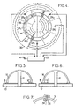
- the sensor shown in FIG. substrate 10 which is fixed by a rod 12, the resonator 14. So that the size of the gap varies little in temperature, it is better to build the support rod 12 of the same material as the resonator or a material having a coefficient of thermal expansion nearby.
- the silica resonator can be formed, which allows to obtain high overvoltage coefficients, with a conductive metal coating.
- This coating metal may be limited to a ring covering the edge of the resonator and to metallized tracks reference potential, which can be a constant potential (usually mass) or an adjustable potential.
- reference potential can be a constant potential (usually mass) or an adjustable potential.
- the rod 12 when is made of the same material as the resonator, can be in one piece with the latter and be embedded in the substrate 10.
- the substrate can consist of a part metal coated with an insulating film on which the fixed electrodes of the transducers and detectors whose thickness is schematized in 16 on the figure 3.
- Electrodes in Generally speaking, at least two electrodes (or two pairs of opposing electrodes) in orientations that are mutually orthogonal in a mode repository chosen, that is to say at 45 ° from each other in the case of order 2. Similarly, we will place the transducers applying forces in two directions mutually orthogonal in this same reference system.
- the electrostatic transducers are defined by two pairs of electrodes 24 1 and 24 2 aligned in two directions at 45 ° to one another, making it possible to maintain a vibration of order 2.
- the detectors are defined by two pairs of electrodes 26 1 and 26 2 , also arranged in two directions at 45 ° to each other.
- the output signals taken from the electrodes 26 1 and 26 2 are applied to an electronic computing and power circuit 22 which supplies the transducers to maintain a constant amplitude of vibration and provides an output signal which, depending on the case, will be representative an angle of rotation or a speed.
- the electrodes 24 and 26 In order to tolerate centering errors of the resonator with respect to the substrate and avoid any influence of the radial component of vibration on the signal of output, the electrodes 24 and 26 have a radial width greater than the thickness of the edge of the resonator 40, schematized at 28 in FIG.
- the electronic measuring and control circuit 22 can have very varied constitutions. It can in particular have the constitution described in EP-A-0 810 418 to form a gyrometer. he is also possible to use one of the circuit constitutions described in document EP 0 578 519 making it possible to obtain gyrometer operation (speed measurement of rotation) or gyroscope (angle of rotation measurement).
- the mechanical characteristics of the resonator so that it has a natural frequency between 3 kHz and 10 kHz, because the performance decreases beyond this last value.
- a hemispherical resonator having a diameter of between 10 and 50 mm gave good results.
- the amplitude of the vibration can be regulated so as to be in the range of 0.5 to 1 ⁇ m.
- the resonator may be grounded through its support 12. However, in other cases it may be preferable to carry the resonator to a different, fixed or modulated potential.
- the resonator will be contained in a housing (not shown) in which there is a reduced pressure, in practice less than 10 -3 millibar, so as to reduce the gas damping.
- the resonator can have a shape other than hemispherical.
- resonator section along a plane passing through the axis can be in the shape of a parabola or a section ellipse.
- Figure 5 shows a resonator on which this result is achieved by giving the inner surface of the resonator a cylindrical shape, over a small length h relative to the total depth of the resonator.
- this result is achieved by giving the. inner surface and on the outer surface a shape that deviates from a spherical surface in a zone h also low compared to the depth of the resonator.
- the transducers and / or detectors can have a different constitution of the one shown in Figure 4.
- Figure 7 shows for example a sensor consisting of two electrodes placed on the substrate 10.
- the central electrode 34 is strip-shaped radial.
- the other electrode 36 is U-shaped whose branches surround the central electrode 34.
- the constitution of the resonator is simplified because it does not need to be coated with a conductive layer.
- the capacity of the capacitor constituted by the electrodes 34 and 36 varies during axial vibrations, because the constant dielectric material constituting the resonator (silica for example) is different from that of the atmosphere, generally at very low pressure, between the edge of the resonator and the electrodes.
- the electrodes 34 and 36 must have a sufficient radial extent for a slight decentering of the resonator has no effect on the measurement despite the radial component of the vibration of the resonator.
Landscapes
- Physics & Mathematics (AREA)
- Engineering & Computer Science (AREA)
- General Physics & Mathematics (AREA)
- Radar, Positioning & Navigation (AREA)
- Remote Sensing (AREA)
- Gyroscopes (AREA)
Description
- un résonateur en forme de cloche ou de calotte de révolution, fixé suivant son axe et présentant un bord circulaire situé dans un plan perpendiculaire à l'axe, à distance du point de fixation du résonateur dans le sens axial,
- et un substrat portant des moyens de détection et d'excitation coopérant avec le résonateur.
- la figure 1 représente schématiquement un résonateur hémisphérique et indique les paramètres qui interviennent dans la vibration.
- la figure 2 montre des formes extrêmes prises lors des vibrations d'ordre 2 d'un résonateur du genre montré en figure 1, les déformations étant très exagérées pour plus de clarté ;
- la figure 2A montre, suivant un plan à 45° de celui de la figure 2, une forme extrême que peut prendre le résonateur ;
- la figure 3 montre un mode de montage possible d'un résonateur sur un substrat ;
- la figure 4 est un schéma en plan montrant une disposition possible des électrodes, des transducteurs et des détecteurs sur le substrat ;
- les figures 5 et 6 sont des schémas montrant des variantes de réalisation du résonateur ; et
- la figure 7 montre schématiquement, en plan, un jeu d'électrodes de condensateur utilisable comme détecteur, à la place des électrodes de la figure 4.
Claims (10)
- Capteur gyroscopique comprenant :caractérisé en ce que les moyens de détection et d'excitation coopèrent avec une composante axiale d'une vibration du résonateur.un résonateur (14) en forme de cloche ou de calotte de révolution, fixé suivant son axe et présentant un bord circulaire situé dans un plan perpendiculaire à l'axe, à distance du point de fixation du résonateur dans le sens axial,et un substrat (10) portant des moyens de détection et d'excitation coopérant avec le résonateur,
- Capteur selon la revendication 1, caractérisé en ce que les dits moyens de détection et d'excitation comprennent des détecteurs et transducteurs (241, 242, 261, 262) placés sur le substrat, qui est plan et orthogonal à l'axe, en face du bord conducteur du résonateur.
- Capteur selon la revendication 2, caractérisé en ce que les détecteurs et transducteurs comprennent respectivement des électrodes (261,262) coopérant avec le résonateur pour constituer des détecteurs capacitifs et des électrodes (241,242) coopérant avec le résonateur pour constituer des transducteurs capacitifs d'excitation.
- Capteur selon la revendication 3, caractérisé en ce que la distance au repos entre les électrodes et le bord du résonateur est comprise entre 5 µm et 100 µm.
- Capteur selon la revendication 3 ou 4, caractérisé en ce que les électrodes débordent radialement de part et d'autre du bord du résonateur.
- Capteur selon l'une quelconque des revendications 3 à 5, destiné à vibrer en mode d'ordre 2, ayant au moins deux jeux d'électrodes de détection (261,262) alignés suivant deux directions à 45° et deux jeux d'électrodes (241,242) de transducteurs alignés suivant deux directions à 45° l'une de l'autre.
- Capteur suivant l'une quelconque des revendications 3 à 5, caractérisé en ce que le résonateur est constitué en métal ou en silice métallisée.
- Capteur selon l'une quelconque des revendications 1 à 7, caractérisé en ce que le résonateur est fixé au substrat par des moyens constitués d'un matériau ayant sensiblement le même coefficient de dilatation que le résonateur.
- Capteur selon l'une quelconque des revendications 1 à 8, caractérisé en ce que le résonateur est maintenu à un potentiel défini, fixe ou modulé, par l'intermédiaire des moyens de fixation suivant son axe.
- Appareil de mesure de rotation comprenant un capteur selon l'une quelconque des revendications 3 à 5, et un circuit électronique (22) recevant le signal de sortie fourni par les électrodes des détecteurs et alimentant les électrodes de transducteurs pour entretenir la vibration en créant des forces à la fréquence de résonance du résonateur et des moyens de calcul de la rotation du résonateur autour de son axe à partir d'un traitement des signaux.
Applications Claiming Priority (3)
| Application Number | Priority Date | Filing Date | Title |
|---|---|---|---|
| FR9905204A FR2792722B1 (fr) | 1999-04-23 | 1999-04-23 | Capteur gyroscopique et appareil de mesure de rotation en comportant application |
| FR9905204 | 1999-04-23 | ||
| PCT/FR2000/001005 WO2000065307A2 (fr) | 1999-04-23 | 2000-04-18 | Capteur gyroscopique et appareil de mesure de rotation |
Publications (3)
| Publication Number | Publication Date |
|---|---|
| EP1144948A2 EP1144948A2 (fr) | 2001-10-17 |
| EP1144948A3 EP1144948A3 (fr) | 2002-09-11 |
| EP1144948B1 true EP1144948B1 (fr) | 2005-02-16 |
Family
ID=9544813
Family Applications (1)
| Application Number | Title | Priority Date | Filing Date |
|---|---|---|---|
| EP00920829A Expired - Lifetime EP1144948B1 (fr) | 1999-04-23 | 2000-04-18 | Capteur gyroscopique et appareil de mesure de rotation |
Country Status (11)
| Country | Link |
|---|---|
| US (1) | US6474161B1 (fr) |
| EP (1) | EP1144948B1 (fr) |
| JP (1) | JP4663128B2 (fr) |
| KR (1) | KR100731320B1 (fr) |
| CA (1) | CA2335763C (fr) |
| DE (1) | DE60018165T2 (fr) |
| FR (1) | FR2792722B1 (fr) |
| RU (1) | RU2193753C2 (fr) |
| TW (1) | TW575726B (fr) |
| WO (1) | WO2000065307A2 (fr) |
| ZA (1) | ZA200007492B (fr) |
Families Citing this family (27)
| Publication number | Priority date | Publication date | Assignee | Title |
|---|---|---|---|---|
| RU2194947C1 (ru) * | 2001-10-18 | 2002-12-20 | Федеральное государственное унитарное предприятие "Ижевский электромеханический завод "Купол" | Способ считывания и управления твердотельного волнового гироскопа с оптическими датчиками колебаний резонатора и устройство для его осуществления |
| FR2851040B1 (fr) | 2003-02-06 | 2005-03-18 | Sagem | Resonateur hemispherique a electrode de garde divisee |
| FR2857445B1 (fr) * | 2003-07-10 | 2005-09-02 | Sagem | Resonateur, notamment pour gyroscope vibrant |
| FR2859017B1 (fr) * | 2003-08-19 | 2005-09-30 | Sagem | Capteur de rotation inertiel a element sensible monte directement sur le corps |
| US7464590B1 (en) * | 2004-03-12 | 2008-12-16 | Thomson Licensing | Digitally programmable bandwidth for vibratory rate gyroscope |
| FR2925668B1 (fr) * | 2007-12-19 | 2010-01-15 | Sagem Defense Securite | Procede de correction de gain d'un organe capacitif et dispositif de mise en oeuvre |
| WO2009109969A2 (fr) * | 2008-03-03 | 2009-09-11 | Ramot At Tel-Aviv University Ltd. | Capteurs de vitesse mécaniques à micro-échelle |
| FR2945342B1 (fr) * | 2009-05-07 | 2011-05-20 | Sagem Defense Securite | Capteur vibrant a deux voies activees en sequence |
| FR2952426B1 (fr) * | 2009-11-12 | 2012-10-05 | Sagem Defense Securite | Resonateur a couche metallisee partielle |
| US8631702B2 (en) * | 2010-05-30 | 2014-01-21 | Honeywell International Inc. | Hemitoroidal resonator gyroscope |
| RU2521783C2 (ru) * | 2012-01-13 | 2014-07-10 | Открытое акционерное общество "Арзамасский приборостроительный завод имени П.И. Пландина" - ОАО "АПЗ" | Чувствительный элемент твердотельного волнового гироскопа (варианты) |
| CN104215235B (zh) * | 2013-06-05 | 2017-08-22 | 北京信息科技大学 | 一种新型钟形振子式角速率陀螺 |
| CN104296737B (zh) * | 2014-09-29 | 2018-06-05 | 北京理工大学 | 一种三维多曲面融合敏感结构微纳振幅电容检测系统 |
| CN104390638B (zh) * | 2014-12-01 | 2018-05-08 | 北京信息科技大学 | 一种三维多曲面融合敏感结构元件及包含该元件的振动陀螺 |
| US10119820B2 (en) | 2015-02-10 | 2018-11-06 | Northrop Grumman Systems Corporation | Wide rim vibratory resonant sensors |
| US10532943B2 (en) * | 2016-02-29 | 2020-01-14 | The Regents Of The University Of Michigan | Gyroscope and fabrication process |
| RU2659097C2 (ru) * | 2016-06-22 | 2018-06-28 | Валентин Владимирович Коваленко | Способ компенсации погрешности от углового ускорения основания для кориолисова вибрационного гироскопа с непрерывным съёмом навигационной информации |
| EP3336485B1 (fr) | 2016-12-15 | 2020-09-23 | Safran Landing Systems UK Limited | Composant aéronautique comprenant un capteur de braquage |
| CN107014366B (zh) * | 2017-03-30 | 2019-06-14 | 中国人民解放军国防科学技术大学 | 一种基于静电激励与检测的圆柱壳体振动陀螺 |
| CN108731660A (zh) * | 2018-03-28 | 2018-11-02 | 东南大学 | 一种基于pcb平面电极的半球谐振陀螺仪及其加工组装方法 |
| CN117203490A (zh) | 2021-04-23 | 2023-12-08 | 东京计器株式会社 | 曲面支撑结构体的制造方法及半球谐振陀螺仪 |
| CN114105075B (zh) * | 2021-11-12 | 2025-07-15 | 中国电子科技集团公司第二十六研究所 | 一种曲面电极的微半球陀螺结构及其制备方法 |
| CN114562989B (zh) * | 2021-12-09 | 2023-06-02 | 华中光电技术研究所(中国船舶重工集团公司第七一七研究所) | 一种基于光胶连接方式的半球谐振陀螺 |
| JP7729246B2 (ja) * | 2022-04-12 | 2025-08-26 | 株式会社デンソー | 微小振動体の実装構造 |
| WO2024005471A1 (fr) * | 2022-06-30 | 2024-01-04 | 대한민국(방위사업청장) | Coque de résonateur en bain d'oiseau et son procédé de fabrication |
| WO2024077035A1 (fr) | 2022-10-04 | 2024-04-11 | Enertia Microsystems Inc. | Gyroscopes vibratoires avec accessoires de résonateur |
| CN117589141B (zh) * | 2024-01-18 | 2024-03-19 | 四川图林科技有限责任公司 | 一种二件套半球谐振陀螺基座及其加工方法 |
Family Cites Families (14)
| Publication number | Priority date | Publication date | Assignee | Title |
|---|---|---|---|---|
| US3625067A (en) * | 1969-07-18 | 1971-12-07 | Gen Motors Corp | Device for detecting rotation about an axis and method of using the same |
| US4157041A (en) * | 1978-05-22 | 1979-06-05 | General Motors Corporation | Sonic vibrating bell gyro |
| US4951508A (en) * | 1983-10-31 | 1990-08-28 | General Motors Corporation | Vibratory rotation sensor |
| CA1250458A (fr) * | 1983-10-31 | 1989-02-28 | Edward J. Loper, Jr. | Gyroscope a resonateur hemispherique |
| EP0175508B1 (fr) * | 1984-09-07 | 1988-10-12 | The Marconi Company Limited | Gyroscope à rotor vibrant |
| FR2684759B1 (fr) * | 1991-12-05 | 1994-03-11 | Applications Gles Electr Meca | Cyrometre vibrant piezo-electrique. |
| US5329815A (en) * | 1991-12-19 | 1994-07-19 | Motorola, Inc. | Vibration monolithic gyroscope |
| RU2056038C1 (ru) * | 1993-03-25 | 1996-03-10 | Химический факультет МГУ им.М.В.Ломоносова | Полусферический резонатор из кварцевого стекла волнового твердотельного гироскопа |
| US5712427A (en) * | 1995-08-29 | 1998-01-27 | Litton Systems Inc. | Vibratory rotation sensor with scanning-tunneling-transducer readout |
| JPH102811A (ja) * | 1996-06-14 | 1998-01-06 | Murata Mfg Co Ltd | 外力計測装置およびその製造方法 |
| US5763780A (en) * | 1997-02-18 | 1998-06-09 | Litton Systems, Inc. | Vibratory rotation sensor with multiplex electronics |
| US5892152A (en) * | 1997-07-29 | 1999-04-06 | Litton Systems, Inc. | Multiple vibratory rotation sensors with multiplexed electronics |
| WO2000034741A1 (fr) * | 1998-12-04 | 2000-06-15 | Nauchno-Proizvodstvennoe Predpriyatie 'medicon' | Procede d'equilibrage du resonateur hemispherique d'un gyroscope a corps solide ondulaire |
| FR2805039B1 (fr) * | 2000-02-15 | 2002-04-19 | Sagem | Capteur gyroscopique |
-
1999
- 1999-04-23 FR FR9905204A patent/FR2792722B1/fr not_active Expired - Fee Related
-
2000
- 2000-04-06 TW TW89106291A patent/TW575726B/zh not_active IP Right Cessation
- 2000-04-18 US US09/720,103 patent/US6474161B1/en not_active Expired - Lifetime
- 2000-04-18 EP EP00920829A patent/EP1144948B1/fr not_active Expired - Lifetime
- 2000-04-18 JP JP2000614002A patent/JP4663128B2/ja not_active Expired - Lifetime
- 2000-04-18 CA CA002335763A patent/CA2335763C/fr not_active Expired - Fee Related
- 2000-04-18 WO PCT/FR2000/001005 patent/WO2000065307A2/fr not_active Ceased
- 2000-04-18 KR KR1020007014571A patent/KR100731320B1/ko not_active Expired - Lifetime
- 2000-04-18 RU RU2000132312/28A patent/RU2193753C2/ru active
- 2000-04-18 DE DE60018165T patent/DE60018165T2/de not_active Expired - Lifetime
- 2000-12-14 ZA ZA200007492A patent/ZA200007492B/en unknown
Also Published As
| Publication number | Publication date |
|---|---|
| CA2335763A1 (fr) | 2000-11-02 |
| KR20010053090A (ko) | 2001-06-25 |
| KR100731320B1 (ko) | 2007-06-25 |
| JP4663128B2 (ja) | 2011-03-30 |
| FR2792722B1 (fr) | 2001-07-27 |
| TW575726B (en) | 2004-02-11 |
| CA2335763C (fr) | 2006-10-10 |
| EP1144948A3 (fr) | 2002-09-11 |
| EP1144948A2 (fr) | 2001-10-17 |
| DE60018165D1 (de) | 2005-03-24 |
| WO2000065307A2 (fr) | 2000-11-02 |
| JP2002543374A (ja) | 2002-12-17 |
| DE60018165T2 (de) | 2006-01-12 |
| US6474161B1 (en) | 2002-11-05 |
| WO2000065307A3 (fr) | 2001-12-20 |
| RU2193753C2 (ru) | 2002-11-27 |
| FR2792722A1 (fr) | 2000-10-27 |
| ZA200007492B (en) | 2001-12-14 |
Similar Documents
| Publication | Publication Date | Title |
|---|---|---|
| CA2335763C (fr) | Capteur gyroscopique et appareil de mesure de rotation en comportant application | |
| EP2656006B1 (fr) | Structure planaire pour gyromètre tri-axe | |
| EP1362219B1 (fr) | Resonateur mecanique planaire sensible selon un axe perpendiculaire a son plan | |
| CA2398879C (fr) | Capteur gyroscopique | |
| EP3509214B1 (fr) | Dispositif de detection micro ou nanomecanique de particules | |
| CH658910A5 (fr) | Capteur de pression piezo-electrique. | |
| FR2770899A1 (fr) | Microgyrometre vibrant | |
| EP2619533A1 (fr) | Bolometre a detection frequentielle | |
| FR2924422A1 (fr) | Dispositif a detection par jauge de contrainte piezoresistive suspendue comportant une cellule d'amplification de contrainte. | |
| EP1445580B1 (fr) | Procédé de mise en oeuvre d'un résonateur sous l'effet de forces électrostatiques | |
| EP0773429B1 (fr) | Gyromètre à résonateur mécanique | |
| FR2723635A1 (fr) | Dispositif gyrometrique vibrant a effet piezo-electrique | |
| FR2969750A1 (fr) | Gyroscope vibrant et procede de fabrication | |
| WO2010112594A1 (fr) | Elément vibrant sur deux modes découplés et application à un gyromètre vibrant | |
| FR3021309A1 (fr) | Dispositif microelectronique et/ou nanoelectronique capacitif a compacite augmentee | |
| WO2005061991A1 (fr) | Structure vibrante micro-usinee et microgyrometre associe | |
| EP4343282B1 (fr) | Capteur gyroscopique vibrant | |
| EP4305382B1 (fr) | Gyromètre vibrant à structure plane | |
| CA3211041A1 (fr) | Resonateur en vibration de flexion a haut facteur de qualite pour la realisation de references de temps, de capteurs de force ou de gyrometres | |
| FR2684759A1 (fr) | Cyrometre vibrant piezo-electrique. | |
| FR2772469A1 (fr) | Gyroscope vibrant | |
| FR2981205A1 (fr) | Actionneur piezoelectrique | |
| EP4728242A1 (fr) | Capteur angulaire inertiel à microsystème électromécanique micro-usiné | |
| FR3162278A1 (fr) | Dispositif de spectroscopie photoacoustique | |
| FR2741150A1 (fr) | Gyrometre a oscillateur mecanique |
Legal Events
| Date | Code | Title | Description |
|---|---|---|---|
| PUAI | Public reference made under article 153(3) epc to a published international application that has entered the european phase |
Free format text: ORIGINAL CODE: 0009012 |
|
| 17P | Request for examination filed |
Effective date: 20001205 |
|
| AK | Designated contracting states |
Kind code of ref document: A2 Designated state(s): AT BE CH CY DE DK ES FI FR GB GR IE IT LI LU MC NL PT SE |
|
| AX | Request for extension of the european patent |
Free format text: AL;LT;LV;MK;RO;SI |
|
| XX | Miscellaneous (additional remarks) |
Free format text: DERZEIT SIND DIE WIPO-PUBLIKATIONSDATEN A3 NICHT VERFUEGBAR. |
|
| PUAK | Availability of information related to the publication of the international search report |
Free format text: ORIGINAL CODE: 0009015 |
|
| AK | Designated contracting states |
Kind code of ref document: A3 Designated state(s): DE FR GB IT |
|
| RAP1 | Party data changed (applicant data changed or rights of an application transferred) |
Owner name: SAGEM S.A. |
|
| RBV | Designated contracting states (corrected) |
Designated state(s): DE FR GB IT |
|
| GRAP | Despatch of communication of intention to grant a patent |
Free format text: ORIGINAL CODE: EPIDOSNIGR1 |
|
| RTI1 | Title (correction) |
Free format text: GYROSCOPIC SENSOR AND APPARATUS FOR MEASURING ROTATION |
|
| GRAS | Grant fee paid |
Free format text: ORIGINAL CODE: EPIDOSNIGR3 |
|
| GRAA | (expected) grant |
Free format text: ORIGINAL CODE: 0009210 |
|
| AK | Designated contracting states |
Kind code of ref document: B1 Designated state(s): DE FR GB IT |
|
| REG | Reference to a national code |
Ref country code: GB Ref legal event code: FG4D Free format text: NOT ENGLISH |
|
| XX | Miscellaneous (additional remarks) |
Free format text: DERZEIT SIND DIE WIPO-PUBLIKATIONSDATEN A3 NICHT VERFUEGBAR. |
|
| REG | Reference to a national code |
Ref country code: IE Ref legal event code: FG4D Free format text: FRENCH |
|
| REF | Corresponds to: |
Ref document number: 60018165 Country of ref document: DE Date of ref document: 20050324 Kind code of ref document: P |
|
| GBT | Gb: translation of ep patent filed (gb section 77(6)(a)/1977) |
Effective date: 20050412 |
|
| PLBE | No opposition filed within time limit |
Free format text: ORIGINAL CODE: 0009261 |
|
| STAA | Information on the status of an ep patent application or granted ep patent |
Free format text: STATUS: NO OPPOSITION FILED WITHIN TIME LIMIT |
|
| 26N | No opposition filed |
Effective date: 20051117 |
|
| REG | Reference to a national code |
Ref country code: FR Ref legal event code: TP |
|
| REG | Reference to a national code |
Ref country code: GB Ref legal event code: 732E |
|
| PGFP | Annual fee paid to national office [announced via postgrant information from national office to epo] |
Ref country code: IT Payment date: 20140327 Year of fee payment: 15 |
|
| REG | Reference to a national code |
Ref country code: FR Ref legal event code: CA Effective date: 20140805 |
|
| REG | Reference to a national code |
Ref country code: FR Ref legal event code: PLFP Year of fee payment: 16 |
|
| PG25 | Lapsed in a contracting state [announced via postgrant information from national office to epo] |
Ref country code: IT Free format text: LAPSE BECAUSE OF NON-PAYMENT OF DUE FEES Effective date: 20150418 |
|
| REG | Reference to a national code |
Ref country code: FR Ref legal event code: PLFP Year of fee payment: 17 |
|
| REG | Reference to a national code |
Ref country code: FR Ref legal event code: CD Owner name: SAGEM DEFENSE SECURITE, FR Effective date: 20170126 |
|
| REG | Reference to a national code |
Ref country code: FR Ref legal event code: PLFP Year of fee payment: 18 |
|
| REG | Reference to a national code |
Ref country code: FR Ref legal event code: PLFP Year of fee payment: 19 |
|
| PGFP | Annual fee paid to national office [announced via postgrant information from national office to epo] |
Ref country code: FR Payment date: 20190325 Year of fee payment: 20 Ref country code: GB Payment date: 20190325 Year of fee payment: 20 |
|
| PGFP | Annual fee paid to national office [announced via postgrant information from national office to epo] |
Ref country code: DE Payment date: 20190220 Year of fee payment: 20 |
|
| REG | Reference to a national code |
Ref country code: DE Ref legal event code: R071 Ref document number: 60018165 Country of ref document: DE |
|
| REG | Reference to a national code |
Ref country code: GB Ref legal event code: PE20 Expiry date: 20200417 |
|
| PG25 | Lapsed in a contracting state [announced via postgrant information from national office to epo] |
Ref country code: GB Free format text: LAPSE BECAUSE OF EXPIRATION OF PROTECTION Effective date: 20200417 |