EP1145401B1 - Steuereinrichtung fuer thyristor gesteuerte reihenkondensatoreinrichtung, und zugehoeriges steuerverfahren - Google Patents
Steuereinrichtung fuer thyristor gesteuerte reihenkondensatoreinrichtung, und zugehoeriges steuerverfahren Download PDFInfo
- Publication number
- EP1145401B1 EP1145401B1 EP00964828A EP00964828A EP1145401B1 EP 1145401 B1 EP1145401 B1 EP 1145401B1 EP 00964828 A EP00964828 A EP 00964828A EP 00964828 A EP00964828 A EP 00964828A EP 1145401 B1 EP1145401 B1 EP 1145401B1
- Authority
- EP
- European Patent Office
- Prior art keywords
- control
- converter
- equipment
- voltage
- signal
- Prior art date
- Legal status (The legal status is an assumption and is not a legal conclusion. Google has not performed a legal analysis and makes no representation as to the accuracy of the status listed.)
- Expired - Lifetime
Links
Images


Classifications
-
- H—ELECTRICITY
- H02—GENERATION; CONVERSION OR DISTRIBUTION OF ELECTRIC POWER
- H02J—ELECTRIC POWER NETWORKS; CIRCUIT ARRANGEMENTS OR SYSTEMS FOR SUPPLYING OR DISTRIBUTING ELECTRIC POWER; SYSTEMS FOR STORING ELECTRIC ENERGY
- H02J3/00—Circuit arrangements for AC mains or AC distribution networks
- H02J3/18—Arrangements for adjusting, eliminating or compensating reactive power in networks
- H02J3/1807—Arrangements for adjusting, eliminating or compensating reactive power in networks using series compensators, e.g. thyristor-controlled series capacitors [TCSC]
-
- H—ELECTRICITY
- H02—GENERATION; CONVERSION OR DISTRIBUTION OF ELECTRIC POWER
- H02M—APPARATUS FOR CONVERSION BETWEEN AC AND AC, BETWEEN AC AND DC, OR BETWEEN DC AND DC, AND FOR USE WITH MAINS OR SIMILAR POWER SUPPLY SYSTEMS; CONVERSION OF DC OR AC INPUT POWER INTO SURGE OUTPUT POWER; CONTROL OR REGULATION THEREOF
- H02M7/00—Conversion of AC power input into DC power output; Conversion of DC power input into AC power output
- H02M7/02—Conversion of AC power input into DC power output without possibility of reversal
- H02M7/04—Conversion of AC power input into DC power output without possibility of reversal by static converters
- H02M7/12—Conversion of AC power input into DC power output without possibility of reversal by static converters using discharge tubes with control electrode or semiconductor devices with control electrode
- H02M7/145—Conversion of AC power input into DC power output without possibility of reversal by static converters using discharge tubes with control electrode or semiconductor devices with control electrode using devices of a thyratron or thyristor type requiring extinguishing means
- H02M7/155—Conversion of AC power input into DC power output without possibility of reversal by static converters using discharge tubes with control electrode or semiconductor devices with control electrode using devices of a thyratron or thyristor type requiring extinguishing means using semiconductor devices only
- H02M7/162—Conversion of AC power input into DC power output without possibility of reversal by static converters using discharge tubes with control electrode or semiconductor devices with control electrode using devices of a thyratron or thyristor type requiring extinguishing means using semiconductor devices only in a bridge configuration
- H02M7/1623—Conversion of AC power input into DC power output without possibility of reversal by static converters using discharge tubes with control electrode or semiconductor devices with control electrode using devices of a thyratron or thyristor type requiring extinguishing means using semiconductor devices only in a bridge configuration with control circuit
- H02M7/1626—Conversion of AC power input into DC power output without possibility of reversal by static converters using discharge tubes with control electrode or semiconductor devices with control electrode using devices of a thyratron or thyristor type requiring extinguishing means using semiconductor devices only in a bridge configuration with control circuit with automatic control of the output voltage or current
-
- Y—GENERAL TAGGING OF NEW TECHNOLOGICAL DEVELOPMENTS; GENERAL TAGGING OF CROSS-SECTIONAL TECHNOLOGIES SPANNING OVER SEVERAL SECTIONS OF THE IPC; TECHNICAL SUBJECTS COVERED BY FORMER USPC CROSS-REFERENCE ART COLLECTIONS [XRACs] AND DIGESTS
- Y02—TECHNOLOGIES OR APPLICATIONS FOR MITIGATION OR ADAPTATION AGAINST CLIMATE CHANGE
- Y02E—REDUCTION OF GREENHOUSE GAS [GHG] EMISSIONS, RELATED TO ENERGY GENERATION, TRANSMISSION OR DISTRIBUTION
- Y02E40/00—Technologies for an efficient electrical power generation, transmission or distribution
- Y02E40/10—Flexible AC transmission systems [FACTS]
-
- Y—GENERAL TAGGING OF NEW TECHNOLOGICAL DEVELOPMENTS; GENERAL TAGGING OF CROSS-SECTIONAL TECHNOLOGIES SPANNING OVER SEVERAL SECTIONS OF THE IPC; TECHNICAL SUBJECTS COVERED BY FORMER USPC CROSS-REFERENCE ART COLLECTIONS [XRACs] AND DIGESTS
- Y02—TECHNOLOGIES OR APPLICATIONS FOR MITIGATION OR ADAPTATION AGAINST CLIMATE CHANGE
- Y02E—REDUCTION OF GREENHOUSE GAS [GHG] EMISSIONS, RELATED TO ENERGY GENERATION, TRANSMISSION OR DISTRIBUTION
- Y02E40/00—Technologies for an efficient electrical power generation, transmission or distribution
- Y02E40/30—Reactive power compensation
Definitions
- the present invention relates to control equipment for thyristor-controlled series-capacitor equipment, which is intended for connection between an ac network and a converter, connected thereto, for conversion between alternating voltage and high-voltage direct current, and to a method for control of such series-capacitor equipment.
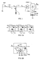
- FIG. 1 illustrates such a known configuration. The figure will be described in greater detail below with reference to the description of embodiments of the invention.
- FIG. 2A illustrates schematically, in the form of a single-line diagram, one such known configuration.
- the series capacitor comprises a number of sections C1, C2, C3, each one being connected in parallel with a fixed inductor, L11, L12, L13, respectively, and an inductor, L21, L22, L23, respectively, which may be temporarily connected by means of a switching member S21, S22, S23, respectively.
- Switching members S11, S12, S13 make possible connection and disconnection of individual sections.
- additional damping is possible by controlling the current through the parallel-connected inductor by means of a thyristor switch comprising two thyristors in anti-parallel connection.
- a device of this kind is usually referred to as a thyristor-controlled series capacitor, or a TCSC, and is schematically illustrated in the form of a single-line diagram in Figure 2B .
- a capacitor C is connected in parallel with an inductor L and a controllable semiconductor valve TYSW, the last-mentioned components being mutually series-connected.
- the semiconductor valve comprises two thyristors, TY1 and TY2, respectively, in anti-parallel connection.
- the semiconductor is supplied with firing pulses TP1, TP2 which bring the respective thyristors to the conducting state at firing instants determined by control equipment (not shown).
- control members for controlling the firing instants for the semiconductor valve in a TCSC.
- the control members comprise a command signal-generating member, preferably a phase-locked loop synchronized to the current through the transmission line, which phase-locked loop delivers equidistant command signals which are substantially independent of subsynchronous components and which are used as reference times for initiation of firing pulses for the semiconductor valve.
- a calculating circuit is adapted, based on these reference times in dependence on the instantaneous values of the line current and the capacitor voltage, to determine the firing instants in such a way that the instants for the zero crossings of the capacitor voltage occur with a constant time delay relative to the reference times.
- the zero crossings thus become substantially equidistant also in the presence of subsynchronous components in the current through the transmission line.
- the method comprises damping or completely preventing subsynchronous resonant oscillations, independently of a superordinate control of the effective impedance of the series capacitor at the fundamental frequency.
- the firing instants for the semiconductor valve must be synchronized with respect to either the voltage across or the current through the capacitor. This is done conventionally by bringing a phase-locked loop to generate a signal related to the phase position for the fundamental tone of one of these quantities.
- FIGS 3 and 4 which will be described in greater detail below with reference to the description of embodiments of the invention, schematically illustrate, respectively, known control equipment for a TCSC and typical signal shapes in such control equipment.
- a phase-locked loop usually comprises a low-pass filter which limits its bandwidth, that is, its ability to rapidly reproduce a change in the phase position of the current. Typically, this bandwidth is in the interval of 10-40 Hz.
- Thyristor-controlled series capacitor equipment which is connected between an ac network and a converter connected to the ac network, is subjected to rapid transients in the phase position of the current, in particular during operational disturbances such as, for example, when the converter temporarily loses its load and thereafter resumes it.
- Such a situation may, for example, arise when the converter is blocked in connection with a line fault and then, when the fault has been cleared, resumes operation as soon as possible.
- a situation may arise whereby the phase-locked loop does not provide the correct information about the present phase position of the current, which leads to the semiconductor valve being fired at unsuitable firing instants, resulting in large and possibly harmful valve currents.
- WO 96 15573 A1 discloses a method and apparatus for the series compensation in a converter station for high voltage DC transmission. Control equipment generates control angles for switches in the bridge and generates limiting signals to maintain a commutating margin in case of unbalance between capacitor voltages.
- the object of the invention is to provide control equipment of the kind described in the introductory part of the description, which is improved with respect to its ability for synchronization with the phase position of the current through the series capacitor equipment, in particular when this phase position undergoes rapid changes, and a method for control of the series capacitor equipment.
- the dynamic performance of the thyristor-controlled series capacitor depends to a great extent on whether reliable and rapid information about the phase position of the applied current is available. Such information is available at the earliest in the control device of the converter as a measure of the control angle thereof.
- a control device forms a control-angle order for phase-angle control of the converter, related to the phase position for a voltage at a chosen connection point
- the control equipment which comprises control means which in dependence on a synchronization signal forms firing pulses for control of the semiconductor valve, comprises phase-correcting means forming the synchronization signal in dependence on a voltage-phase signal applied thereto, which contains information about the phase position for the voltage in question, and on a control-angle signal supplied thereto, which contains information about the control angle of the converter.
- control equipment forms the synchronization signal in dependence also on a dc signal supplied thereto, which contains information about the amplitude for a sensed direct current through the converter.
- control means form the firing pulses for control of the semiconductor valve in dependence on an ac signal, containing information about the instantaneous amplitude of a sensed alternating current flowing through the series capacitor equipment, and on the ac voltage signal, containing information about the instantaneous amplitude for a sensed ac voltage across the series capacitor equipment.
- control equipment comprises a controller for control of the fundamental-tone reactance of the series capacitor equipment in dependence on a difference of a reference value for the fundamental-tone reactance and an actual value thereof, supplied to the controller
- control equipment comprises reference-value forming means which form the reference value in dependence on a dc signal supplied to the control equipment and containing information about the amplitude for a sensed direct current through the converter.
- the following description relates both to the control equipment and to the method for control of the series capacitor equipment.
- the control equipment comprises calculating members, in the figures shown in the form of block diagrams, and it is to be understood that the input and output signals to the respective blocks may consist of signals or calculated values.
- the terms signal value and calculated value will therefore be used synonymously in the following.
- the block diagrams show measured values and blocks for forming certain calculated values which are used in other shown blocks - connecting lines between these measured values and these blocks have in certain cases been omitted in order not to burden the drawings, but it is to be understood that the respective calculated values are obtained from the blocks in which they are formed and that measured values are formed in some way known per se by sensing corresponding quantities in the installation which comprises series capacitor equipment and converters.
- Figure 1 illustrates, in the form of a single-line diagram, a known configuration of a series-compensated converter.
- a thyristor converter CONV is connected, via a converter transformer T and a series capacitor C, to a three-phase ac network NET, shown in the figure only as a voltage busbar UL.
- the converter transformer has a Y-connected and a ⁇ -connected secondary winding, each one being connected to a respective one of two series-connected line-commutated six-pulse valve bridges, comprised in the converter but not shown in the figure.
- the converter has a dc voltage Ud and delivers to a dc circuit (not shown), which may comprise a converter of the same kind, a direct current Id.
- a control device CTR1 forms, in some manner known per se, in dependence on the dc voltage and the direct current, a control-angle order ⁇ - ORD, related to the voltage UL, which control-angle order is supplied to the valves of the converter for phase-angle control thereof.
- An alternating current IT flows to the converter.
- a shunt filter F for filtering harmonics in the alternating current is connected to a connection point J2 located on the primary side of the converter transformer, that is, between the converter transformer and the series capacitor.
- the voltage at the connection point J2 is designated U J2 and the current IF flows through the filter.
- the current IL through the series capacitor thus consists of the sum of the currents IF and IT.
- the voltage across the series capacitor is designated UC.
- FIG. 3 illustrates, in the form of a block diagram, a known embodiment of control equipment for thyristor-controlled series capacitor equipment CEQ.
- the series capacitor equipment comprises a capacitor C, connected in parallel with an inductor L and a controllable semiconductor valve TYSW.
- the inductor and the semiconductor valve are mutually series-connected.
- the semiconductor valve comprises two thyristors, TY1 and TY2, respectively, in antiparallel connection.
- the semiconductor valve is supplied with firing pulses TP1 and TP2, which bring the thyristor TY1 and the thyristor TY2, respectively, into the conducting state at firing instants determined by control equipment CTREQ'.
- the series capacitor equipment is connected to a three-phase ac network NET, in the figure only shown as a voltage busbar with the voltage UL.
- the network has a fundamental frequency, usually 50 or 60 Hz, to which an angular frequency ⁇ and a cycle time T correspond.
- a current IL flows from the ac network to the series capacitor equipment and is sensed with a current measuring device MI.
- the current through the inductor L is designated IV.
- the conducting direction for the thyristor TY2 coincides with the reference direction for the current IL, chosen in the figure.
- the measured value of the current is supplied to a phase-locked circuit 31 comprised in the control equipment.
- This circuit forms a synchronization signal ⁇ SYNC , which is saw-tooth shaped such that, under stationary conditions during a period T corresponding to 2 ⁇ electric radians of the current, it grows linearly from the value zero to a value 2 ⁇ , whereupon it returns to the value zero.
- the value zero thereby coincides, in steady state, with the positive zero crossing of the current
- the horizontal axis is graduated in the electrical angle of the current IL
- the vertical axis shows the current IL, expressed in per units, as well as the synchronization signal ⁇ SYNC .
- the figure illustrates the above-described relationship between the current IL and the synchronization signal ⁇ SYNC .
- the synchronization signal and a first trigger signal ⁇ TRI and a second trigger signal ⁇ TR2 are supplied to a trigger unit 32, comprising a comparing member 321 and a pulse-generating member 322.
- the trigger unit forms a first firing pulse TP1 when the value of the synchronization pulse corresponds to the value of the first trigger signal and a second firing pulse TP2 when the value of the synchronization signal corresponds to the value of the second trigger signal, whereby the firing pulse TP1 brings the thyristor TY1 into the conducting state and the firing pulse TP2 brings the thyristor TY2 into the conducting state.
- a summing member S1 is supplied with a first reference signal ⁇ R1 and a deviation signal ⁇ D , which will be explained in greater detail below, and forms as output signal the trigger signal ⁇ TRI as the difference of the reference and deviation signals (a circle at a signal input at the summing member denotes that this signal input is a negating input).
- a summing member S2 is supplied with a second reference signal ⁇ R2 and the deviation signal ⁇ D .
- the firing pulse TP1 will be formed when the fundamental tone for the current IL has its maximum positive value whereas the firing pulse TP2 will be formed when this fundamental tone has its maximum negative value. Since the capacitor voltage at these times is, in principle, equal to zero, the valve current IV will therefore be, in principle, equal to zero. This is illustrated in Figure 4 in the sub-interval ⁇ 0, 2 ⁇ ) of the first horizontal axis.
- a summing member S3 is supplied with and forms the difference of a reference value XR of a quantity X and the actual value XA of this quantity.
- the difference is supplied to a superordinate controller 33 which, in dependence thereon, forms the deviation signal ⁇ D .
- the quantity X is related to the series capacitor equipment and may typically consist of the fundamental-tone reactance thereof, which fundamental-tone reactance, in some manner known per se, is determined based on sensed values of the line current and the voltage across the capacitor.
- FIG. 5 shows, in the form of a block diagram, a preferred embodiment of the invention.
- the figure shows thyristor-controlled series capacitor equipment CEQ of the kind described with reference to Figure 3 , a shunt filter F, a converter transformer T and a thyristor converter CONV of the kind described with reference to Figure 1 , as well as control equipment CTREQ according to the invention.
- the shunt filter contrary to the one shown in Figure 1 , is not connected to the connection point J2 but to a connection point J1 located between the ac network and the series capacitor equipment.
- the alternating current through the series capacitor equipment is therefore, in this configuration, the same as the alternating current IT flowing via the converter transformer to the converter.
- the control device CTR1 of the converter forms, in a conventional way, a converter synchronization signal which is synchronized to the phase position for a voltage chosen in the ac circuit and sensed there, and a control-angle order ⁇ - ORD with a phase delay ⁇ in relation to this converter synchronization signal.
- the valves of the converter are brought into the conducting state in dependence on the control-angle order and the alternating current through the converter therefore becomes phase-shifted by an angle ⁇ relative to the voltage sensed in the ac circuit.
- the phase-locked circuit forms a voltage-phase signal ⁇ U , which is saw-tooth shaped in a manner similar to that of the synchronization signal described with reference to Figure 3 , but with the difference that its value zero is locked to the positive zero crossing of the voltage U J2
- the control-angle order is formed in dependence on the voltage-phase signal in that part of the control device which is designated 51' in the figure.
- the horizontal axis is graduated in the elecrical angle of the current IT and the vertical axis shows the voltage U J2 and the current IT , expressed in per units, as well as the voltage-phase signal ⁇ U and the synchronization signal ⁇ SYNC for the series capacitor equipment, which according to the invention is formed in a manner which will be described in greater detail below.
- Figure 6 illustrates a relationship where the current IT has a phase position an electrical angle ⁇ after the phase position of the voltage U J2 and illustrates the above-described relationships between the voltage U J2 , the current IT, the voltage-phase signal ⁇ U (dashed line) and the synchronization signal ⁇ SYNC (continuous line).
- the voltage-phase signal ⁇ U shown in Figure 6 is thus an example of a signal for synchronization of the control-angle order ⁇ - ORD with the phase position for the voltage at the connection point J2.
- the task according to the invention is to synchronize the firing instants for the thyristors comprised in the semiconductor valve TYSW to the current through the series capacitor equipment and thereby avoid the above-mentioned limitations exhibited by a phase-locked circuit with regard to its ability to rapidly reproduce a change in the phase position of the current.
- the synchronization signal ⁇ SYNC should be related in phase to the current IT through the series capacitor equipment as described above with reference to Figures 3 and 4 and also as illustrated in Figure 6 described in the following.
- the phase position for the alternating current in a network comprising a line-commutated converter is dependent, besides on the other components connected to this network, on the operating conditions of the converter, especially its control angle and its overlap angle.
- the latter angle is dependent on the direct current flowing through the converter and can be determined in a known manner when the line voltage and the commutating impedance are known.
- a change of the control angle ⁇ for the converter has a direct and immediate influence on the phase position of the alternating current.
- a current phase signal ⁇ is now created which is an at least approximate measure of the phase position of the current through the series capacitor equipment.
- IT 2 ⁇ 6 ⁇ ⁇ UV UT N ⁇ I d ⁇ e - j ⁇ ⁇ + ⁇ / 2
- UV is the voltage of the Y-connected and ⁇ -connected secondary windings, respectively, of the transformer T, corresponding to the nominal primary voltage UT N of the transformer (that is, in this embodiment the nominal voltage at the connection point J2), and the actual ratio of the transformer taking into consideration the occurrence of a tap-changer, ⁇ the control angle of the converter, I d the direct current through the converter and ⁇ its overlap angle.
- ⁇ is related to the voltage at the connection point J2.
- signals corresponding to the control angle ⁇ are available in conventional manner, and the overlap angle may be calculated, at least approximately, in a manner known per se, with knowledge of sensed values of the voltage of the ac network, the control angle and the direct current Id .
- a calculating member 52 comprised in the control equipment CTREQ is supplied with a control-angle signal ⁇ , formed in the control device of the converter and containing information about the instantaneous value of the control angle, and, in this embodiment, sensed values of the voltage U J2 of the ac network and a dc signal ⁇ d containing information about the amplitude of the direct current Id .
- a summing member S4 is supplied with and forms as output signal the difference of the voltage-phase signal ⁇ U and the current-phase signal ⁇ I , which difference thus constitutes the desired synchronization signal ⁇ SYNC for the series capacitor equipment. Otherwise, the control equipment CTREQ operates as described with reference to Figure 3 in dependence on the reference signal ⁇ R 1 and ⁇ R 2 as well as the deviation signal ⁇ D .
- phase position for the current IT is marked as an angle ⁇ between the voltage U J2 and the current IT .
- the voltage-phase signal may be suitable to relate the voltage-phase signal to some other connection point in the ac circuit, for example to the voltage UL for the ac network, that is, in a configuration according to Figure 5 , the voltage at the connection point J1, located between the ac network and the series capacitor equipment.
- the converter synchronization signal of the converter is then of course synchronized to the phase position for the voltage at the connection point J1, whereby also its control-angle order ⁇ - ORD and the information about the control angle, available in the control device of the converter, become related to this voltage.
- UV is the voltage of, respectively, the Y-connected and ⁇ -connected secondary windings of the transformer T, corresponding to the nominal primary voltage UT N of the transformer, and the actual ratio of the transformer taking into consideration the occurrence of a tap-changer
- UT N the nominal voltage for the primary side of the transformer (the RMS value of the principal voltage)
- U J2 the nominal voltage at the connection point J2
- ⁇ the control angle of the converter I d the direct current through the converter, ⁇ its overlap angle
- Q FN is the nominal reactive power of the filter at the fundamental frequency.
- phase position for the current IL flowing through the series capacitor relative to the voltage at the connection point J2 may thus be determined from expression (3) as follows arg 2 ⁇ 6 ⁇ ⁇ UV UT N ⁇ I d ⁇ e - j ⁇ ⁇ + ⁇ / 2 + j ⁇ Q FN UT N 2 U J ⁇ 2 3 where arg designates the argument for the complex expression (4).
- the quantities UV, UT N and Q FN are known from the calculated data of the installation.
- the voltage generated by the series capacitor equipment enforces an undesired oversizing of the converter with respect to voltage.
- the superordinate controller 33 is a controller for the fundamental-tone reactance X of the series capacitor equipment
- the reference value XR for the fundamental-tone reactance X of the series capacitor equipment may be reduced by a correction value XRC , formed in dependence on the direct current Id through the converter.
- a dc signal ⁇ d containing information about the amplitude for the direct current through the converter, is supplied to a function-forming member 53, which forms the correction value XRC when the direct current exceeds a predetermined value.
- this predetermined value may correspond to the nominal value of the direct current for the installation and the correction value XRC is formed in such a way that it grows linearly with the direct current across this predetermined value.
- FIG. 7 illustrates schematically an embodiment of this further development, where, for the sake of simplicity, of the control equipment CTREQ of the series capacitor as it is described above with reference to Figure 5 , only the trigger unit 32, the trigger signals ⁇ TR 1 and ⁇ TR 2 and the synchronization signal ⁇ SYNC are shown. It is to be understood that the signals ⁇ TR 1 , ⁇ TR 2 and ⁇ SYNC are formed according to the invention, for example in a way described above with reference to Figure 5 .
- a summing member S5 being supplied with, and forming as an output signal, the difference of the trigger signal ⁇ TR 1 and the angle ⁇ dp 0 and by a summing member S6 being supplied with, and forming as an output signal, the difference of the trigger signal ⁇ TR 2 and the angle ⁇ dp 0 .
- the output signals from the summing members S5 and S6, respectively, are supplied to the trigger unit 32.
- the angle ⁇ dp 0 is thus here equal to 2 ⁇ f*tdp 0 , where f is the fundamental frequency of the ac network NET.
- This calculating member is adapted, in a manner described in patent document EP 0 689 272 A1 in dependence on measured values IT ⁇ of the current IT through the series capacitor equipment (se Figure 7 ) and UC ⁇ of the capacitor voltage, respectively, in a manner similar to that described in EP 0 689 272 A1 , to form an influencing signal ST corresponding to the time delay tdp illustrated with reference to Figure 8 of EP 0 689 272 A1 .
- the formation of the influencing signal is initiated by the firing pulses TP1 and TP2.
- the firing pulses TP1 formed by the trigger unit 32 are supplied to a delay member 72, and the firing pulses TP2 formed by the trigger unit 32 are supplied to a delay member 73.
- the influencing signal ST is supplied to each of the delay members, the time delay of which, t , may be influenced in dependence on the influencing signal.
- the output signals TP1' and TP2' from the delay members are supplied to the controllable semiconductor valve TYSW to bring the.thyristor TY1 and the thyristor TY2, respectively, into the conducting state.
- the output signals from the delay members, which output signals are formed in the manner described correspond to the firing pulses TP1 and TP2, respectively, delayed by the time delay tdp .
- Subsynchronous resonant oscillations will thereby, in a manner described in patent document EP 0 689 272 A1 be damped or completely prevented independently of a superordinate control of the effective impedance of the series capacitor at the fundamental frequency.
- one configuration which is used comprises connecting series capacitor equipment between the converter transformer and the converter, in a 12-pulse converter then in such a way that one piece of series capacitor equipment is connected to the Y-connected secondary winding of the converter transformer and one piece of equipment is connected to the ⁇ -connected winding of the converter transformer.
- correction value XRC described with reference to Figure 5 may be formed in dependence on a current sensed at some other connection point in the installation, which is representative of the current through the series capacitor equipment.
- the series capacitor equipment may in an installation be series-connected to one or more fixed and/or connectable capacitors.
Landscapes
- Engineering & Computer Science (AREA)
- Power Engineering (AREA)
- Rectifiers (AREA)
- Supply And Distribution Of Alternating Current (AREA)
- Power Conversion In General (AREA)
- Control Of Electrical Variables (AREA)
Claims (13)
- Kontrollgerätschaft (CTREQ) zum Kontrollieren einer thyristor-kontrollierten Reihenkondensatorgerätschaft (CEQ), wobei die Gerätschaft zwischen einem Wechselstromnetzwerk (NET) und einem Konverter (CONV) verbunden ist, wobei der Konverter einen Wechselstrom (IT) in einen Hochspannungsgleichstrom (Id) konvertiert und der Konverter ein Kontrollgerät (CTR1) hat, das einen Kontrollwinkelbefehl (α-ORD) für Phasenwinkelkontrolle des Konverters (CONV) bildet bezogen auf die Phasenlage für eine Spannung (UJ2) bei einem gewählten Verbindungspunkt (J2), wobei die Reihenkondensatorgerätschaft (CEQ) ein kontrollierbares Halbleiterventil (TYSW) umfasst und die Kontrollgerätschaft (CTREQ) Kontrollmittel (32) hat, welche in Abhängigkeit von einem Synchronisationssignal (ΦSYNC) feuernde Pulse (TP1, TP2) zur Kontrolle des Halbleiterventils bilden, dadurch gekennzeichnet, dass die Kontrollgerätschaft (CTREQ) Phasenkorrekturmittel (52, S4) umfasst, die das Synchronisationssignal (ΦSYNC) bilden in Abhängigkeit von einem Spannungsphasensignal (ΦU), welches dorthin geliefert wird und Information über die Phasenlage der Spannung enthält, und von einem Kontrollwinkelsignal (α̃), das dorthin geliefert wird und Information über den Kontrollwinkel des Konverters enthält.
- Kontrollgerätschaft nach Anspruch 1, dadurch gekennzeichnet, dass die Phasenkorrekturmittel das Synchronisationssignal auch in Abhängigkeit von einem Gleichstromsignal (Ĩ d) bilden, das dorthin geliefert wird und Information über die Amplitude eines gespürten Gleichstroms (Id) durch den Konverter enthält.
- Kontrollgerätschaft nach einem der vorhergehenden Ansprüche, dadurch gekennzeichnet, dass die Kontrollmittel (32) die feuernden Pulse zur Kontrolle des Halbleiterventils in Abhängigkeit von einem Wechselstromsignal (I
T̃ ) bilden, das an die Kontrollgerätschaft geliefert wird und Information über die momentane Amplitude eines gespürten Wechselstroms (IT) enthält, der durch die Reihenkondensatorgerätschaft fließt, und von einem Wechselspannungssignal (UC̃ ), das an die Kontrollgerätschaft geliefert wird und Information über die momentane Amplitude einer gespürten Wechselspannung (UC) über die Reihenkondensatorgerätschaft hinweg enthält. - Kontrollgerätschaft nach einem der vorhergehenden Ansprüche, umfassend einen Controller (33) zum Kontrollieren der Grundtonreaktanz (X) der Reihenkondensatorgerätschaft in Abhängigkeit von einer Differenz zwischen einem Referenzwert (XR) der Grundtonreaktanz und einem tatsächlichen Wert (XA) davon, der an den Controller geliefert wird, dadurch gekennzeichnet, dass die Kontrollgerätschaft Referenzwertbildungsmittel (53, S7) umfasst, die den Referenzwert in Abhängigkeit von einem Gleichstromsignal (Ĩ d) bilden, das an die Kontrollgerätschaft geliefert wird und Information über die Amplitude eines gespürten Gleichstroms (Id) durch den Konverter enthält.
- Kontrollgerätschaft nach Anspruch 4, dadurch gekennzeichnet, dass die Referenzwertbildungsmittel den Referenzwert für die Grundtonreaktanz der Reihenkondensatorgerätschaft reduzieren, wenn das Gleichstromsignal Information enthält, dass die Amplitude des Gleichstroms einen vorbestimmten Wert übersteigt.
- Kontrollgerätschaft nach einem der vorhergehenden Ansprüche, dadurch gekennzeichnet, dass sie Mittel (S5, S6, 71, 72, 73) umfasst zum Kontrollieren der zeitlichen Augenblicke für das Halbleiterventil, so dass die Zeiten für Nullkreuzungen der Spannung (UC) über die Kondensatorgerätschaft hinweg im Wesentlichen äquidistant werden, auch wenn der Strom (IT) dort hindurch zusätzlich zu seiner Grundkomponente auch subsynchrone Komponenten enthält.
- Eine elektrische Einrichtung umfassend einen Konverter (CONV), verbunden mit einem Wechselstromnetzwerk (NET), zur Konversion zwischen Wechselstrom (IT) und Hochspannungsgleichstrom (Id), und eine thyristor-kontrollierte Reihenkondensatorgerätschaft (CEQ), die zwischen dem Wechselstromnetzwerk und dem Konverter verbunden ist, wobei der Konverter ein Kontrollgerät (CTR1) umfasst, das einen Kontrollwinkelbefehl (α-ORD) zur Phasenwinkelkontrolle des Konverters bildet, bezogen auf die Phasenlage für eine Spannung (UJ2) bei einem gewählten Verbindungspunkt (J2), wobei die Reihenkondensatorgerätschaft ein kontrollierbares Halbleiterventil (TYSW) hat und Kontrollgerätschaft mit Kontrollmitteln hat, die in Abhängigkeit von einem Synchronisationssignal (ΦSYNC) feuernde Pulse (TP1, TP2) zur Kontrolle des Halbleiterventils bilden, dadurch gekennzeichnet, dass die Einrichtung Kontrollgerätschaft gemäß einem der vorhergehenden Ansprüche umfasst.
- Ein Verfahren zur Kontrolle einer thyristor-kontrollierten Reihenkondensatorgerätschaft (CEQ), beabsichtigt für die Verbindung zwischen einem Wechselstromnetzwerk (NET) und einem damit verbundenen Konverter (CONV) für die Konvertierung zwischen Wechselstrom (IT) und Hochspannungsgleichstrom (Id), wobei die Reihenkondensatorgerätschaft ein kontrollierbares Halbleiterventil (TYSW) hat, wobei
ein Kontrollwinkelbefehl (α-ORD) bezogen auf die Phasenlage für eine Spannung (UJ2) bei einem gewählten Verbindungspunkt (J2) für Phasenwinkelkontrolle des Konverters gebildet wird und
feuernde Pulse (TP1, TP2) zur Kontrolle des Halbleiterventils in Abhängigkeit von einem Synchronisationssignals (ΦSYNC) gebildet werden,
dadurch gekennzeichnet, dass
das Synchronisationssignal (ΦSYNC) gebildet wird in Abhängigkeit von einem Spannungsphasensignal (ΦU), welches Information über die Phasenlage für die Spannung enthält, und von einem Kontrollwinkelsignals (α̃), welches Information über den Kontrollwinkel des Konverters enthält. - Ein Verfahren nach Anspruch 8, dadurch gekennzeichnet, dass das Synchronisationssignal auch in Abhängigkeit von der Amplitude für einen gespürten Gleichstrom (Id) durch den Konverter gebildet wird.
- Ein Verfahren nach einem der Ansprüche 8-9, dadurch gekennzeichnet, dass die feuernden Pulse zur Kontrolle des Halbleiterventils in Abhängigkeit von der momentanen Amplitude für einen gespürten Wechselstrom (IT) gebildet werden, der durch die Reihenkondensatorgerätschaft fließt, und von der momentanen Amplitude für eine gespürte Wechselspannung (UC) über die Reihenkondensatorgerätschaft hinweg.
- Ein Verfahren nach einem der Ansprüche 8-10, dadurch gekennzeichnet, dass die feuernden Pulse zur Kontrolle des Halbleiterventils auch in Abhängigkeit von einer Differenz zwischen einem Referenzwert (XR) für die Grundtonreaktanz der Reihenkondensatorgerätschaft und einem tatsächlichen Wert (XA) davon gebildet werden, wobei der Referenzwert in Abhängigkeit von der Amplitude eines gespürten Gleichstroms (Id) durch den Konverter gebildet wird.
- Ein Verfahren nach Anspruch 11, dadurch gekennzeichnet, dass der Referenzwert für die Grundtonreaktanz der Reihenkondensatorgerätschaft reduziert wird, wenn die Amplitude des Gleichstroms einen vorbestimmten Wert übersteigt.
- Ein Verfahren nach einem der Ansprüche 8-12, dadurch gekennzeichnet, dass die zeitlichen Augenblicke für das Halbleiterventil kontrolliert werden, so dass die Zeiten für Nullkreuzungen der Spannung (UC) über die Kondensatorgerätschaft hinweg im Wesentlichen äquidistant werden, auch wenn der Strom (IT) dort hindurch zusätzlich zu seiner Grundkomponente auch subsynchrone Komponenten enthält.
Applications Claiming Priority (3)
| Application Number | Priority Date | Filing Date | Title |
|---|---|---|---|
| SE9903401 | 1999-09-22 | ||
| SE9903401A SE514965C2 (sv) | 1999-09-22 | 1999-09-22 | Kontrollutrustning för en tyristorstyrd seriekondensatorutrustning, och förfarande för styrning därav |
| PCT/SE2000/001671 WO2001024342A1 (en) | 1999-09-22 | 2000-08-31 | Control equipment for thyristor-controlled series capacitor equipment, and a method for control thereof |
Publications (2)
| Publication Number | Publication Date |
|---|---|
| EP1145401A1 EP1145401A1 (de) | 2001-10-17 |
| EP1145401B1 true EP1145401B1 (de) | 2009-11-04 |
Family
ID=20417087
Family Applications (1)
| Application Number | Title | Priority Date | Filing Date |
|---|---|---|---|
| EP00964828A Expired - Lifetime EP1145401B1 (de) | 1999-09-22 | 2000-08-31 | Steuereinrichtung fuer thyristor gesteuerte reihenkondensatoreinrichtung, und zugehoeriges steuerverfahren |
Country Status (6)
| Country | Link |
|---|---|
| US (1) | US6404656B1 (de) |
| EP (1) | EP1145401B1 (de) |
| JP (1) | JP4203242B2 (de) |
| DE (1) | DE60043257D1 (de) |
| SE (1) | SE514965C2 (de) |
| WO (1) | WO2001024342A1 (de) |
Families Citing this family (13)
| Publication number | Priority date | Publication date | Assignee | Title |
|---|---|---|---|---|
| UA84185C2 (ru) * | 2003-12-12 | 2008-09-25 | Коултек Корпорейшн | Способ и установка для обработки сырового твердого топлива |
| EP1966867B1 (de) * | 2005-12-28 | 2014-03-05 | Abb Research Ltd. | Thyristorgesteuertes serienkondensatormodul |
| US8585786B2 (en) * | 2006-03-31 | 2013-11-19 | Coaltek, Inc. | Methods and systems for briquetting solid fuel |
| US8585788B2 (en) * | 2006-03-31 | 2013-11-19 | Coaltek, Inc. | Methods and systems for processing solid fuel |
| EP2022154B1 (de) * | 2006-05-30 | 2015-10-14 | Abb Research Ltd. | Für die dämpfung von subsynchronresonanzen ausgelegter thyristorgesteuerter reihenkondensator |
| CN101675569B (zh) * | 2007-05-18 | 2013-09-18 | Abb技术有限公司 | 静态无功补偿器设备 |
| US8063515B2 (en) * | 2008-10-10 | 2011-11-22 | General Electric Company | Compensation system for power transmission |
| WO2011029480A1 (en) * | 2009-09-11 | 2011-03-17 | Abb Research Ltd | Fault current limitation in dc power transmission systems |
| EP2543124B1 (de) | 2010-03-04 | 2013-08-21 | ABB Research LTD | Wechselstrom-/gleichstrom-wandleranlage und verfahren zum betrieb einer wechselstrom-/gleichstrom-wandleranlage |
| EP2388471A1 (de) * | 2010-05-21 | 2011-11-23 | AEG Power Solutions B.V. | Schaltungsanordnung zur Folgesteuerung von Leistungsstellern mit einem Verteilen von Zündimpulsen |
| WO2014206462A1 (en) * | 2013-06-26 | 2014-12-31 | Abb Technology Ltd | A power converter and associated method |
| CN103746391B (zh) * | 2014-02-18 | 2016-03-16 | 济南银河电气有限公司 | 一种磁控电抗器初次触发控制方法 |
| US9467112B2 (en) | 2014-07-25 | 2016-10-11 | Ge Energy Power Conversion Technology Ltd | Hybrid thyristor-controlled series capacitor and passive damping filter for series capacitors |
Family Cites Families (8)
| Publication number | Priority date | Publication date | Assignee | Title |
|---|---|---|---|---|
| US4028607A (en) * | 1974-04-22 | 1977-06-07 | Hitachi, Ltd. | Inverter control system |
| JPS51102547A (de) * | 1975-03-07 | 1976-09-10 | Hitachi Ltd | |
| JPS5920261B2 (ja) * | 1980-05-07 | 1984-05-11 | 株式会社東芝 | 無停電電源装置 |
| US4866592A (en) * | 1988-03-30 | 1989-09-12 | Fuji Electric Co., Ltd. | Control system for an inverter apparatus |
| US5424627A (en) | 1991-12-13 | 1995-06-13 | Electric Power Research Institute | Modular thyristor controlled series capacitor control system |
| SE514826C2 (sv) | 1994-10-13 | 2001-04-30 | Abb Ab | Förfarande och anordning för styrning av en seriekompenserad strömriktarstation |
| SE503374C2 (sv) | 1994-11-15 | 1996-06-03 | Asea Brown Boveri | Förfarande och anordning för styrning av en i en anläggning för överföring av högspänd likström ingående seriekompenserad strömriktarstation |
| US5804949A (en) * | 1995-03-23 | 1998-09-08 | Asea Brown Boveri Ab | Thyristor-controlled series capacitor triggering system |
-
1999
- 1999-09-22 SE SE9903401A patent/SE514965C2/sv not_active IP Right Cessation
-
2000
- 2000-08-31 JP JP2001527418A patent/JP4203242B2/ja not_active Expired - Fee Related
- 2000-08-31 EP EP00964828A patent/EP1145401B1/de not_active Expired - Lifetime
- 2000-08-31 WO PCT/SE2000/001671 patent/WO2001024342A1/en not_active Ceased
- 2000-08-31 US US09/831,882 patent/US6404656B1/en not_active Expired - Fee Related
- 2000-08-31 DE DE60043257T patent/DE60043257D1/de not_active Expired - Lifetime
Also Published As
| Publication number | Publication date |
|---|---|
| US6404656B1 (en) | 2002-06-11 |
| SE9903401L (sv) | 2001-03-23 |
| WO2001024342A1 (en) | 2001-04-05 |
| SE9903401D0 (sv) | 1999-09-22 |
| JP4203242B2 (ja) | 2008-12-24 |
| SE514965C2 (sv) | 2001-05-21 |
| JP2003511001A (ja) | 2003-03-18 |
| DE60043257D1 (de) | 2009-12-17 |
| EP1145401A1 (de) | 2001-10-17 |
Similar Documents
| Publication | Publication Date | Title |
|---|---|---|
| Ramachandaramurthy et al. | Control of a battery supported dynamic voltage restorer | |
| US6400585B2 (en) | Method and control system for voltage control at a converter station | |
| Malesani et al. | Active filter for reactive power and harmonics compensation | |
| US5969509A (en) | Method and a device for control of a capacitor device for a shunt-connected compensator unit | |
| Ainsworth | The phase-locked oscillator-a new control system for controlled static convertors | |
| EP1145401B1 (de) | Steuereinrichtung fuer thyristor gesteuerte reihenkondensatoreinrichtung, und zugehoeriges steuerverfahren | |
| US6144191A (en) | Voltage regulator | |
| US5627735A (en) | Method and device for compensation of unbalance in a series compensated converter station | |
| EP0802618B1 (de) | Regelanordnung für einen Mehrpegelumrichter | |
| Chen et al. | Dynamic performance of PWM STATCOMs operating under unbalance and fault conditions in distribution systems | |
| EP0769221B1 (de) | Lastkommutierter synchroner motorantrieb | |
| Ekstrom et al. | HVDC tapping station: power tapping from a DC transmission line to a local AC network | |
| An et al. | Assessment of two different STATCOM configurations for FACTS application in power systems | |
| Biricik et al. | Sliding mode control strategy for three-phase DVR employing twelve-switch voltage source converter | |
| US7173349B2 (en) | Equipment and method for exchanging power, in shunt connection, with an electric power network, and use of such equipment | |
| US4001670A (en) | Static reactive power generating apparatus | |
| EP0858141B1 (de) | Verfahren und Vorrichtung zur Steuerung einer kapazitiven Vorrichtung für eine Nebenschluss-Kompensatoreinheit | |
| Alassouli | Control of flexible alternating current transmission system (FACTS) for power stability enhancement and power quality improvement | |
| Eremia et al. | CSC–HVDC Transmission | |
| Qureshi et al. | Comparative analysis of unit template, SRF and the modified SRF technique for DSTATCOM-based distribution system | |
| Kolhatkar et al. | An Optimum UPQC with Minimum VA Requirement and Mitigation of Unbalanced Voltage Sag. | |
| Norheim | Suggested methods for preventing core saturation instability in HVDC transmission systems | |
| Meah | A self coordinating parallel multi-pi control scheme for an HVDC transmission system to accommodate a weak AC system | |
| Padiyar | Interactions with HVDC Converter Control | |
| SU1629953A1 (ru) | Устройство дл управлени преобразователем частоты |
Legal Events
| Date | Code | Title | Description |
|---|---|---|---|
| PUAI | Public reference made under article 153(3) epc to a published international application that has entered the european phase |
Free format text: ORIGINAL CODE: 0009012 |
|
| 17P | Request for examination filed |
Effective date: 20010507 |
|
| AK | Designated contracting states |
Kind code of ref document: A1 Designated state(s): AT BE CH CY DE DK ES FI FR GB GR IE IT LI LU MC NL PT SE |
|
| AX | Request for extension of the european patent |
Free format text: AL;LT;LV;MK;RO;SI |
|
| RBV | Designated contracting states (corrected) |
Designated state(s): DE FR GB SE |
|
| GRAP | Despatch of communication of intention to grant a patent |
Free format text: ORIGINAL CODE: EPIDOSNIGR1 |
|
| RIN1 | Information on inventor provided before grant (corrected) |
Inventor name: AENGQUIST, LENNART Inventor name: JONSSON, TOMAS |
|
| GRAS | Grant fee paid |
Free format text: ORIGINAL CODE: EPIDOSNIGR3 |
|
| GRAA | (expected) grant |
Free format text: ORIGINAL CODE: 0009210 |
|
| AK | Designated contracting states |
Kind code of ref document: B1 Designated state(s): DE FR GB SE |
|
| REG | Reference to a national code |
Ref country code: GB Ref legal event code: FG4D |
|
| REF | Corresponds to: |
Ref document number: 60043257 Country of ref document: DE Date of ref document: 20091217 Kind code of ref document: P |
|
| REG | Reference to a national code |
Ref country code: SE Ref legal event code: TRGR |
|
| PLBE | No opposition filed within time limit |
Free format text: ORIGINAL CODE: 0009261 |
|
| STAA | Information on the status of an ep patent application or granted ep patent |
Free format text: STATUS: NO OPPOSITION FILED WITHIN TIME LIMIT |
|
| 26N | No opposition filed |
Effective date: 20100805 |
|
| PGFP | Annual fee paid to national office [announced via postgrant information from national office to epo] |
Ref country code: GB Payment date: 20120829 Year of fee payment: 13 Ref country code: SE Payment date: 20120813 Year of fee payment: 13 |
|
| PGFP | Annual fee paid to national office [announced via postgrant information from national office to epo] |
Ref country code: FR Payment date: 20120823 Year of fee payment: 13 Ref country code: DE Payment date: 20120829 Year of fee payment: 13 |
|
| GBPC | Gb: european patent ceased through non-payment of renewal fee |
Effective date: 20130831 |
|
| REG | Reference to a national code |
Ref country code: SE Ref legal event code: EUG |
|
| PG25 | Lapsed in a contracting state [announced via postgrant information from national office to epo] |
Ref country code: SE Free format text: LAPSE BECAUSE OF NON-PAYMENT OF DUE FEES Effective date: 20130901 Ref country code: DE Free format text: LAPSE BECAUSE OF NON-PAYMENT OF DUE FEES Effective date: 20140301 |
|
| REG | Reference to a national code |
Ref country code: FR Ref legal event code: ST Effective date: 20140430 |
|
| REG | Reference to a national code |
Ref country code: DE Ref legal event code: R119 Ref document number: 60043257 Country of ref document: DE Effective date: 20140301 |
|
| PG25 | Lapsed in a contracting state [announced via postgrant information from national office to epo] |
Ref country code: GB Free format text: LAPSE BECAUSE OF NON-PAYMENT OF DUE FEES Effective date: 20130831 |
|
| PG25 | Lapsed in a contracting state [announced via postgrant information from national office to epo] |
Ref country code: FR Free format text: LAPSE BECAUSE OF NON-PAYMENT OF DUE FEES Effective date: 20130902 |