EP1145794B1 - Appareil pour l'acquisition de conditions de soudage - Google Patents
Appareil pour l'acquisition de conditions de soudage Download PDFInfo
- Publication number
- EP1145794B1 EP1145794B1 EP01108955A EP01108955A EP1145794B1 EP 1145794 B1 EP1145794 B1 EP 1145794B1 EP 01108955 A EP01108955 A EP 01108955A EP 01108955 A EP01108955 A EP 01108955A EP 1145794 B1 EP1145794 B1 EP 1145794B1
- Authority
- EP
- European Patent Office
- Prior art keywords
- welding condition
- value
- section
- welding
- item
- Prior art date
- Legal status (The legal status is an assumption and is not a legal conclusion. Google has not performed a legal analysis and makes no representation as to the accuracy of the status listed.)
- Expired - Lifetime
Links
Images


Classifications
-
- B—PERFORMING OPERATIONS; TRANSPORTING
- B23—MACHINE TOOLS; METAL-WORKING NOT OTHERWISE PROVIDED FOR
- B23K—SOLDERING OR UNSOLDERING; WELDING; CLADDING OR PLATING BY SOLDERING OR WELDING; CUTTING BY APPLYING HEAT LOCALLY, e.g. FLAME CUTTING; WORKING BY LASER BEAM
- B23K9/00—Arc welding or cutting
- B23K9/09—Arrangements or circuits for arc welding with pulsed current or voltage
-
- B—PERFORMING OPERATIONS; TRANSPORTING
- B23—MACHINE TOOLS; METAL-WORKING NOT OTHERWISE PROVIDED FOR
- B23K—SOLDERING OR UNSOLDERING; WELDING; CLADDING OR PLATING BY SOLDERING OR WELDING; CUTTING BY APPLYING HEAT LOCALLY, e.g. FLAME CUTTING; WORKING BY LASER BEAM
- B23K9/00—Arc welding or cutting
- B23K9/10—Other electric circuits therefor; Protective circuits; Remote controls
- B23K9/1006—Power supply
- B23K9/1043—Power supply characterised by the electric circuit
- B23K9/1056—Power supply characterised by the electric circuit by using digital means
- B23K9/1062—Power supply characterised by the electric circuit by using digital means with computing means
Definitions
- the present invention relates to equipment for inputting the welding conditions in a welder.
- the welding conditions are set as follows. First, a welding condition is selected by a switch. The selected welding condition is adjusted by a variable resistor provided for each welding condition. These welding conditions should be input before starting welding operation. When the material and thickness of the base metal and shape of the weld joint are complicated, the welding conditions are also complex.
- Fig. 13 is a structural example of a conventional arc welding condition inputting equipment (hereinafter called inputting equipment). For example, when an initial current of 200 A is necessary for initial arc welding, an initial control select switch 56 is set in "Yes" position. Then a variable resistor for initial current 51 is adjusted to a graduation of about 200 A.
- the welding current is set by a variable resistor for welding current 52.
- crater processing means welding for filling the crater (dimple) formed at the welding terminal end with depositing metal.
- a pulse control select switch 58 is set in "Yes" position. Then the pulse current and the pulse frequency are adjusted in a variable resistor for pulse current 54 and a variable resistor for pulse frequency 55. By the outputs from the variable resistors and switches, the welding conditions are set in an inputting section 59. Further, the inputting equipment requires a variable resistor for slope for forming an ascending or descending slope of current and voltage during arc welding.
- the total number of variable resistors and switches may exceed twenty. It hence involves possibility of setting error or failure when selecting the switches or adjusting the variable resistors.
- variable resistors are usually disposed closely in a narrow space. Therefore, at the time of setting, the operator may touch a wrong variable resistor and the adjusted position of the variable resistor may be deviated.
- variable resistor is adjusted at an approximate position, the welding conditions may not be always reproduced correctly at the time of re-adjustment. At every input of welding conditions, the user is required to always check the input values.
- the inputting equipment of the invention comprises an operating section for inputting the welding conditions, a determining section for selecting items, and a display section for displaying selected items.
- the operating section When the welding conditions are input, the operating section outputs the conditions to the determining section.
- the determining section selects items corresponding to the conditions, and outputs the items to the display section.
- the display section displays the items.
- the operating section specifically includes a dial, a switch, and a push-in dial switch integrally combining a dial rotation detecting part.
- This equipment is designed to set welding conditions including the initial current, initial voltage, welding current, welding voltage, pulse welding current, and pulse frequency.
- Fig. 1 is a block diagram showing a configuration of inputting equipment of the invention.
- the operating section 11 When a value relating to a welding condition is input in an operating section 11, the operating section 11 sends the condition into a determining section 13. When the condition is sent from the operating section 11 into the determining section 13, the determining section 13 selects an item to be displayed in a display section 15, from a group of items relating to welding conditions.
- Items relating to welding conditions include the following.
- the operating section makes adjustments for setting the item included in 1) and the input value of 2), and outputs the value being adjusted to the determining section 13 as the adjusting value.
- the determining section 13 sends the item to the display unit 15.
- the display unit 15 displays this item.
- Plural items may be also selected from the group of items relating to the welding conditions.
- the operating section 11 may be divided into plural units. By dividing the operating section into groups of items, the operating section may be easier to use for the user.
- Fig. 2 is a block diagram showing a configuration of inputting equipment of the invention.
- the same components as in the foregoing embodiment are identified with the same reference numerals.
- a dial 17 can be pushed in the direction of rotary shaft.
- a detector 19 detects the amount of rotation of the dial 17, and outputs a signal (a first signal) corresponding to the detected amount to a converter 23.
- the amount of rotation can be detected, for example, in one of the following known methods.
- a switch 21 is coupled to the dial 17. When the dial 17 is pushed in, the switch 21 sends a signal (a second signal) noticing the push-in operation to a setting section 25.
- the converting section 23 converts the signal output from the detector 19 to the value showing the amount of rotation sequentially as the adjusting value.
- the signal showing this numerical value is output to the setting section 25.
- the setting section 25 determines the numerical value from the converting section 23 as the input value of the welding condition being selected at the present.
- the selected welding condition is the same as the welding condition displayed in the display section 15.
- the setting section 25 selects a next welding condition to be input from the item group, and sends the signal of the welding condition to the display section 15.
- the welding conditions can be input. Further, the switch coupled to the dial can determine the selection of welding condition and also determine the input value. Therefore, if touching the dial unexpectedly, the input value is not deviated.
- the dial 17, detector 19, and switch 21 correspond to the operating section 11 in Fig. 1.
- the dial 17, detector 19, and switch 21 may be combined integrally into a push-in switch.
- Fig. 3 is a block diagram showing a configuration of inputting equipment of the invention.
- the same components as in the foregoing embodiments are identified with the same reference numerals.
- An increasing/decreasing value converting section 27 provides the signal output from a detector 19 with a sign corresponding to the rotating direction of the dial 17, and converts the signed signal sequentially into an increasing or decreasing value.
- the rotating direction of the dial 17 is detected by an increase or a decrease of the resistance value, for example, when the amount of rotation is converted into a resistance value.
- the increasing/decreasing value converting section 27 outputs the increasing or decreasing value into an adding section 29.
- the adding section 29 outputs the numerical value indicating the amount of rotation, which is obtained by adding the increasing or decreasing value sequentially on a reference value, to the setting section 25 as the adjusting value.
- the setting section 25 determines the numerical value indicating the amount of rotation output from the adding section 29 at this time, as the input value of the welding condition selected at present.
- the determining section 13 in the first exemplary embodiment, and the setting section 25 in the second and third exemplary embodiments may be designed as follows:
- the display section 15 is composed of LCD display or other display device.
- the determining section 13 in the first exemplary embodiment or the setting section 25 may show which step is conducted in the welding sequence, in the item of the welding condition selected at present, by means of the display section 15.
- the steps in the welding sequence includes, for example, initial welding, main welding, or crater welding.
- Fig. 4 is a block diagram showing a configuration of inputting equipment of the invention.
- the same components as in the foregoing embodiments are identified with the same reference numerals.
- the output of an operating section 11 is input into a determining section 13.
- the determining section 13 outputs the signal of the welding condition being selected at present to a LCD display 31. Receiving this signal, the LCD display 31 displays the welding condition according to its display capacity.
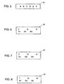
- Fig. 5 is a display example of welding conditions in one-line LCD display 31.
- A, B, C, D, E, F indicate items relating to the welding conditions.
- Fig. 6, Fig. 7, and Fig. 8 are display examples of welding conditions in LCD display 31 for displaying two lines or more.
- F, G, H denote group names of the grouped welding conditions. Specifically, F1, F2, F3 show welding conditions belonging to group F. Similarly, G1, G2, G3 show welding conditions belonging to group G, and H1, H2, H3, belonging to group H.
- the first line refers to the group name, and the second and subsequent lines indicate the welding conditions belonging to the specific group.
- the signal supplied into the LCD display 31 is the output from the determining section 13.
- the output from the setting section 25 included in the components of the determining section 13 may be also input.
- the first line of the LCD display 31 in Fig. 5 to Fig. 8 shows a fixed welding condition, but the display in the LCD display 31 can be changed by the signal input from the determining section 13.
- the LCD display 31 in Fig. 5 to Fig. 8 shows only the welding condition. However, by the signal input from the determining section 13, the LCD display 31 can change over the display between the value sequentially input from the operating section 11, and the welding condition.
- the value sequentially input from the operating section 11 and its welding condition may be displayed simultaneously in the LCD display 31.
- the value that needs to be set in the welding condition selected at present may be displayed in the LCD display 31.
- the welding conditions, sequentially input values, and necessary setting values in welding conditions can be displayed in the LCD display 31.
- the same effects as in the first exemplary embodiment are obtained. If the necessary setting values are controlled, the adjustment of input values is easy and accurate by referring to the values.
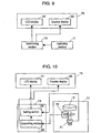
- Fig. 9 and Fig. 10 are block diagrams showing a configuration of inputting equipment of the invention.
- the same components as in the foregoing embodiments are identified with the same reference numerals.
- a counter display 35 (for example, 7-segment LED display device) is a second display unit, which shows the input value into the determining section 13 from the operating section 11.
- the LCD display 31 which is a first display unit, shows the items of welding conditions.
- the LCD display 31 may show the item to be set, or all items or related item group, and display the presently selected welding condition so that it may be identified (for example, a flicker display signal).
- the adjusting value is determined as input value. Together with the welding condition selected in the setting section 25, the input value is displayed in the LCD display 31.
- the signal input in the counter display 33 is output from the converting section 23, but it may be also output from the adding section 29 included in the components of the converting section 23.
- the setting section 25 displays the selected welding condition and the previous input value of the condition in the LCD display 31. At the same time, the setting section 25 can display the numerical value of the welding condition being presently adjusted in the counter display 33.
- the input value is determined for each item in the item group of the welding conditions.
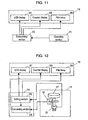
- Fig. 11 and Fig. 12 are block diagrams showing a configuration of inputting equipment of the invention.
- the same components as in the foregoing embodiments are identified with the same reference numerals.
- a pilot lamp 35 is a third display unit, which displays the welding sequence is in which state (for example, initial welding, main welding, or crater welding), in the welding condition being selected at present, output from the setting section 25.
- the third display unit is not limited to the pilot lamp, but may be realized by liquid crystal device, LED display or the like.
- whether the item of the welding condition is selected i) by selecting the item of the welding condition by the dial or ii) by selecting by the determining section 13 is determined by selecting either i) or ii) in the determining section 13.
- the determining section 13 presents items of welding conditions sequentially according to a preset program.
- the inputting equipment of the first to sixth exemplary embodiments is used in the welding machine of arc discharge type.
- the inputting equipment of the invention may be also applied in general welders, or peripheral devices of the welder (for example, wire feeder, remote controller, torch).
Landscapes
- Engineering & Computer Science (AREA)
- Physics & Mathematics (AREA)
- Plasma & Fusion (AREA)
- Mechanical Engineering (AREA)
- Theoretical Computer Science (AREA)
- Arc Welding Control (AREA)
- Arc Welding In General (AREA)
- Resistance Welding (AREA)
Claims (10)
- Equipement d'entrée de conditions de soudage comprenant :ladite section fonctionnelle comprend(a) une section fonctionnelle (11) destinée à recevoir des conditions de soudage et à fournir en sortie les conditions de soudage,(b) une section de détermination (13) destinée à recevoir des conditions de soudage, à sélectionner un élément correspondant aux conditions de soudage, et à fournir en sortie l'élément, et(c) une section d'affichage (15) destinée à afficher l'élément appliqué en entrée depuis ladite section de détermination, caractérisé en ce que(a1) un cadran (17) actionné en poussant dans un sens un arbre rotatif,(a2) un détecteur (19) destiné à détecter une quantité de rotation dudit cadran, et fournir en sortie un premier signal indiquant l'un de (i) une valeur numérique des conditions de soudage et (ii) un élément des conditions de soudage correspondant à la quantité de rotation, et(a3) un commutateur (21), couplé audit cadran, destiné à fournir en sortie un second signal lorsque l'on appuie sur ledit cadran.
- Equipement d'entrée de conditions de soudage selon la revendication 1, dans lequel
ladite section de détermination comprendoù,(b1) une section de conversion destinée à recevoir le premier signal et à convertir le premier signal en une valeur indiquant la quantité de rotation, et(b2) une section de réglage destinée à déterminer une valeur d'entrée en fonction des conditions de soudage correspondant à la valeur indiquant la quantité de rotation lors de la réception du second signal, et à sélectionner un élément suivant des conditions de soudage et à fournir en sortie un signal à ladite section d'affichage,1)i) dans le cas où le premier signal indique la valeur numérique des conditions de soudage, en utilisant la valeur indiquant la quantité de rotation comme valeur d'ajustement, ladite section de réglage établit la valeur d'ajustement en tant que valeur d'entrée lorsque le second signal est appliqué en entrée, et sélectionne l'élément suivant des conditions de soudage, ouii) dans le cas où ledit premier signal indique l'élément des conditions de soudage, ladite section de réglage sélectionne un élément qui est appliqué en entrée lorsque le second signal est appliqué en entrée, et2) ladite section de réglage fournit en sortie un signal indiquant au moins l'un de la valeur d'ajustement, de la valeur d'entrée et de l'élément sélectionné à ladite section d'affichage. - Equipement d'entrée de conditions de soudage selon la revendication 2,
dans lequel ladite section de conversion comprend :(b11) une section de conversion de valeur croissante/décroissante destinée à convertir ledit premier signal en une valeur croissante ou décroissante présentant un signe correspondant à un sens de rotation dudit cadran, et(b12) une section d'addition destinée à additionner la valeur croissante ou décroissante à une valeur de référence afin d'obtenir la valeur de l'ajustement. - Equipement d'entrée de conditions de soudage selon la revendication 2 ou 3, dans lequel ladite section de réglage fournit en outre en sortie un signal indiquant au moins l'un de i) un élément des conditions de soudage dont la valeur est établie actuellement, ii) un élément des conditions de soudage dont la valeur est établie ensuite, iii) la valeur d'ajustement, iv) la valeur d'entrée, et v) la valeur d'entrée déterminée précédente de la valeur d'entrée, à ladite section d'affichage.
- Equipement d'entrée de conditions de soudage selon la revendication 1,
dans lequel ladite section d'affichage comprend un dispositif d'affichage à cristaux liquides en tant que première unité d'affichage. - Equipement d'entrée de conditions de soudage selon l'une quelconque des revendications 2 à 4,
dans lequel ladite section d'affichage comprend un dispositif d'affichage à cristaux liquides en tant que première unité d'affichage. - Equipement d'entrée de conditions de soudage selon la revendication 6,
dans lequel ladite section d'affichage comprend une seconde unité d'affichage destinée à afficher au moins l'une de la valeur d'ajustement et de la valeur d'entrée. - Equipement d'entrée de conditions de soudage selon l'une quelconque des revendications 2, 3 et 7,
dans lequel ladite section d'affichage comprend une troisième unité d'affichage destinée à afficher un élément des conditions de soudage qui est exécuté actuellement dans une séquence de soudage. - Equipement d'entrée de conditions de soudage selon la revendication 7,
dans lequel i) jusqu'à ce que la valeur d'ajustement soit établie en tant que valeur d'entrée, ladite seconde unité d'affichage affiche la valeur d'ajustement, et ii) lorsque ledit second signal est appliqué en entrée dans ladite section de réglage, ledit dispositif d'affichage à cristaux liquides affiche l'élément des conditions de soudage sélectionnées. - Equipement d'entrée de conditions de soudage selon l'une quelconque des revendications 5 à 9,
dans lequel ledit dispositif d'affichage à cristaux liquides affiche des caractères sur plusieurs lignes.
Applications Claiming Priority (6)
| Application Number | Priority Date | Filing Date | Title |
|---|---|---|---|
| JP2000109361 | 2000-04-11 | ||
| JP2000109362 | 2000-04-11 | ||
| JP2000109365 | 2000-04-11 | ||
| JP2000109365A JP2001293565A (ja) | 2000-04-11 | 2000-04-11 | 溶接装置 |
| JP2000109362A JP3928327B2 (ja) | 2000-04-11 | 2000-04-11 | アーク溶接条件入力装置 |
| JP2000109361A JP3928326B2 (ja) | 2000-04-11 | 2000-04-11 | アーク溶接条件入力装置 |
Publications (3)
| Publication Number | Publication Date |
|---|---|
| EP1145794A2 EP1145794A2 (fr) | 2001-10-17 |
| EP1145794A3 EP1145794A3 (fr) | 2004-11-17 |
| EP1145794B1 true EP1145794B1 (fr) | 2005-11-16 |
Family
ID=27343053
Family Applications (1)
| Application Number | Title | Priority Date | Filing Date |
|---|---|---|---|
| EP01108955A Expired - Lifetime EP1145794B1 (fr) | 2000-04-11 | 2001-04-10 | Appareil pour l'acquisition de conditions de soudage |
Country Status (5)
| Country | Link |
|---|---|
| US (1) | US6555785B2 (fr) |
| EP (1) | EP1145794B1 (fr) |
| CN (1) | CN1216711C (fr) |
| AT (1) | ATE310265T1 (fr) |
| DE (1) | DE60114913T2 (fr) |
Families Citing this family (11)
| Publication number | Priority date | Publication date | Assignee | Title |
|---|---|---|---|---|
| TW565485B (en) * | 2001-11-07 | 2003-12-11 | Sansha Electric Mfg Co Ltd | Power supply apparatus for welder |
| JP3781041B2 (ja) * | 2004-03-08 | 2006-05-31 | 松下電器産業株式会社 | 溶接装置 |
| JP4698990B2 (ja) * | 2004-09-14 | 2011-06-08 | 株式会社三社電機製作所 | 溶接機用電源装置 |
| US8309886B2 (en) * | 2008-03-31 | 2012-11-13 | Panasonic Corporation | Welding device and setter of the same |
| CN101433994B (zh) * | 2008-12-24 | 2011-07-06 | 江门市保值久机电有限公司 | 电焊机多段开关装置 |
| JP2012187203A (ja) * | 2011-03-09 | 2012-10-04 | Terumo Corp | 医療用ポンプ |
| US9024229B2 (en) * | 2011-09-30 | 2015-05-05 | Lincoln Global, Inc. | Method for optimizing weld performance |
| CN102699488B (zh) * | 2012-05-28 | 2015-02-25 | 唐山松下产业机器有限公司 | 一种可进行焊接作业管理的焊接装置及方法 |
| FI124470B (en) * | 2013-01-29 | 2014-09-15 | Kemppi Oy | IMPROVED CONTROL UNIT AND METHOD FOR WELDING DEVICE |
| KR101483047B1 (ko) * | 2013-07-02 | 2015-01-19 | 김성갑 | 스폿 용접기의 타점 누락 방지 시스템 |
| JP6052918B2 (ja) | 2015-02-27 | 2016-12-27 | 株式会社神戸製鋼所 | 設定支援装置、設定支援方法及びプログラム |
Family Cites Families (5)
| Publication number | Priority date | Publication date | Assignee | Title |
|---|---|---|---|---|
| JPS60121077A (ja) * | 1983-10-07 | 1985-06-28 | Mitsubishi Electric Corp | 円周自動熔接装置 |
| JPS62137182A (ja) * | 1985-12-10 | 1987-06-20 | Miyachi Denshi Kk | 抵抗溶接制御装置 |
| US5171966A (en) * | 1986-03-20 | 1992-12-15 | Shin Meiwa Industry Co., Ltd. | Method of and apparatus for controlling a welding robot |
| RU2126737C1 (ru) * | 1990-01-04 | 1999-02-27 | Си-Ар-Си-Иванс Пайплайн Интернэшнл, Инк. | Система управления сварочным процессом |
| US5571431A (en) * | 1995-03-31 | 1996-11-05 | Mk Products, Inc. | Method and apparatus for controlling and simultaneously displaying arc welding process parameters |
-
2001
- 2001-04-10 US US09/829,484 patent/US6555785B2/en not_active Expired - Lifetime
- 2001-04-10 EP EP01108955A patent/EP1145794B1/fr not_active Expired - Lifetime
- 2001-04-10 AT AT01108955T patent/ATE310265T1/de active
- 2001-04-10 DE DE60114913T patent/DE60114913T2/de not_active Expired - Lifetime
- 2001-04-11 CN CN011168285A patent/CN1216711C/zh not_active Expired - Fee Related
Also Published As
| Publication number | Publication date |
|---|---|
| US20020023721A1 (en) | 2002-02-28 |
| DE60114913D1 (de) | 2005-12-22 |
| EP1145794A2 (fr) | 2001-10-17 |
| EP1145794A3 (fr) | 2004-11-17 |
| DE60114913T2 (de) | 2006-06-01 |
| ATE310265T1 (de) | 2005-12-15 |
| CN1317387A (zh) | 2001-10-17 |
| CN1216711C (zh) | 2005-08-31 |
| US6555785B2 (en) | 2003-04-29 |
Similar Documents
| Publication | Publication Date | Title |
|---|---|---|
| EP1145794B1 (fr) | Appareil pour l'acquisition de conditions de soudage | |
| US6103994A (en) | Welding device with remote device detection | |
| EP0961121B1 (fr) | Interface utilisateur simplifiée et système de commande pour un multimètre | |
| US4115923A (en) | Electronic column gage | |
| US4197650A (en) | Compact column gage | |
| US5973620A (en) | Control device and process for testing position dependent signals of a position measuring device | |
| US5883298A (en) | Control device and process for testing position-dependent signals of a position measuring device | |
| JP3928327B2 (ja) | アーク溶接条件入力装置 | |
| JP2010008269A (ja) | 電子式指示計器 | |
| JP3928326B2 (ja) | アーク溶接条件入力装置 | |
| JP4525630B2 (ja) | 絶縁抵抗測定方法および装置 | |
| JPH1158027A (ja) | 抵抗溶接機の溶接パラメータ設定方法 | |
| GB2273365A (en) | Hand-held digital multimeter capable of performing isolation resistance measurements | |
| US4244108A (en) | Excitation circuitry for variable reluctance transducer | |
| KR20180079963A (ko) | 조리장치, 및 그 제어방법 | |
| KR200201994Y1 (ko) | 엠피유 엔진속도 검출기 | |
| JPH06317777A (ja) | プロジェクター | |
| KR850002832Y1 (ko) | 동조 방향표시를 겸한 센터 튜닝 회로 | |
| JPS58136448A (ja) | インキ供給量調整機構の調整位置表示装置 | |
| JPH09287977A (ja) | 計測器 | |
| JP2586953B2 (ja) | メータ特性選択装置 | |
| JP2025163331A (ja) | 熱加工用電源装置 | |
| JPH0210404Y2 (fr) | ||
| JP2025160689A (ja) | 熱加工用電源装置 | |
| WO2015141669A1 (fr) | Dispositif de mesure |
Legal Events
| Date | Code | Title | Description |
|---|---|---|---|
| PUAI | Public reference made under article 153(3) epc to a published international application that has entered the european phase |
Free format text: ORIGINAL CODE: 0009012 |
|
| AK | Designated contracting states |
Kind code of ref document: A2 Designated state(s): AT BE CH CY DE DK ES FI FR GB GR IE IT LI LU MC NL PT SE TR |
|
| AX | Request for extension of the european patent |
Free format text: AL;LT;LV;MK;RO;SI |
|
| PUAL | Search report despatched |
Free format text: ORIGINAL CODE: 0009013 |
|
| AK | Designated contracting states |
Kind code of ref document: A3 Designated state(s): AT BE CH CY DE DK ES FI FR GB GR IE IT LI LU MC NL PT SE TR |
|
| AX | Request for extension of the european patent |
Extension state: AL LT LV MK RO SI |
|
| RIC1 | Information provided on ipc code assigned before grant |
Ipc: 7G 05B 19/10 A Ipc: 7G 06F 3/02 B Ipc: 7G 05G 9/00 B Ipc: 7B 23K 9/09 B |
|
| 17P | Request for examination filed |
Effective date: 20041221 |
|
| GRAP | Despatch of communication of intention to grant a patent |
Free format text: ORIGINAL CODE: EPIDOSNIGR1 |
|
| RIN1 | Information on inventor provided before grant (corrected) |
Inventor name: OSAKI, NORIKAZU Inventor name: YONEMORI, SHIGEKI Inventor name: HAMAMOTO, KOJI Inventor name: KAWAMOTO, ATSUHIRO Inventor name: TABATA, YOSHIYUKI Inventor name: KUBO, KUNIO Inventor name: KITAJIMA, AKIHIKO |
|
| AKX | Designation fees paid |
Designated state(s): AT DE IT |
|
| GRAS | Grant fee paid |
Free format text: ORIGINAL CODE: EPIDOSNIGR3 |
|
| GRAA | (expected) grant |
Free format text: ORIGINAL CODE: 0009210 |
|
| AK | Designated contracting states |
Kind code of ref document: B1 Designated state(s): AT DE IT |
|
| REF | Corresponds to: |
Ref document number: 60114913 Country of ref document: DE Date of ref document: 20051222 Kind code of ref document: P |
|
| PLBE | No opposition filed within time limit |
Free format text: ORIGINAL CODE: 0009261 |
|
| STAA | Information on the status of an ep patent application or granted ep patent |
Free format text: STATUS: NO OPPOSITION FILED WITHIN TIME LIMIT |
|
| 26N | No opposition filed |
Effective date: 20060817 |
|
| PGFP | Annual fee paid to national office [announced via postgrant information from national office to epo] |
Ref country code: IT Payment date: 20160418 Year of fee payment: 16 Ref country code: AT Payment date: 20160330 Year of fee payment: 16 |
|
| REG | Reference to a national code |
Ref country code: AT Ref legal event code: MM01 Ref document number: 310265 Country of ref document: AT Kind code of ref document: T Effective date: 20170410 |
|
| PG25 | Lapsed in a contracting state [announced via postgrant information from national office to epo] |
Ref country code: AT Free format text: LAPSE BECAUSE OF NON-PAYMENT OF DUE FEES Effective date: 20170410 |
|
| PG25 | Lapsed in a contracting state [announced via postgrant information from national office to epo] |
Ref country code: IT Free format text: LAPSE BECAUSE OF NON-PAYMENT OF DUE FEES Effective date: 20170410 |
|
| PGFP | Annual fee paid to national office [announced via postgrant information from national office to epo] |
Ref country code: DE Payment date: 20180327 Year of fee payment: 18 |
|
| REG | Reference to a national code |
Ref country code: DE Ref legal event code: R119 Ref document number: 60114913 Country of ref document: DE |
|
| PG25 | Lapsed in a contracting state [announced via postgrant information from national office to epo] |
Ref country code: DE Free format text: LAPSE BECAUSE OF NON-PAYMENT OF DUE FEES Effective date: 20191101 |