EP1145800A1 - Dispositif d'affûtage de couteaux - Google Patents
Dispositif d'affûtage de couteaux Download PDFInfo
- Publication number
- EP1145800A1 EP1145800A1 EP01108883A EP01108883A EP1145800A1 EP 1145800 A1 EP1145800 A1 EP 1145800A1 EP 01108883 A EP01108883 A EP 01108883A EP 01108883 A EP01108883 A EP 01108883A EP 1145800 A1 EP1145800 A1 EP 1145800A1
- Authority
- EP
- European Patent Office
- Prior art keywords
- grinding
- knife
- grinding tool
- knives
- tool
- Prior art date
- Legal status (The legal status is an assumption and is not a legal conclusion. Google has not performed a legal analysis and makes no representation as to the accuracy of the status listed.)
- Withdrawn
Links
- 238000000227 grinding Methods 0.000 claims abstract description 129
- 238000012545 processing Methods 0.000 claims abstract description 11
- 238000000034 method Methods 0.000 claims abstract description 8
- 238000001514 detection method Methods 0.000 claims description 7
- 238000011156 evaluation Methods 0.000 claims description 4
- 239000005068 cooling lubricant Substances 0.000 claims description 3
- 238000012544 monitoring process Methods 0.000 claims description 3
- 238000013459 approach Methods 0.000 abstract description 6
- 238000012384 transportation and delivery Methods 0.000 description 16
- 241000282461 Canis lupus Species 0.000 description 8
- 235000013372 meat Nutrition 0.000 description 7
- 238000010586 diagram Methods 0.000 description 4
- 230000009291 secondary effect Effects 0.000 description 3
- 238000011161 development Methods 0.000 description 2
- 230000018109 developmental process Effects 0.000 description 2
- 238000005259 measurement Methods 0.000 description 2
- 238000010521 absorption reaction Methods 0.000 description 1
- 238000010276 construction Methods 0.000 description 1
- 239000000463 material Substances 0.000 description 1
- 238000003801 milling Methods 0.000 description 1
- 238000012805 post-processing Methods 0.000 description 1
- 230000002250 progressing effect Effects 0.000 description 1
- 235000013580 sausages Nutrition 0.000 description 1
- 238000004904 shortening Methods 0.000 description 1
Images


Classifications
-
- B—PERFORMING OPERATIONS; TRANSPORTING
- B24—GRINDING; POLISHING
- B24B—MACHINES, DEVICES, OR PROCESSES FOR GRINDING OR POLISHING; DRESSING OR CONDITIONING OF ABRADING SURFACES; FEEDING OF GRINDING, POLISHING, OR LAPPING AGENTS
- B24B49/00—Measuring or gauging equipment for controlling the feed movement of the grinding tool or work; Arrangements of indicating or measuring equipment, e.g. for indicating the start of the grinding operation
- B24B49/16—Measuring or gauging equipment for controlling the feed movement of the grinding tool or work; Arrangements of indicating or measuring equipment, e.g. for indicating the start of the grinding operation taking regard of the load
-
- B—PERFORMING OPERATIONS; TRANSPORTING
- B24—GRINDING; POLISHING
- B24B—MACHINES, DEVICES, OR PROCESSES FOR GRINDING OR POLISHING; DRESSING OR CONDITIONING OF ABRADING SURFACES; FEEDING OF GRINDING, POLISHING, OR LAPPING AGENTS
- B24B3/00—Sharpening cutting edges, e.g. of tools; Accessories therefor, e.g. for holding the tools
- B24B3/36—Sharpening cutting edges, e.g. of tools; Accessories therefor, e.g. for holding the tools of cutting blades
- B24B3/46—Sharpening cutting edges, e.g. of tools; Accessories therefor, e.g. for holding the tools of cutting blades of disc blades
-
- B—PERFORMING OPERATIONS; TRANSPORTING
- B24—GRINDING; POLISHING
- B24B—MACHINES, DEVICES, OR PROCESSES FOR GRINDING OR POLISHING; DRESSING OR CONDITIONING OF ABRADING SURFACES; FEEDING OF GRINDING, POLISHING, OR LAPPING AGENTS
- B24B49/00—Measuring or gauging equipment for controlling the feed movement of the grinding tool or work; Arrangements of indicating or measuring equipment, e.g. for indicating the start of the grinding operation
- B24B49/02—Measuring or gauging equipment for controlling the feed movement of the grinding tool or work; Arrangements of indicating or measuring equipment, e.g. for indicating the start of the grinding operation according to the instantaneous size and required size of the workpiece acted upon, the measuring or gauging being continuous or intermittent
Definitions
- the invention relates to a device for grinding Knives according to the preamble of claim 1.
- Grinders available where a knife is made by hand a corresponding grinding tool, for example one Belt grinder or a grinding wheel, ground can be.
- Guide aids for manual grinding are known for example from the publication DE 198 36 804 and serve to grind manually facilitate and reduce the risk of accidents.
- the manual or semi-automatic processing is from that apart from personnel expenditure, also disadvantageous in this respect, that the approach to the grinding tool is inaccurate.
- the Incidental noises that are usually found in such Processing facilities are very disruptive, so often about the actual point of contact between Grinding tool and cutting tool is driven out. To the one leads to excessive grinding on the knife and thus a corresponding shortening of the service life of both the knife and the grinding tool.
- the grinding tools are just for grinding Cutter knives designed so that when exceeded a certain grinding pressure, d. H. the contact pressure of the Knife on the grinding tool, can dodge.
- the grinding tool the cutting edge of the knife from the grinding process no longer recorded and accordingly not sharpened.
- the object of the invention is therefore a device propose a reliable start of the Grinding tool on regrinding knives from meat processing machines.
- one according to the invention is distinguished Device characterized in that a sensor for detecting the Touching the grinding tool with the knife is provided.
- the detection of the touch enables automatic Start off with the grinding position of the grinding tool is to be set precisely.
- Too much grinding pressure, i. H. too much pressure of the grinding tool to the knife, which is used to avoid the Grinding tool can also lead with the help of a Sensor according to the invention are avoided, so that always ensures that the cutting edge of the knife also is actually sharpened.
- the detection of the contact of the grinding tool with the Knives can be made in a variety of ways become.
- motor current monitoring an electric motor that is active during grinding be made.
- Electric motor that operates the grinding tool In the Touching the grinding tool with the knife increases the Friction resistance and thus the load of the motor. At a detection of the motor current thus makes it Reaching the point of contact between the grinding tool and Knives in the form of a significant increase in current.
- the motor current of the feed device can also be monitored by the grinding tool to the knife drives up. Upon reaching the point of contact at which the knife and the grinding tool meet there is a resistance in the feed direction that is again in the load bearing of the associated electric motor in In the form of an increase in current.
- Another way of touching the grinding tool to grasp with the knife consists of others Secondary effects, for example a change in pressure in the Observe the pressure level of the cooling lubricant supplied.
- a pressure change can be done by means of a pressure sensor or else in a further embodiment of the Invention again via a current detection, but this time of the pump motor for the cooling lubricant can be detected.
- the chronological course of other Secondary effects recorded during the operation of the device and thus the moment of contact of the grinding tool with the Knives can be determined during the feed. So could for example the vibration behavior of the whole Device are monitored. Also a conductivity measurement or a measurement of the electrical resistance between the Grinding tool and the knife would come as an option Detection of the contact of the grinding tool with the knife in question.
- Another example mentioned touching the grinding tool by means of secondary effects to grasp with the knife would consist of a pull and / or Pressure transducer, which is attached to the grinding tool or its holder and attached to the corresponding knife can be and measures the forces acting there. At the moment the grinding tool comes into contact with the knife inevitable mechanical stress, the over the mechanical train and / or Pressure sensor is detectable.
- the infeed ie. H. the approach of the grinding tool to the knife exactly can be set.
- This enables precise control for the different infeeds that occur when grinding a Knife may be required. Is under delivery the position of the grinding tool in relation to each to understand the knife in one processing step, whereby the different deliveries approached one after the other be a specific cross-sectional profile in the grind in appropriate knives.
- the grinding pressure i. H. Contact pressure between the grinding tool and the grinding knife can be adjusted precisely. Also to a sensor arrangement according to the invention is without this purpose to use greater additional effort.
- the invention is also an evaluation unit for evaluating the provided over time the sensor signal.
- the grinding process can change the time of the sensor signal monitored and, if necessary, the grinding pressure or the Delivery can be controlled.
- the Time course of the sensor signal preferably without advancing the Grinding tool observed.
- the sensor signal is thus observed during the so-called free grinding, in which from appropriate knife is ground so much material that the grinding tool essentially runs freely again.
- the time course of this free grinding phase can be particularly good be used to check the condition of the grinding tool.
- Knives are used in meat processing Machines are to be sharpened.
- a so-called Wolf disc which acts as a stationary counter knife for a rotating shear knife in a meat grinder is used with Ground flat using a device according to the invention be, with a bracket for plane-parallel Fixation of the wolf disc is to be provided on the one Grinding wheel lowered or against a grinding wheel is driven.
- a so-called cutter knife can be used with a device according to the invention are ground, here it is advantageous to provide a cutter knife holder, which is moved relative to the grinding tool.
- a guide unit for a Cutter knife holder provided that the cutter knife runs along a stationary milling unit like this a commercially available semi-automatic device known is.
- the reverse arrangement would also be the case conceivable, d. H. a stationary cutter knife holder on which a grinding tool, e.g. B. a grinding belt, along becomes.
- Fig. 1 is a grinding device 1 for surface grinding a wolf disc 2 shown.
- the Wolf Disc 2 poses the stationary counter knife in a meat grinder. It is on a bracket 3 plan over not shown Holding elements fixed, e.g. B. between two jaws clamped.
- a grinding wheel 4 in a grinding machine 5 arranged on a stand 6 in Feed direction V can be lowered.
- An electric motor 7 is used here to drive the grinding wheel 4.
- Not closer Drive means shown are used for controlled lowering in the feed direction V of the grinding machine 5.
- a sensor system to detect the contact between the Wolf disc 2 and the grinding wheel 4 can, for example, by the detection of the current-time curve on the electric motor 7 or not Drive shown for lowering the grinding machine 5th be realized during the feed.
- Fig. 2 is a grinding device 8 for sharpening a Cutter knife 9 shown schematically in cross section intended.
- the grinding device 8 comprises a grinding belt 10, which rotates around two deflecting rollers 11, 12.
- the cutter knife 9 which in a Fixed bracket, not shown, z. B. clamped or screwed, is horizontal in Feed direction V 'pushed onto the grinding belt 10.
- the desired sensor system can also be used in this embodiment by monitoring the motor current of both the motor for Drive of the grinding belt as well as the motor for driving the Feeds are accomplished.
- Fig. 3 shows an example of a current-time diagram as it an electric motor of the grinding devices 1, 8 during the Feed with subsequent stoppage of the feed a predetermined contact pressure between the grinding tool and the knife is measurable.
- the motor on which the current I is measured over time for example Drive motor for the grinding tool, e.g. B. the electric motor 7 for the grinding wheel 4 or a not shown Electric motor for driving the grinding belt 10.
- the grinding tool ie the grinding wheel 4 or the grinding belt 10
- the grinding tool 4 or 10 runs free, so that the operating current of the electric motor is at a lower value I 0 .
- the moment of contact between the grinding tool 4, 10 and the knife 2, 9 to be ground is thus to be recorded.
- the current increases with increasing feed until it reaches a maximum value I 1 at time t 2 .
- the feed is stopped, whereupon the current I slowly decays again.
- a predetermined current value I 2 is reached, at which the grinding tool 4, 10 has ground freely again.
- the period of time required to reach the point in time t 3 can serve as a measure of the state of wear of the grinding tool 4, 10.
- a time interval ⁇ t between the time t 1 and t 2 and a current interval ⁇ I between the current I 0 and I 1 are shown in the diagram by way of example.
- the ratio between ⁇ I and ⁇ t can be used, for example, by the grinding pressure which occurs during the advance when the maximum I 1 is reached , ie the contact pressure of the grinding tool 4, 10 on the knife 2 to be ground, 9 to be determined.
- the evaluation variants shown are to be understood as examples; further evaluation options are easily conceivable.
- FIG. 4 and 5 are two different cutter knives 13, 14 drawn in the trough 15 of a cutter.
- 17 are different zones 16 ', 16' 'and 17', respectively 17 '' shows the dimensional fluctuation of the cutter knife 13, 14 with increasing lifespan and progressing Demonstrate grinding processes.
- the cutter knife 13 according to Fig. 4 is a due to the shape of the cutter knife Adjustment of the axis of rotation required so that Cutter knife 13 always bears against the trough 15.
- Fig. 6 shows a cross-sectional profile through the cutting edge of a Cutter knife, for example the cutter knife 14.
- the different infeeds 19 to 26, i.e. H. the position in which the Knife 14 is brought to the grinding belt 10 for grinding, shown.
- This diagram shows that the grinding of such a cutter knife 14 despite the absence Reference points for approaching the grinding tool 10 if possible with precise deliveries and feeds should be made to the desired Get cross-sectional profile.
- the cross-sectional profile of the cutter knives 13, 14 is otherwise in addition to the knife contour essential for the Quality and also the type of goods that match each Knife set is produced. So be for different Sausage types with different knife shapes different cross-sectional profiles used.
- the Cross-sectional profile is therefore as precise as possible Preserve regrinding.
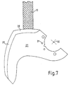
- Fig. 7 is a cutter knife 27 with two at an angle mutually standing cutting zones 28 are shown.
- the Sanding belt 10 just touches the cutting zone 28, which as First to be sanded. With such a The different cutting zones 28, 29 become knife-shaped sanded one after the other. This means that everyone first Infeeds 19 to 26 in the area of the cutting zone 28 be approached one after the other and then the Cutting zone 29 is processed accordingly.
Landscapes
- Engineering & Computer Science (AREA)
- Mechanical Engineering (AREA)
- Finish Polishing, Edge Sharpening, And Grinding By Specific Grinding Devices (AREA)
Applications Claiming Priority (2)
| Application Number | Priority Date | Filing Date | Title |
|---|---|---|---|
| DE10017719A DE10017719A1 (de) | 2000-04-11 | 2000-04-11 | Vorrichtung zum Schleifen von Messern |
| DE10017719 | 2000-04-11 |
Publications (1)
| Publication Number | Publication Date |
|---|---|
| EP1145800A1 true EP1145800A1 (fr) | 2001-10-17 |
Family
ID=7638192
Family Applications (1)
| Application Number | Title | Priority Date | Filing Date |
|---|---|---|---|
| EP01108883A Withdrawn EP1145800A1 (fr) | 2000-04-11 | 2001-04-10 | Dispositif d'affûtage de couteaux |
Country Status (3)
| Country | Link |
|---|---|
| US (1) | US6638142B2 (fr) |
| EP (1) | EP1145800A1 (fr) |
| DE (1) | DE10017719A1 (fr) |
Cited By (3)
| Publication number | Priority date | Publication date | Assignee | Title |
|---|---|---|---|---|
| EP1537772A1 (fr) * | 2003-12-06 | 2005-06-08 | Deere & Company | Dispositif d'affûtage |
| BE1029073B1 (de) * | 2021-02-22 | 2022-10-27 | Deere & Co | Schleifeinrichtung für eine mit einer Anzahl an Messern versehene Häckseltrommel eines Feldhäckslers |
| DE102005013363B4 (de) | 2004-05-13 | 2023-01-05 | Weber Maschinenbau Gmbh Breidenbach | Maschine zum Schärfen von Rotationsmessern |
Families Citing this family (7)
| Publication number | Priority date | Publication date | Assignee | Title |
|---|---|---|---|---|
| ES2282720T3 (es) * | 2003-01-02 | 2007-10-16 | Cinetic Landis Grinding Limited | Control de muela de rectificar. |
| CN100443259C (zh) * | 2006-08-03 | 2008-12-17 | 上海交通大学 | 数控鞋楦刀具磨刀机精确步进机构 |
| ITFI20130292A1 (it) * | 2013-11-30 | 2015-05-31 | Futura Spa | Dispositivo per il controllo dell'affilatura di lame a nastro. |
| CN104819797B (zh) * | 2015-04-27 | 2017-09-29 | 东莞市恒宇仪器有限公司 | 削笔机切削扭力试验机 |
| EP3366439A1 (fr) * | 2017-02-27 | 2018-08-29 | Bizerba SE & Co. KG | Machine pour la découpe des aliments avec dispositif pour la supervision de la condition du couteau |
| IT202000016024A1 (it) * | 2020-07-02 | 2022-01-02 | Paper Converting Machine Company S P A | Metodo di controllo del processo di affilatura di una lama di taglio in una macchina troncatrice |
| DE102022112000A1 (de) | 2022-05-12 | 2023-11-16 | Dipl.Ing. S c h i n d l e r & Wagner GmbH & Co KG | Vorrichtung zum Schäfen und Verfahren zum Betrieb der Vorrichtung |
Citations (5)
| Publication number | Priority date | Publication date | Assignee | Title |
|---|---|---|---|---|
| US4418499A (en) * | 1979-11-01 | 1983-12-06 | Shinko Machinery Works Inc. | Cutter grinding machine |
| DE3732058A1 (de) * | 1987-09-23 | 1989-04-06 | Fortuna Werke Maschf Ag | Schleifeinrichtung fuer ein glockenmesser einer schaerfmaschine |
| JPH07266197A (ja) * | 1994-03-28 | 1995-10-17 | Saisu:Kk | センサ付装置、センサ付研削装置及びセンサ |
| DE9117307U1 (de) * | 1991-08-02 | 1999-10-28 | E. Siepmann & Co (GmbH & Co), 42655 Solingen | Topfschleifmaschine, insbesondere zum Schleifen von Scherenteilen |
| DE19836804A1 (de) * | 1998-08-14 | 2000-02-17 | Knecht Gmbh Maschbau | Vorrichtung zum Schleifen der Schneiden von Schleifwerkzeugen |
Family Cites Families (5)
| Publication number | Priority date | Publication date | Assignee | Title |
|---|---|---|---|---|
| IT1156629B (it) * | 1982-07-14 | 1987-02-04 | Gd Spa | Dispositivo di affilatura per lame rotanti |
| US4843767A (en) * | 1988-03-28 | 1989-07-04 | Deere & Company | Automatic forage harvester knife sharpening system |
| US5067378A (en) * | 1989-06-23 | 1991-11-26 | Gerber Garment Technology, Inc. | Blade for cutting sheet material and related cutting method |
| US5098027A (en) * | 1990-02-28 | 1992-03-24 | Ford New Holland, Inc. | Automatic knife sharpening system for forage harvesters |
| DE19629668C1 (de) * | 1996-07-23 | 1998-01-02 | Pallmann Kg Maschf | Verfahren und Vorrichtung zum Nachschärfen von Messern für Zerkleinerungsmaschinen, insbesondere von Zerspanmessern für Holz |
-
2000
- 2000-04-11 DE DE10017719A patent/DE10017719A1/de not_active Withdrawn
-
2001
- 2001-04-10 EP EP01108883A patent/EP1145800A1/fr not_active Withdrawn
- 2001-04-11 US US09/829,984 patent/US6638142B2/en not_active Expired - Lifetime
Patent Citations (5)
| Publication number | Priority date | Publication date | Assignee | Title |
|---|---|---|---|---|
| US4418499A (en) * | 1979-11-01 | 1983-12-06 | Shinko Machinery Works Inc. | Cutter grinding machine |
| DE3732058A1 (de) * | 1987-09-23 | 1989-04-06 | Fortuna Werke Maschf Ag | Schleifeinrichtung fuer ein glockenmesser einer schaerfmaschine |
| DE9117307U1 (de) * | 1991-08-02 | 1999-10-28 | E. Siepmann & Co (GmbH & Co), 42655 Solingen | Topfschleifmaschine, insbesondere zum Schleifen von Scherenteilen |
| JPH07266197A (ja) * | 1994-03-28 | 1995-10-17 | Saisu:Kk | センサ付装置、センサ付研削装置及びセンサ |
| DE19836804A1 (de) * | 1998-08-14 | 2000-02-17 | Knecht Gmbh Maschbau | Vorrichtung zum Schleifen der Schneiden von Schleifwerkzeugen |
Non-Patent Citations (1)
| Title |
|---|
| PATENT ABSTRACTS OF JAPAN vol. 1996, no. 02 29 February 1996 (1996-02-29) * |
Cited By (3)
| Publication number | Priority date | Publication date | Assignee | Title |
|---|---|---|---|---|
| EP1537772A1 (fr) * | 2003-12-06 | 2005-06-08 | Deere & Company | Dispositif d'affûtage |
| DE102005013363B4 (de) | 2004-05-13 | 2023-01-05 | Weber Maschinenbau Gmbh Breidenbach | Maschine zum Schärfen von Rotationsmessern |
| BE1029073B1 (de) * | 2021-02-22 | 2022-10-27 | Deere & Co | Schleifeinrichtung für eine mit einer Anzahl an Messern versehene Häckseltrommel eines Feldhäckslers |
Also Published As
| Publication number | Publication date |
|---|---|
| DE10017719A1 (de) | 2001-10-18 |
| US20010029148A1 (en) | 2001-10-11 |
| US6638142B2 (en) | 2003-10-28 |
Similar Documents
| Publication | Publication Date | Title |
|---|---|---|
| EP2837456B1 (fr) | Scie mécanique et procédé de commande d'une scie mécanique | |
| EP2573001B1 (fr) | Dispositif et méthode d'application d'un chemin de coupe sur un suremballage | |
| EP3027359B1 (fr) | Arrangement comprenant une machine-outil à guidage manuel et un disque de dégrossissage | |
| EP1409210B1 (fr) | Procede pour le reglage de l'epaisseur de coupe | |
| EP1145800A1 (fr) | Dispositif d'affûtage de couteaux | |
| DE4023114A1 (de) | Verfahren zum feststellen der schaerfe von haeckselmessern | |
| EP3600713B1 (fr) | Dispositif, en particulier machine, pour la fabrication de fil de wiegand à partir d'un fil, en particulier d'un fil d'impulsion, et procédé pour le fonctionnement d'un dispositif | |
| DE19753563B4 (de) | Schneidvorrichtung für Flachmaterialbahnen | |
| DE19756503B4 (de) | Kehlmaschine | |
| DE202019100128U1 (de) | Holzbearbeitungsmaschine und Steuerungsvorrichtung für eine Holzbearbeitungsmaschine | |
| DD286735A5 (de) | Verfahren zum feststellen der schaerfe von haeckselmessern | |
| DE3741973C2 (fr) | ||
| EP2796242B1 (fr) | Machine d'ébavurage et son procédé de réglage | |
| DE102020105223B4 (de) | Vorrichtung zur Vorhersage eines Blattabrisses eines Bandsägeblattes einer Bandsäge | |
| DE3930306C2 (fr) | ||
| CH697240B1 (de) | Vorrichtung zur Bearbeitung von Glasplatten. | |
| EP4122313B1 (fr) | Procédé de détermination de l'état d'usure d'une contre-lame agencée sur un porte-contre-lame, ainsi que ramasseuse-hacheuse autonome | |
| DE20006415U1 (de) | Vorrichtung zum Schleifen von Messern | |
| EP1800815B1 (fr) | Machine pour travailler le bois et procédé pour déterminer une valeur de correction pour machines à travailler le bois | |
| DE4130799A1 (de) | Laengsschneidemaschine mit elektrischem stellantrieb fuer die messeranordnung | |
| EP0495354A1 (fr) | Aménagement pour traiter des pièces à usiner de tissu, en particulier en cuir ou similaires | |
| DE102021111672A1 (de) | Vorrichtung zum Bearbeiten von flächigen Werkstücken | |
| DE8916001U1 (de) | Vorrichtung zur materialabhebenden Fein- oder Feinstbearbeitung | |
| DE20005348U1 (de) | Kreissägemaschine | |
| EP0707079A1 (fr) | Dispositif pour parer les bords de pièces de cuir |
Legal Events
| Date | Code | Title | Description |
|---|---|---|---|
| PUAI | Public reference made under article 153(3) epc to a published international application that has entered the european phase |
Free format text: ORIGINAL CODE: 0009012 |
|
| AK | Designated contracting states |
Kind code of ref document: A1 Designated state(s): AT BE CH CY DE DK ES FI FR GB GR IE IT LI LU MC NL PT SE TR |
|
| AX | Request for extension of the european patent |
Free format text: AL;LT;LV;MK;RO;SI |
|
| 17P | Request for examination filed |
Effective date: 20020409 |
|
| AKX | Designation fees paid |
Free format text: AT BE CH CY DE DK ES FI FR GB GR IE IT LI LU MC NL PT SE TR |
|
| 17Q | First examination report despatched |
Effective date: 20061019 |
|
| 17Q | First examination report despatched |
Effective date: 20061019 |
|
| STAA | Information on the status of an ep patent application or granted ep patent |
Free format text: STATUS: THE APPLICATION IS DEEMED TO BE WITHDRAWN |
|
| 18D | Application deemed to be withdrawn |
Effective date: 20070801 |