EP1145814A2 - Fliesenschneidvorrichtung - Google Patents
Fliesenschneidvorrichtung Download PDFInfo
- Publication number
- EP1145814A2 EP1145814A2 EP00111903A EP00111903A EP1145814A2 EP 1145814 A2 EP1145814 A2 EP 1145814A2 EP 00111903 A EP00111903 A EP 00111903A EP 00111903 A EP00111903 A EP 00111903A EP 1145814 A2 EP1145814 A2 EP 1145814A2
- Authority
- EP
- European Patent Office
- Prior art keywords
- tile
- supporting
- supporting rail
- rail
- post
- Prior art date
- Legal status (The legal status is an assumption and is not a legal conclusion. Google has not performed a legal analysis and makes no representation as to the accuracy of the status listed.)
- Withdrawn
Links
Images


Classifications
-
- B—PERFORMING OPERATIONS; TRANSPORTING
- B26—HAND CUTTING TOOLS; CUTTING; SEVERING
- B26D—CUTTING; DETAILS COMMON TO MACHINES FOR PERFORATING, PUNCHING, CUTTING-OUT, STAMPING-OUT OR SEVERING
- B26D1/00—Cutting through work characterised by the nature or movement of the cutting member or particular materials not otherwise provided for; Apparatus or machines therefor; Cutting members therefor
- B26D1/01—Cutting through work characterised by the nature or movement of the cutting member or particular materials not otherwise provided for; Apparatus or machines therefor; Cutting members therefor involving a cutting member which does not travel with the work
- B26D1/04—Cutting through work characterised by the nature or movement of the cutting member or particular materials not otherwise provided for; Apparatus or machines therefor; Cutting members therefor involving a cutting member which does not travel with the work having a linearly-movable cutting member
-
- B—PERFORMING OPERATIONS; TRANSPORTING
- B28—WORKING CEMENT, CLAY, OR STONE
- B28D—WORKING STONE OR STONE-LIKE MATERIALS
- B28D1/00—Working stone or stone-like materials, e.g. brick, concrete or glass, not provided for elsewhere; Machines, devices, tools therefor
- B28D1/22—Working stone or stone-like materials, e.g. brick, concrete or glass, not provided for elsewhere; Machines, devices, tools therefor by cutting, e.g. incising
- B28D1/225—Working stone or stone-like materials, e.g. brick, concrete or glass, not provided for elsewhere; Machines, devices, tools therefor by cutting, e.g. incising for scoring or breaking, e.g. tiles
-
- Y—GENERAL TAGGING OF NEW TECHNOLOGICAL DEVELOPMENTS; GENERAL TAGGING OF CROSS-SECTIONAL TECHNOLOGIES SPANNING OVER SEVERAL SECTIONS OF THE IPC; TECHNICAL SUBJECTS COVERED BY FORMER USPC CROSS-REFERENCE ART COLLECTIONS [XRACs] AND DIGESTS
- Y10—TECHNICAL SUBJECTS COVERED BY FORMER USPC
- Y10T—TECHNICAL SUBJECTS COVERED BY FORMER US CLASSIFICATION
- Y10T225/00—Severing by tearing or breaking
- Y10T225/30—Breaking or tearing apparatus
- Y10T225/307—Combined with preliminary weakener or with nonbreaking cutter
- Y10T225/321—Preliminary weakener
- Y10T225/325—With means to apply moment of force to weakened work
-
- Y—GENERAL TAGGING OF NEW TECHNOLOGICAL DEVELOPMENTS; GENERAL TAGGING OF CROSS-SECTIONAL TECHNOLOGIES SPANNING OVER SEVERAL SECTIONS OF THE IPC; TECHNICAL SUBJECTS COVERED BY FORMER USPC CROSS-REFERENCE ART COLLECTIONS [XRACs] AND DIGESTS
- Y10—TECHNICAL SUBJECTS COVERED BY FORMER USPC
- Y10T—TECHNICAL SUBJECTS COVERED BY FORMER US CLASSIFICATION
- Y10T83/00—Cutting
- Y10T83/02—Other than completely through work thickness
- Y10T83/0333—Scoring
- Y10T83/0385—Rotary scoring blade
Definitions
- This invention relates to a tile cutter.
- a conventional tile cutter for example, as disclosed by Japanese utility model publication No. 52-35592 and No. 55-56008, has a construction in which fixation posts facing each other are formed uniformly with a base of large install area or attached and fixed to the base, a supporting rail is arranged on a line connecting the above fixation posts approximately on a central portion of the base, a tile placing face covered with a tile supporting elastic plate of which thickness is approximately same as height of the supporting rail is formed on the both sides of the supporting rail, a scale for measuring tile cutting dimension is arranged on the base around the tile placing face, a guide rail parallel to and just above the supporting rail is placed on the fixation posts facing each other, and a tile cutting operation unit provided with a cutter and a tile pressing leg protruding to both sides on a lower end portion of an operation lever is supported by the guide rail as to freely slide.
- the tile placing face covered with a tile supporting elastic plate is formed on the both sides of the supporting rail, when the tile pressing leg presses both sides of a cutting line which is drawn by the tile cutting operation unit, the pressing force is dispersed by resistance of the tile supporting elastic plate on the tile placing face and hardly concentrates on the cutting line. Therefore, accurate cutting on the cutting line and making a fine cutting face require skill. Especially, in cutting a thick tile, required degree of skill is high, cracks and chips tend to be generated at both ends of the cutting line etc., defective products are frequently generated thereby.
- the tile cutter becomes of large width, weight, and volume for the base supporting the tile supporting elastic plate. Cost of making the tile cutter itself increases thereby. Cost is also increased by complicated packing, large amount of packing materials, and transportation of the tile cutter. Further, uneconomical storage and inconvenience of handling are caused on users' side.
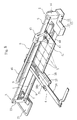
- Figure 1 shows a preferred embodiment of a tile cutter of the present invention
- Figure 2 is a cross-sectional view at A-A line shown in Figure 1
- Figure 3 is a cross-sectional view at B-B line shown in Figure 1.
- 1 is a supporting rail of which cross section is an inverted T
- a front fixation post 2 is attached to an end of the supporting rail 1
- a rear fixation post 3 is attached to the other end of the supporting rail 1.
- 4 is a detachable scale for measuring cutting dimension of a tile, which is arranged on the supporting rail 1 as to freely slide.
- a guide rail 5 is arranged on upper ends of the front fixation post 2 and rear fixation post 3 and parallel to the supporting rail 1, and a tile cutting operation unit 6 is arranged on the guide rail 5 as to freely slide.
- a longitudinal direction parallel to the supporting rail 1 is defined as a back-and-forth direction, and a direction at right angles with the supporting rail 1 is defined as a left-and-right direction.
- the supporting rail 1 having a straight supporting ridge portion 7 in longitudinal direction and left and right side portions 8 on a lower end of the supporting ridge portion 7, is formed into an inverted T in cross section with band plate steel as to have a rounded top portion 9 of the supporting ridge portion 7 and rounded end portions 10 of the side portions 8. That is to say, the rounded top portion 9 is formed by bending a sheet of band plate steel for 180 ° at a central portion of the steel, the supporting ridge portion 7 is formed by bending the band plate steel for 90° , and the rounded end portions 10 are formed by bending the band plate steel for 180° at side ends. In this case, the side ends of the band plate steel are placed to angles formed with the supporting ridge portion 7 and the side portions 8.
- the top portion 9 of the supporting ridge portion 7 and the end portions 10 of the side portions 8 are rounded by forming the supporting rail 1 as described above, and safety for prevention of injury such as cutting hands of operators is enhanced.
- the guide rail 5 is formed with steel as to have a rectangular cross section.
- the front fixation post 2 is composed of a base portion 13 of T-shaped in a top view having a tile contact portion 11 at right angles with the supporting rail 1 and a fixation portion 12 protruding forward from a middle portion of the tile contact portion 11, and a post portion 14 standing on an upper face of the fixation portion 12 of the base portion 13.
- the front fixation post 2 is uniformly die-cast with aluminum as a whole.
- the tile contact portion 11 of the base portion 13 has a rectangular-box shape with a downward opening, a notched concave portion 17 is formed on a rear face 16 side of an upper face 15 middle of the tile contact portion 11, a staged portion 18 is formed on the rear face 16 side of the bottom face of the notched concave portion 17, and an approximately V-shaped notch 19 for tile positioning having a right angle is notched on a middle part on the rear face 16 side of the staged portion 18 in vertical direction leaving a stepped portion 19a (refer to Figure 6).
- the fixation portion 12 of the base portion 13 also has a rectangular-box shape with a downward opening, and a concave groove 20 opening downward for insertion of the supporting ridge portion 7 of the supporting rail 1 is formed in a middle part of the fixation portion 12 in a longitudinal direction. Further, a shallow concave portion 21 opening downward for fitting the both side portions 8 of the supporting rail 1 is formed on a lower part of the fixation portion 12, and a notched groove 22 opening backward is formed on an upper end of the post portion 14.
- a front end of the guide rail 5 is inserted to the notched portion 22 of the post portion 14, a bolt 23 is inserted to holes disposed on the post portion 14 and the guide rail 5 and fastened with a nut 24, and the guide rail 5 is held by left and right wall portions of the notched groove 22.
- a front end of the supporting rail 1 is inserted to the concave groove 20 and the concave portion 21 of the fixation portion 12, another bolt 23 is inserted to holes disposed on the fixation portion 12 and the supporting rail 1 and fastened with another nut 24, and the supporting ridge portion 7 of the supporting rail 1 is held by left and right wall portions of the concave groove 20.
- the rear fixation post 3 is formed into an inverted T-shape having a post portion 25 having U-shaped cross-sectional configuration for holding a rear end of the guide rail 5 and a rear end of the supporting ridge portion 7, a pair of holding piece portions 26 for holding the side portions 8 of the supporting rail 1 formed on a lower end of the post portion 25, and a flat board portion 27 disposed on a lower face side of the holding piece portions 26.
- the post portion 25 and the pair of holding piece portions 26 are formed with a bent sheet of steel plate, and a slit 28 in vertical direction opening forward is formed in the post portion 25. And, the pair of holding piece portions 26 is bent and formed as to form a concave portion for fitting the side portions 8 of the supporting rail 1.
- the side portions 8 of the supporting rail 1 are respectively fixed to an upper face of the flat board portion 27 of the rear fixation post 3 by spot welding. 29 is a welded portion of the spot welding, layered portions of the metal plate forming the side portions 8 are also welded.
- the holding piece portions 26 are placed on the side portions 8 of the supporting rail 1, the supporting ridge portion 7 is inserted to the slit 28 of the post portion 25, and the left and right holding piece portions 26 are respectively fixed to the upper face of the flat board portion 27 by spot welding.
- the bolt 23 is inserted to the holes formed on the post portion 25 and the supporting rail 1 and fastened with the nut 24.
- the rear end of the guide rail 5 is inserted to the slit 28 of the post portion 25 of the rear fixation post 3, and the bolt 23 is inserted to the holes formed on the post portion 25 and the guide rail 1 and fastened with the nut 24.
- the rectangular flat board portion 27 of the rear fixation post 3 is formed into a size serving as a footboard, and four angles of the flat board portion 27 are rounded.
- the flat board portion 27 is covered with an elastic cover 30 having a holding piece 30a which is U-shaped in a top view along the periphery of the upper face of the flat board portion 27.
- the elastic cover 30, composed of rubber, foamed plastic, etc., is a safety cover to prevent injury in case that an operator falls the tile cutter in handling, and the flat board portion 27 hits the foot of the operator.
- placement stage portions 25a are formed on the front end of the post portion 25 of the rear fixation post 3 (a front end face of the metal plate bent to be U-shaped).
- the placement stage portions 25a, formed by notching the front end of the upper portion of the post portion 25, is for placing a tile pressing leg (described later) of the tile cutting operation unit 6.
- the scale 4 is provided with a scale main body 31 (made of aluminum, for example) detachably attached to the supporting rail 1 in a direction at right angles with the supporting rail 1 (the left-and-right direction) and an L-shaped sliding scale 34 attached along one pair of guide grooves 33 formed in the left-and-right direction on an upper face 32 of the scale main body 31 as to freely slide.
- a scale main body 31 made of aluminum, for example
- the scale main body 31 has a graduation 35 graduated in inches between the pair of guide grooves 33, and a graduation 36 graduated in centimeters in front of the graduation 35 in inches. And, a tile receiving plate 38 in the left-and-right direction is arranged on a lower position than the upper face 32 in front of the graduation 36 in centimeters through a stepped face portion 37.
- a V-groove 39 is formed in the back-and-forth direction on a base position (a position of 0 cm) on the graduation 36 in centimeters, and the (above-mentioned) notch 40 for tile positioning approximately V-shaped with a right angle is notched vertically on a position of the V-groove 39 of the above stepped face portion 37. That is to say, in a state in which the scale 4 is attached to the supporting rail 1, the notch 40 is disposed as to face the notch 19 of the front fixation post 2.
- a slit in the back-and-forth direction is formed on a position corresponding to the above V-groove 39 on the tile receiving plate 38, and a pair of sliding blocks 42 forming a concave groove 41 in the back-and-forth direction with the slit continuously on a lower face of the scale main body 31.
- the scale 4 is attached to the supporting rail 1 slidably and detachably by fitting the concave groove 41 to the supporting ridge portion 7 of the supporting rail 1.
- an upper face 38a of the tile receiving plate 38 corresponds to the top portion 9 of the supporting ridge portion 7 on the same plane, and the scale 4 is held horizontally by the sliding blocks 42 without trembling.
- width dimension of the concave groove 41 is approximately same as the thickness of the supporting ridge portion 7.
- lower faces of the sliding blocks 42 may contact upper faces of the side portions 8.
- the sliding scale 34 of the scale 4 is composed of a gate-shaped slide portion 43 having a window portion for reading the graduation 35 in inches on each of the left side and the right side and slidably fitted to the guide grooves 33 of the scale main body 31, and an arm portion 44 for tile-positioning and measuring attached to an end side of the slide portion 43 as to be at right angles with the slide portion 43.
- the sliding scale 34 is fixed to a desirable position with wing nuts and washers screwed on the scale main body 31.
- the tile cutting operation unit 6 has a sliding portion 45 having a through hole to which the supporting rail 1 is inserted, an operation lever 46 inserted and fixed to a cylinder portion 45a of an upper portion of the sliding portion 45, and a tile pressing leg 47 and a circular cutting blade 48 on a lower portion of the sliding portion 45.
- a lower face of the tile pressing leg 47 which inclines slightly downward to the both sides is covered with an elastic sheet piece 49 made of rubber, etc.
- the tile cutting operation unit 6 does not interfere with the scale 4 drawn to the rear end of the supporting rail 1 because the tile pressing leg 47 of the tile cutting operation unit 6 is placed on the placement stage portions 25a of the post portion 25 of the rear fixation post 3 as shown in Figure 4.
- the flat board portion 27 of the rear fixation post 3 is stamped by a foot 50 of an operator (refer to Figure 4) to fix the tile cutter, and the tile cutting operation unit 6 is moved forward from the rear side to the front side to form (press to cut) a cutting line on the surface (upper face) of the tile T with the circular cutting blade 48.
- edge of the circular cutting blade 48 is not damaged for clearance of the V-groove 39 on the scale 4 side and the notched concave portion 17 on the tile contact portion 11 side, and the cutting line is formed thoroughly for a space formed with the notch 40 on the scale 4 side and the tile T and a space formed with the notch 19 on the tile contact portion 11 side and the tile T.
- the elastic cover 30 prevents slippage.
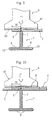
- the operation lever 46 is oscillated downward to press the both sides of the cutting line on the tile T with the pressing leg 47, rear edge of the tile T on the tile receiving piece 38 side slightly raises, reaction force from the supporting ridge portion 7 concentrates on the cutting line, and the tile T is cut (pressed to part) accurately on the cutting line. That is to say, the tile T is cut with fine cutting faces without cracks running out of the cutting line and chips because the tile T is pressed on three points, namely, the top portion 9 of the supporting ridge portion 7 corresponding to the cutting line, and two points, each of which is on the right side and the left side of the cutting line respectively, where the tile pressing leg 47 presses the tile T. In this case, as shown in Figure 9, accurate cut on the cutting line (fine cutting face) is realized even with a small width W.
- the tile T is pinched at its two corners facing each other by the notch 19 for tile positioning on the tile contact portion 11 side and the notch 40 for tile positioning on the scale 4 side.
- the tile T is held by the stepped portion 19a of the tile contact portion 11, the supporting rail 1, and the tile receiving plate 38 of the scale 4.
- a diagonal line, on which the tile T is cut corresponds to the top portion 9 of the supporting ridge portion 7.
- the flat board portion 27 of the rear fixation post 3 is stamped by a foot 50 of an operator (refer to Figure 4), the tile T is lightly held by a hand to be stable, the tile cutting operation unit 6 is pushed from the rear side to the front side as a cutting line is formed on the diagonal line on the surface (upper face) of the tile T with the circular cutting blade 48. Then, as described with reference to Figure 9, the tile pressing leg 47 presses the tile T on the both sides of the cutting line, and the tile T is cut into triangles of fine cutting faces without generating cracks and chips running out of the cutting line.
- a "mosaic tile” composed of plural pieces of tile T, of which reverse sides are stuck to paper or net, or of which sides are connected by applying soft synthetic rubber or plastic, can be cut with the tile cutter of the present invention.
- a rectangle receiving board G composed of hard rubber, hard plastic, etc. is placed on the upper face 38a of the tile receiving plate 38 of the scale 4 and the top portion 9 of the supporting ridge portion 7 of the supporting rail 1, and the mosaic tile is placed on the receiving board G.
- cutting lines are formed on the plural pieces of tile T by the tile cutting operation unit 6, and each piece of the tile T is cut into a predetermined width W by pressing both sides of the cutting line with the tile pressing leg 47 as shown in Figure 10.
- the receiving board G is slightly bent on the both sides of the top portion 9 of the supporting ridge portion 7 of the supporting rail 1 elastically by pressing force of the tile pressing leg 47, reaction force from the supporting ridge portion 7 concentrates on the cutting line, and even the tile T of small width W can be cut with fine cutting face without cracks and chips on the cutting line thereby.
- the mosaic tile not restricted to a cluster of the square tiles T, can be a cluster of rectangular tiles T, circular tiles T, or tiles T of plural different configurations to be cut.
- the tile cutter of the present invention when a cutting line is formed on the tile T by the tile cutting operation unit 6 and pressing force is loaded on the both sides of the cutting line by the tile pressing leg 47, the pressing force (not resisted and dispersed by a tile supporting elastic plate as in conventional tile cutters) concentrates on the cutting line, and accurate cut on the cutting line and fine cutting faces are obtained irrespective of the thickness of the tile, without skill, and even with the small width W. That is to say, problems of cracks and chips conventionally generated on end portions of the cutting line are resolved, and defective products are prevented thereby.
- the tile cutter can be simplified with sufficient strength, and production cost can be greatly reduced by reducing the number of parts and cost of dies for die cast with aluminum (in comparison with a conventional tile cutter). And, the tile cutter is easy to carry and handle for its light weight, and operationality is improved thereby. Further, safety, which prevents injury such as cutting hands in handling of the tile cutter, is enhanced by rounding the top portion 9 of the supporting ridge portion 7 and the end portions 10 of the side portions 8.
- the tile cutting operation unit 6 does not interfere with the scale 4 drawn to the rear end of the supporting rail 1 because the tile pressing leg 47 of the tile cutting operation unit 6 is placed on the placement stage portions 25a of the post portion 25 of the rear fixation post 3.
- the tile cutter can be fixed by stamping the flat board portion 27 of the rear fixation post 3 with a foot of an operator, and tile cutting work is conducted without instability. And, for example, in case that the operator falls the tile cutter by mistake in handling and the flat board portion 27 hits the foot of the operator, the foot is not injured for the elastic cover 30 covering the flat board portion 27. And, the elastic cover 30 prevents slippage when the flat board portion 27 is stamped in tile cutting.
Landscapes
- Engineering & Computer Science (AREA)
- Mechanical Engineering (AREA)
- Mining & Mineral Resources (AREA)
- Life Sciences & Earth Sciences (AREA)
- Forests & Forestry (AREA)
- Processing Of Stones Or Stones Resemblance Materials (AREA)
- Finishing Walls (AREA)
Applications Claiming Priority (2)
| Application Number | Priority Date | Filing Date | Title |
|---|---|---|---|
| JP2000106762A JP3504578B2 (ja) | 2000-04-07 | 2000-04-07 | タイルカッター |
| JP2000106762 | 2000-04-07 |
Publications (2)
| Publication Number | Publication Date |
|---|---|
| EP1145814A2 true EP1145814A2 (de) | 2001-10-17 |
| EP1145814A3 EP1145814A3 (de) | 2002-04-03 |
Family
ID=18619879
Family Applications (1)
| Application Number | Title | Priority Date | Filing Date |
|---|---|---|---|
| EP20000111903 Withdrawn EP1145814A3 (de) | 2000-04-07 | 2000-06-13 | Fliesenschneidvorrichtung |
Country Status (5)
| Country | Link |
|---|---|
| US (1) | US6223736B1 (de) |
| EP (1) | EP1145814A3 (de) |
| JP (1) | JP3504578B2 (de) |
| KR (1) | KR20010090692A (de) |
| CN (1) | CN1317403A (de) |
Cited By (1)
| Publication number | Priority date | Publication date | Assignee | Title |
|---|---|---|---|---|
| DE202017001237U1 (de) | 2017-03-09 | 2018-03-12 | Rauch Landmaschinenfabrik Gmbh | Verteilmaschine und hierfür geeignetes Dosierorgan |
Families Citing this family (23)
| Publication number | Priority date | Publication date | Assignee | Title |
|---|---|---|---|---|
| CA98754S (en) | 2001-09-13 | 2003-03-25 | Turner Intellect Property Ltd | Tile cutter |
| US6672496B2 (en) * | 2002-04-08 | 2004-01-06 | Eastman Kodak Company | Derelict product cracker, nest, and cracking method |
| USD541127S1 (en) * | 2005-10-27 | 2007-04-24 | Te-Chuan Yang | Tile cutter |
| US10556183B2 (en) | 2006-01-10 | 2020-02-11 | Winview, Inc. | Method of and system for conducting multiple contest of skill with a single performance |
| ES1062584Y (es) * | 2006-03-27 | 2006-10-01 | Boada Germans Sa | Cortadora manual de ceramica |
| KR100718971B1 (ko) * | 2006-08-08 | 2007-05-16 | 홍순철 | 타일 절단기 |
| US7748372B2 (en) * | 2007-12-11 | 2010-07-06 | Marshalltown Company | Adaptable tile-cutter apparatus for receiving disparately-sized tiles |
| KR101055302B1 (ko) | 2008-04-17 | 2011-08-09 | 오영규 | 석판 가공장치 |
| KR101048166B1 (ko) * | 2009-04-20 | 2011-07-08 | 전병국 | 타일 절단기 |
| CN103286800B (zh) * | 2012-02-28 | 2015-06-24 | 上海英祺精密零件制造有限公司 | 一种切除胶带装置 |
| ES2502040B1 (es) * | 2013-03-01 | 2015-07-07 | Bellota Herramientas, S.A. | Sistema de rotura monopunto ambidiestro para máquinas cortadoras de cerámica. |
| USD742944S1 (en) * | 2013-03-15 | 2015-11-10 | Bellota Herramientas, S.A. | Handle of cutting wheels for ceramic cutting machines |
| CN103507163A (zh) * | 2013-09-12 | 2014-01-15 | 陆光华 | 一种石材切割机 |
| USD737109S1 (en) * | 2013-09-19 | 2015-08-25 | Germans Boada, S.A. | Cutter |
| USD756186S1 (en) * | 2014-09-05 | 2016-05-17 | Germans Boada, S.A. | Ceramic cutters |
| US20160101536A1 (en) * | 2014-10-10 | 2016-04-14 | Gregory J. Gundlach | Plank and tile cutter incorporating scale means |
| AU360488S (en) * | 2014-12-01 | 2015-02-27 | Germans Boada | Ceramic cutter |
| AU360530S (en) * | 2014-12-01 | 2015-03-03 | Germans Boada | Ceramic cutter |
| USD771457S1 (en) * | 2015-02-27 | 2016-11-15 | Cortag Industria E Comercio Ltda | Ceramic floor cutter |
| US10195767B2 (en) * | 2015-11-02 | 2019-02-05 | Artaic, Llc | Method and apparatus for cutting mosaic tile |
| CN105437382B (zh) * | 2015-11-05 | 2017-05-03 | 海门市瑞泰纺织科技有限公司 | 一种瓷砖拆卸装置的切割装置 |
| CN109693315B (zh) * | 2019-03-07 | 2020-03-17 | 杭州富阳飞尚装饰工程有限公司 | 一种装潢使用的室内瓷砖切割器 |
| USD1036955S1 (en) * | 2021-09-10 | 2024-07-30 | Cortag Industria E Comercio Ltda. | Tile cutter |
Family Cites Families (12)
| Publication number | Priority date | Publication date | Assignee | Title |
|---|---|---|---|---|
| US2205717A (en) * | 1939-09-11 | 1940-06-25 | Fleming A Fedon | Tile scoring and breaking device |
| JPS5235592A (en) | 1975-09-12 | 1977-03-18 | Seiko Instr & Electronics Ltd | Piezo-oscillator |
| FR2328554A1 (fr) * | 1975-10-24 | 1977-05-20 | Muller Alfred | Appareil de coupe pour carreaux en faience, gres et autres produits ceramiques |
| JPS5556008A (en) | 1978-10-23 | 1980-04-24 | Toshiba Tungaloy Co Ltd | Diamond powder as raw material and production thereof, sintered body and production thereof using said powder, and diamond growing method |
| IT1220363B (it) * | 1988-05-13 | 1990-06-15 | Gianni Tagliaferro | Apparecchiatura equipaggiata per il taglio mediante troncatura di parti compelementari di mattonelle,marmette,piastrelle e simili da pavimentazione e da rivestimento di pareti |
| GB2261188B (en) * | 1991-11-06 | 1994-10-19 | Liu Wun Hui | Manually-operated tile cutter |
| JP2973067B2 (ja) * | 1993-08-05 | 1999-11-08 | 産経物産株式会社 | タイルカッター |
| US5480081A (en) * | 1993-09-24 | 1996-01-02 | Diamant Boart, Inc. | Scoring and breaking device with a carrying case therefor |
| US5560274A (en) * | 1994-09-15 | 1996-10-01 | North American Tile Tool Company | Manual tile cutter |
| JP3243600B2 (ja) * | 1996-11-26 | 2002-01-07 | 産経物産株式会社 | タイルカッター |
| GB9719491D0 (en) * | 1997-09-13 | 1997-11-19 | Turner Intellect Property Ltd | Cutting/breaking apparatus |
| US6047871A (en) * | 1999-05-04 | 2000-04-11 | Chen; Lung-Chih | Brick cutting apparatus |
-
2000
- 2000-04-07 JP JP2000106762A patent/JP3504578B2/ja not_active Expired - Lifetime
- 2000-06-13 EP EP20000111903 patent/EP1145814A3/de not_active Withdrawn
- 2000-06-13 US US09/592,414 patent/US6223736B1/en not_active Expired - Fee Related
- 2000-06-16 KR KR1020000033731A patent/KR20010090692A/ko not_active Ceased
-
2001
- 2001-04-06 CN CN01116308A patent/CN1317403A/zh active Pending
Cited By (1)
| Publication number | Priority date | Publication date | Assignee | Title |
|---|---|---|---|---|
| DE202017001237U1 (de) | 2017-03-09 | 2018-03-12 | Rauch Landmaschinenfabrik Gmbh | Verteilmaschine und hierfür geeignetes Dosierorgan |
Also Published As
| Publication number | Publication date |
|---|---|
| JP3504578B2 (ja) | 2004-03-08 |
| CN1317403A (zh) | 2001-10-17 |
| JP2001287221A (ja) | 2001-10-16 |
| KR20010090692A (ko) | 2001-10-19 |
| US6223736B1 (en) | 2001-05-01 |
| EP1145814A3 (de) | 2002-04-03 |
Similar Documents
| Publication | Publication Date | Title |
|---|---|---|
| US6223736B1 (en) | Tile cutter | |
| US6240914B1 (en) | Tile cutter | |
| US5619896A (en) | Base of a sawing machine | |
| US4089112A (en) | Adjustable blade knife | |
| US5205045A (en) | Household tile cutting gauge | |
| US5542182A (en) | Cove mitering tool | |
| JP3243600B2 (ja) | タイルカッター | |
| US4516452A (en) | Paper cutter | |
| US4281570A (en) | Rotary blade power saw attachment | |
| AU8155301A (en) | Tile cutter | |
| US5107600A (en) | Parallel measuring guide device | |
| EP0985481B1 (de) | Dekupiersäge mit Zweifachpositionierunsführungsschuh | |
| US4881437A (en) | Angle guide device | |
| US20030024370A1 (en) | Workbench holder system | |
| US3179136A (en) | Hand tool adapter | |
| JP3077189U (ja) | タイルカッター | |
| JPH0645288Y2 (ja) | 刃板加工機 | |
| CN209936007U (zh) | 圆锯 | |
| CN219685539U (zh) | 一种卡持装置及工具腰带 | |
| CN215661138U (zh) | 一种建筑瓷砖加工用具有划线机构的切割装置 | |
| CN2413869Y (zh) | 多功能工作台 | |
| JP3007543U (ja) | 切断機の工作物の防弾跳取付具 | |
| JPH10225816A (ja) | アングル切断金型 | |
| JPH078169Y2 (ja) | タイル切断機における定規装置 | |
| JPH07316Y2 (ja) | 印 台 |
Legal Events
| Date | Code | Title | Description |
|---|---|---|---|
| PUAI | Public reference made under article 153(3) epc to a published international application that has entered the european phase |
Free format text: ORIGINAL CODE: 0009012 |
|
| AK | Designated contracting states |
Kind code of ref document: A2 Designated state(s): DE ES FR GB IT Kind code of ref document: A2 Designated state(s): AT BE CH CY DE DK ES FI FR GB GR IE IT LI LU MC NL PT SE |
|
| AX | Request for extension of the european patent |
Free format text: AL;LT;LV;MK;RO;SI |
|
| PUAL | Search report despatched |
Free format text: ORIGINAL CODE: 0009013 |
|
| AK | Designated contracting states |
Kind code of ref document: A3 Designated state(s): AT BE CH CY DE DK ES FI FR GB GR IE IT LI LU MC NL PT SE |
|
| AX | Request for extension of the european patent |
Free format text: AL;LT;LV;MK;RO;SI |
|
| 17P | Request for examination filed |
Effective date: 20020904 |
|
| AKX | Designation fees paid |
Free format text: DE ES FR GB IT |
|
| STAA | Information on the status of an ep patent application or granted ep patent |
Free format text: STATUS: THE APPLICATION HAS BEEN WITHDRAWN |
|
| 18W | Application withdrawn |
Effective date: 20030317 |